Navigation

    • Register
    • Login
    • OpenHardware.io
    • Categories
    • Recent
    • Tags
    • Popular
    1. Home
    2. Matt
    3. Best
    • Profile
    • Following
    • Followers
    • Topics
    • Posts
    • Best
    • Groups

    Best posts made by Matt

    • 433mhz transmitter

      Its kinda kludgy (of course- I made it!) but it works. As usual full of bits pinched from elsewhere....
      I am using this to control 4 effergy wall outlets. I already have mains switching ability but it's made by me and I am nervous about fire, so I figured this was a good compromise.
      I have some cheap 433 transmitters and receivers. Used the RCSwitch library to capture the codes. I have only got one switch functional at the moment but to add the rest is trivial. My coding Im sure is crap but it works.
      I have soldered a wee wire to the transmitter 12CM long and have no issues with range. I like the 'repeat command x times' function in the RCSwitch library, kinda makes not having feedback a non issue.

      // Enable debug prints to serial monitor
      //#define MY_DEBUG 
      
      // Enable and select radio type attached
      #define MY_RADIO_NRF24
      //#define MY_RADIO_RFM69
      
      // Enable repeater functionality for this node
      // #define MY_REPEATER_FEATURE
      
      #include <SPI.h>
      #include <MySensors.h>
      #include <RCSwitch.h>
      
      #define NUMBER_OF_PLUGS 4 // Total number of attached plugs
      
      #define CODE_1On 1290271
      #define CODE_1Off 1290263
      #define CODE_2On 1290267
      #define CODE_2Off 1290259
      #define CODE_3On 1290269
      #define CODE_3Off 1290261
      #define CODE_4On 1290270
      #define CODE_4Off 1290262
      
      RCSwitch mySwitch = RCSwitch();
      
      void setup() {
        mySwitch.enableTransmit(4);
        mySwitch.setRepeatTransmit(15);
      }
      
      void presentation()  
      {   
        // Send the sketch version information to the gateway and Controller
        sendSketchInfo("433mhz switch", "1.0");
      
        for (int sensor=1 ; sensor<=NUMBER_OF_PLUGS;sensor++) {
          // Register all sensors to gw (they will be created as child devices)
          present(sensor, S_LIGHT);
        }
      }
      
      
      void loop() 
      {
        
      }
      
      void receive(const MyMessage &message) {
        // We only expect one type of message from controller. But we better check anyway.
        if (message.type==V_LIGHT) {
        int incomingLightState =  message.getBool(); 
        int incomingOutlet = message.sensor;
        
        Serial.print("Outlet #: ");
        Serial.println(message.sensor);
        Serial.print("Command: ");
        Serial.println(message.getBool());
       
       if (incomingOutlet==1) {
       if (incomingLightState==1) {
          // Turn on  socket 1
          Serial.println("Turn on Socket 1");
       mySwitch.send(CODE_1On, 24); // These codes are unique to each outlet
       delay(50); 
       }
       if (incomingLightState==0)  {
          // Turn off socket 1
       Serial.println("Turn off Socket 1");
      mySwitch.send(CODE_1Off, 24);
      delay(50); 
       }
       }
       if (incomingOutlet==2) {
       if (incomingLightState==1) {
          // Turn on  socket 2
          Serial.println("Turn on Socket 2");
      mySwitch.send(CODE_2On, 24);
       delay(50); 
       }
       if (incomingLightState==0)  {
          // Turn off socket 2
       Serial.println("Turn off Socket 2");
      mySwitch.send(CODE_2Off, 24);
      delay(50); 
       }
       }
       if (incomingOutlet==3) {
       if (incomingLightState==1) {
          // Turn on  socket 3
          Serial.println("Turn on Socket 3");
      mySwitch.send(CODE_3On, 24);
       delay(50); 
       }
       if (incomingLightState==0)  {
          // Turn off socket 3
       Serial.println("Turn off Socket 3");
      mySwitch.send(CODE_3Off, 24);
      delay(50); 
       }
       }
       if (incomingOutlet==4) {
       if (incomingLightState==1) {
          // Turn on  socket 4
          Serial.println("Turn on Socket 4");
       mySwitch.send(CODE_4On, 24);
       delay(50); 
       }
       if (incomingLightState==0)  {
          // Turn off socket 4
       Serial.println("Turn off Socket 4");
      mySwitch.send(CODE_4Off, 24);
      delay(50); 
       }
       }
        }
       delay(50);
      }
      
      
      posted in My Project
      Matt
      Matt
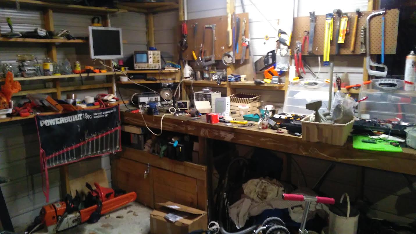
    • RE: Your workshop :)

      OK here's mine.
      0_1462611008576_WS.jpg

      posted in General Discussion
      Matt
      Matt
    • RE: LM393 as pulse powermeter sensor, swap out 'photodiode'

      OK so rather than wait for shipping from China I went to my local Jaycar and got one of these LDRs. If the link gets broken its a cadmium sulphine LDR with a rise time of 50ms and decay of 40ms.
      Works like a charm. Because its flat I can tape it directly to the LED in my power meter, covering the whole thing with black tape to ensure no ambient light problems. Two pinholes in the tape and the LDR leads go right through no probs. I have some thin wires going to the LM393 unit (so minimal weight on the LDR/Tape itself) and I guess the comparator in there is good enough to pick up the change in resistance on the LED pulses.
      So if you wind up with one of these units I recommend swapping the photodiode with a high spec LDR and soldering some leads from the module to the LDR to facilitate accurate fixing to the meters LED. I used two bits off an old length of ribbon cable (IDE HDD type stuff).

      posted in Hardware
      Matt
      Matt
    • RE: Your workshop :)

      @Samuel235 yeah the Dolmar leaks, I think its a design feature. Problem is I live with three drunken monkeys who are entropy impersonated, as such I cant keep anything inside if I want to find it again.

      posted in General Discussion
      Matt
      Matt
    • NewbiePCB sensors dying of old age

      Been a while lol Im still here though, running sundbergs PCBs around the house.
      Seems the battery powered ones are dying. I used cheap chinese clones for everything. Interestingly, the ones I have running off wall sockets or USB power just keep going and going, no probs at all.
      One wont get ACK or reach the controller. One I cant even talk to through the Ardunio IDE, another two wont accept uploads of new code, just sits there 'uploading' forever. another one is just dead dead, I got 3V from new batteries but nothing, nada, zip. Even my two nano's that were just sitting in a drawer for years seem to have expired. If I had a reflow oven I might give that a go as nothing to lose. I wonder if its a lead free solder thing. I have tried redoing the joints on a couple with a new tip on my hakko but made no difference. I cant really pull off/replace the NRF or pro mini as it will bugger the traces.
      <shrug> lol just looked back in my emails and I ordered sundbergs PCBs in 2016 so seven years, cant expect miracles eh.
      What Im gonna do now is m26872's slim nodes. I have the 328Ps and heaps of NRFs just waiting on the PCBs. As you get 10 that will mean 30(!) boards. I only ned around six but great to have spares. Programming bootloaders will be a new experience, now that my nanos have died I have also ordered an UNO to use as ISP. I think Ill just go for an 8Mhz bootloader as Im worried about issues with timing over onewire, I will be using mostly DS18B20s. Its cool that these chips have internal oscillators as well as vref so minimal components.
      Sort of excited again, MySensors remains a hugely valuable app for me, thankyou Hek et al.

      posted in General Discussion
      Matt
      Matt
    • RE: Compile error for Pro Mini 5,5v 168

      @mfalkvidd woohoo! Time to resurrect some old nodes 😃
      Thanks for this...

      posted in Bug Reports
      Matt
      Matt
    • RE: NRF24L01+PA+LNA wiring question

      @parachutesj
      Couple of things - get yourself a cheap multimeter. Indispensable and pretty important piece of kit when you are doing this kind of stuff, will save you frying stuff and help with trouble shooting.
      The PA+LNA version needs around 120 milli amps at peak power (from memory) some of the duinos cant supply this.
      And use the caps as suggested in the wiring guide for the NRF modules on this site.
      Cheers,
      Matt

      posted in Hardware
      Matt
      Matt
    • RE: 💬 Easy/Newbie PCB for MySensors

      @sundberg84 Hiya yep found it, starts with your post 30th June 2016.
      To be honest its a bit over my head, inductors. ferrite beads etc. A picture of what to solder where would help.
      I did try to 0.1uf cap across OUT and GND but the things still only work for a minute then go silent.
      I will desolder existing booster then add a jumper from vin to vout to see how stable they are with a good solid battery supply.
      If they are reliable I will order some more boosters, but it seems a bit hit and miss as to reliability...
      Unless someone can post a pic or explain (for dummies) how to filter the booster effectively?
      I should pull out my scope, which involves tidying my workbench, not a task I undertake lightly....

      Thanks,
      Matt

      posted in OpenHardware.io
      Matt
      Matt
    • RE: NewbiePCB sensors dying of old age

      Hi sundberg84.
      Yeah you're probably right it's something to do with the boost converter eh. I'm still dead keen on battery power hence the slimnodes. Although I'll be putting 8 and 28 pun ic sockets on the pcb so I can swap out either the 328p or nrf if needed. Haven't gone down the rfm route.
      I do have a single 833mhz transmitter to talk to my wall sockets has run continuously for 7 years off USB.

      posted in General Discussion
      Matt
      Matt
    • RE: 433mhz transmitter

      Thanks Boots. One thing I noticed was that three out of five of the receivers I bought did not work. If fact one heated up real quick. So buy a few cos QC in China is pants.

      posted in My Project
      Matt
      Matt
    • RE: 💬 Easy/Newbie PCB for MySensors

      @sundberg84 thanks, that is how I have soldered the 0.1uF cap but it hasnt improved things.
      I was hoping @alexsh1 would be happy to chip in here and show me how to solder the 220uf cap and 3.3uH choke?

      posted in OpenHardware.io
      Matt
      Matt
    • RE: 💬 Building a Raspberry Pi Gateway

      @mfalkvidd OK thanks for your reply.
      Have set up the -d parameter in mysgw.servie and am waiting for it to fall over again.
      If I catch it I will post syslog.
      Thanks,
      Matt

      posted in Announcements
      Matt
      Matt
    • BMP280 SPI Adafruit

      Hi guys.
      I got this working just now. I couldnt get the BMP to run over I2C, or on marekd's sketch posted here , even after changing it to SPI.
      So I pinched the bulk of his great sketch and tweaked to to run on the adafruit libraries over SPI. Prediction even works now, neato! All the crazy prediction coding is his, no credit for me.

      /***************************************************************************
        This is a library for the BMP280 humidity, temperature & pressure sensor
      
        Designed specifically to work with the Adafruit BMEP280 Breakout 
        ----> http://www.adafruit.com/products/2651
      
        These sensors use I2C or SPI to communicate, 2 or 4 pins are required 
        to interface.
      
        Adafruit invests time and resources providing this open source code,
        please support Adafruit andopen-source hardware by purchasing products
        from Adafruit!
      
        Written by Limor Fried & Kevin Townsend for Adafruit Industries.  
        BSD license, all text above must be included in any redistribution
       ***************************************************************************/
      // Enable debug prints to serial monitor
      #define MY_DEBUG 
      
      // Enable and select radio type attached
      #define MY_RADIO_NRF24
      
      
      #include <MySensors.h>
      #include <SPI.h>
      #include <Adafruit_Sensor.h>
      #include <Adafruit_BMP280.h>
      
      #define BMP_SCK 5
      #define BMP_MISO 8
      #define BMP_MOSI 6 
      #define BMP_CS 7
      
      Adafruit_BMP280 bme(BMP_CS, BMP_MOSI, BMP_MISO,  BMP_SCK);
      
      #define CHILD_ID_TEMP 1
      #define CHILD_ID_PRESS 2
      
      const char *weather[] = { "stable", "sunny", "cloudy", "unstable", "thunderstorm", "unknown" };
      enum FORECAST
      {
        STABLE = 0,           // "Stable Weather Pattern"
        SUNNY = 1,            // "Slowly rising Good Weather", "Clear/Sunny "
        CLOUDY = 2,           // "Slowly falling L-Pressure ", "Cloudy/Rain "
        UNSTABLE = 3,     // "Quickly rising H-Press",     "Not Stable"
        THUNDERSTORM = 4, // "Quickly falling L-Press",    "Thunderstorm"
        UNKNOWN = 5           // "Unknown (More Time needed)
      };
      
      // for forecast
        float lastPressure = -1;
        float lastTemp = -1;
        int lastForecast = -1;
        const int LAST_SAMPLES_COUNT = 5;
        float lastPressureSamples[LAST_SAMPLES_COUNT];
        // this CONVERSION_FACTOR is used to convert from Pa to kPa in forecast algorithm
        // get kPa/h be dividing hPa by 10
        #define CONVERSION_FACTOR (1.0/10.0)
        int minuteCount = 0;
        bool firstRound = true;
        // average value is used in forecast algorithm.
        float pressureAvg;
        // average after 2 hours is used as reference value for the next iteration.
        float pressureAvg2;
        float dP_dt;
      
      unsigned long SLEEP_TIME = 30000; // Sleep time between reads (in milliseconds)
      
      // MyMessage to controler
      MyMessage msgT1(CHILD_ID_TEMP, V_TEMP);
      MyMessage msgP1(CHILD_ID_PRESS, V_PRESSURE);
      MyMessage msgF1(CHILD_ID_PRESS, V_FORECAST);
      
      const unsigned long tUpdate = 60000; // update interval
      //unsigned long t0;
      
      
      void presentation()
      {
        // Send the sketch version information to the gateway and Controller
        sendSketchInfo("BMP280", "1.1");
        present(CHILD_ID_TEMP, S_TEMP);
        present(CHILD_ID_PRESS, S_BARO);
      }


      void setup() {
        Serial.begin(9600);
        Serial.println(F("BMP280 test"));
        
        if (!bme.begin()) {  
          Serial.println(F("Could not find a valid BMP280 sensor, check wiring!"));
          while (1);
        }
        ServerUpdate();
      }
      
      void loop() {
          
          /*int temp = bme.readTemperature();
          long pressure = bme.readPressure();
          send(msgT1.set(temp));
          send(msgP1.set(pressure/100));*/
      
         sleep(SLEEP_TIME); 
         ServerUpdate();
      }
      
      void ServerUpdate() // used to read sensor data and send it to controler
      {
      double T, P;
      T = bme.readTemperature();
      P = bme.readPressure();
      int forecast = sample(P);
      if (P != 0)
       {
      
        send(msgT1.set(T, 1));
            send(msgP1.set(P/100, 1));
            send(msgF1.set(weather[forecast]));
       }
      }
      
      float getLastPressureSamplesAverage()
      {
        float lastPressureSamplesAverage = 0;
        for (int i = 0; i < LAST_SAMPLES_COUNT; i++)
        {
          lastPressureSamplesAverage += lastPressureSamples[i];
        }
        lastPressureSamplesAverage /= LAST_SAMPLES_COUNT;
      
        return lastPressureSamplesAverage;
      }
      
      int sample(float pressure)
      {
        // Calculate the average of the last n minutes.
        int index = minuteCount % LAST_SAMPLES_COUNT;
        lastPressureSamples[index] = pressure;
      
        minuteCount++;
        if (minuteCount > 185)
        {
          minuteCount = 6;
        }
      
        if (minuteCount == 5)
        {
          pressureAvg = getLastPressureSamplesAverage();
        }
        else if (minuteCount == 35)
        {
          float lastPressureAvg = getLastPressureSamplesAverage();
          float change = (lastPressureAvg - pressureAvg) * CONVERSION_FACTOR;
          if (firstRound) // first time initial 3 hour
          {
            dP_dt = change * 2; // note this is for t = 0.5hour
          }
          else
          {
            dP_dt = change / 1.5; // divide by 1.5 as this is the difference in time from 0 value.
          }
        }
        else if (minuteCount == 65)
        {
          float lastPressureAvg = getLastPressureSamplesAverage();
          float change = (lastPressureAvg - pressureAvg) * CONVERSION_FACTOR;
          if (firstRound) //first time initial 3 hour
          {
            dP_dt = change; //note this is for t = 1 hour
          }
          else
          {
            dP_dt = change / 2; //divide by 2 as this is the difference in time from 0 value
          }
        }
        else if (minuteCount == 95)
        {
          float lastPressureAvg = getLastPressureSamplesAverage();
          float change = (lastPressureAvg - pressureAvg) * CONVERSION_FACTOR;
          if (firstRound) // first time initial 3 hour
          {
            dP_dt = change / 1.5; // note this is for t = 1.5 hour
          }
          else
          {
            dP_dt = change / 2.5; // divide by 2.5 as this is the difference in time from 0 value
          }
        }
        else if (minuteCount == 125)
        {
          float lastPressureAvg = getLastPressureSamplesAverage();
          pressureAvg2 = lastPressureAvg; // store for later use.
          float change = (lastPressureAvg - pressureAvg) * CONVERSION_FACTOR;
          if (firstRound) // first time initial 3 hour
          {
            dP_dt = change / 2; // note this is for t = 2 hour
          }
          else
          {
            dP_dt = change / 3; // divide by 3 as this is the difference in time from 0 value
          }
        }
        else if (minuteCount == 155)
        {
          float lastPressureAvg = getLastPressureSamplesAverage();
          float change = (lastPressureAvg - pressureAvg) * CONVERSION_FACTOR;
          if (firstRound) // first time initial 3 hour
          {
            dP_dt = change / 2.5; // note this is for t = 2.5 hour
          }
          else
          {
            dP_dt = change / 3.5; // divide by 3.5 as this is the difference in time from 0 value
          }
        }
        else if (minuteCount == 185)
        {
          float lastPressureAvg = getLastPressureSamplesAverage();
          float change = (lastPressureAvg - pressureAvg) * CONVERSION_FACTOR;
          if (firstRound) // first time initial 3 hour
          {
            dP_dt = change / 3; // note this is for t = 3 hour
          }
          else
          {
            dP_dt = change / 4; // divide by 4 as this is the difference in time from 0 value
          }
          pressureAvg = pressureAvg2; // Equating the pressure at 0 to the pressure at 2 hour after 3 hours have past.
          firstRound = false; // flag to let you know that this is on the past 3 hour mark. Initialized to 0 outside main loop.
        }
      
        int forecast = UNKNOWN;
        if (minuteCount < 35 && firstRound) //if time is less than 35 min on the first 3 hour interval.
        {
          forecast = UNKNOWN;
        }
        else if (dP_dt < (-0.25))
        {
          forecast = THUNDERSTORM;
        }
        else if (dP_dt > 0.25)
        {
          forecast = UNSTABLE;
        }
        else if ((dP_dt > (-0.25)) && (dP_dt < (-0.05)))
        {
          forecast = CLOUDY;
        }
        else if ((dP_dt > 0.05) && (dP_dt < 0.25))
        {
          forecast = SUNNY;
        }
        else if ((dP_dt > (-0.05)) && (dP_dt < 0.05))
        {
          forecast = STABLE;
        }
        else
        {
          forecast = UNKNOWN;
        }
      
        // uncomment when debugging
        //Serial.print(F("Forecast at minute "));
        //Serial.print(minuteCount);
        //Serial.print(F(" dP/dt = "));
        //Serial.print(dP_dt);
        //Serial.print(F("kPa/h --> "));
        //Serial.println(weather[forecast]);
      
        return forecast;
      }
      
      posted in My Project
      Matt
      Matt
    • RE: 💬 Easy/Newbie PCB for MySensors

      @sundberg84 said:

      • Bug with G on CAP now on the right side.
        Wait, what?
        Missed this. I am using v8 boards. Cant seem to figure out how to search individual threads and 247 posts is a bit much to go through tonight. Will get the DMM out and try to figure it out, but what cap is labelled wrong?

      Thanks,
      Matt

      posted in OpenHardware.io
      Matt
      Matt
    • RE: 💬 Building a Raspberry Pi Gateway

      @mfalkvidd Thankyou. Stable for now. Not sure if they are even genuine modules so... Can reach outside to my glasshouse even on low power setting.
      If it starts playing up again I'll add verbose logging and have another look.

      posted in Announcements
      Matt
      Matt
    • RE: Energymeterpulsesensor locks up. <SOLVED>

      <SOLVED>
      OK so my presumption/suspicion was right, does need to be sending an active signal for the node to transmit any data.
      Seems to be working well now, just have to find a spot in my long house where the gateway will reliably talk to the polytunnel AND the meter reader.
      And for any others struggling with this, especially getting the sensor LM393 to work, I found it needs to be pointed directly at the LED in my meter, not side on. To achieve this I drilled a small hole in the top of a jam jar lid and epoxied the board to it, then taped the lid to the meter. Seems to be working a treat now. YAY! Thanks MS team, you have a great product. Next step is temp sensors for the kids bedrooms and a relay on their heaters (winter is coming to the deep south of NZ)
      Cheers,
      Matt

      posted in Troubleshooting
      Matt
      Matt
    • Chicken house door controller (beta)

      Hi guys. I have just finished a chickenhouse and am in the throes of automating the door. It will be controlled by domoticz and I plan to open 1/2 hour after sunrise and close 1/2 hour after sunset. The door will be driven by an electric antenna from the car wreckers, 12V battery and solar panel/controller.
      There are two reed switches to tell position of the door plus a button to manually open/close or reset a jam (for increased WAF).
      I have included in the sketch a bit to jiggle the door if it gets stuck, and turn off the actuator and send an alert to domoticz if the jam cannot be freed.
      I have yet to try it out as am waiting on the usual final component I only realised I would need once I started building (buck converter).
      Anyway code is below. mfalkvidd has kindly looked at it for me already. I believe it should work but am open to critiquing on any part of my coding including conventions.
      Thanks,
      Matt

      /**
       * The MySensors Arduino library handles the wireless radio link and protocol
       * between your home built sensors/actuators and HA controller of choice.
       * The sensors forms a self healing radio network with optional repeaters. Each
       * repeater and gateway builds a routing tables in EEPROM which keeps track of the
       * network topology allowing messages to be routed to nodes.
       *
       * Created by Henrik Ekblad <henrik.ekblad@mysensors.org>
       * Copyright (C) 2013-2015 Sensnology AB
       * Full contributor list: https://github.com/mysensors/Arduino/graphs/contributors
       *
       * Documentation: http://www.mysensors.org
       * Support Forum: http://forum.mysensors.org
       *
       * This program is free software; you can redistribute it and/or
       * modify it under the terms of the GNU General Public License
       * version 2 as published by the Free Software Foundation.
       *
       *******************************
       *
       * 
       * 
       * DESCRIPTION
       * Chicken door controller
       */ 
      
      // Enable debug prints to serial monitor
      #define MY_DEBUG 
      
      #define MY_RADIO_NRF24
      
      #include <MySensors.h>
      #include <Bounce2.h>
      
      
      #define MOTORSW     3  // Motor activation pin
      #define MOTORPWR    4  // Motor power lead pin
      #define REED_OPEN   5  // Reed switch pin, pulled low when door is open
      #define REED_CLOSED 6  // Reed switch pin, pulled low when door is closed
      #define MANUALSW    7  // Momentary switch to control door
      bool DoorState;        // 0 closed, 1 open
      bool PrevState;        // Used to check for stated change
      byte jammed=0;
      unsigned long timer;   // Counter to check door closes in time ie isn't jammed.
      Bounce debouncer = Bounce(); 
      
      MyMessage msg(2,V_TRIPPED); 
      
      
      void setup() 
      {
          pinMode(MOTORSW,     OUTPUT);   
          pinMode(MOTORPWR,    OUTPUT);
          pinMode(REED_OPEN,   INPUT_PULLUP);   // Using internal pullup. When read switch is closed, will pull this pin to ground.
          pinMode(REED_CLOSED, INPUT_PULLUP);   // Ditto
          pinMode(MANUALSW, INPUT_PULLUP);      // Turn on pullup for switch, will be pulled low when pushed
          DoorState = loadState(1);
          PrevState = DoorState;
          debouncer.attach(MANUALSW);
          debouncer.interval(50);
      }
      
      void presentation()  
      {   
        
        sendSketchInfo("ChickenDoor", "1.0");  // Send the sketch version information to the gateway and Controller
        present(1, S_BINARY);  // Register door actuator to Gateway
        present(2, S_DOOR); // This will go on if door is jammed
        
      }
      
      
      void loop() {
        debouncer.update();
        int value = debouncer.read();
        if (value == LOW) {
          DoorState = !DoorState;
          jammed==0;   // Reset the jam
          send(msg.set(LOW));
        }
      
        if ((DoorState != PrevState) && (jammed < 2)) {       //Something has changed and door isn't jammed
          
          switch(DoorState) {
             case 0: // Close Door
              timer = millis();
              while( digitalRead(REED_CLOSED)==HIGH) {  //Drive actuator until door closes then stop
                 digitalWrite(MOTORPWR, HIGH);   //Turn on the actuator
                 wait(50);   // Actuator wakes up
                 digitalWrite(MOTORSW, HIGH);  //Close the door
                 if (millis() - timer > 5000) {   //door is jammed
                  jammed++;
                  jiggle(); //open and close again
                  break;
                 } 
                 }
                 digitalWrite(MOTORSW, LOW); //Door is closed, turn off actuator switch
                 digitalWrite(MOTORPWR, LOW); //Door is closed, turn off actuator
                 PrevState = DoorState;
                 jammed=0;
              break;
             case 1: // Open Door
              timer = millis();
              while( digitalRead(REED_OPEN)==HIGH) {  //Drive actuator until door opens then stop
                 digitalWrite(MOTORPWR, HIGH);   //Turn on the actuator
                 wait(50);   // Actuator wakes up
                 digitalWrite(MOTORSW, HIGH); //Wake up the actuator
                 wait(100);
                 digitalWrite(MOTORSW, LOW); //Close the door
                 if (millis() - timer > 5000) {   //door is jammed
                  jammed++;
                  jiggle();
                  break;
                      } 
                 }
                 digitalWrite(MOTORSW, LOW); //Door is closed, turn off actuator switch
                 digitalWrite(MOTORPWR, LOW); //Door is closed, turn off actuator
                 PrevState = DoorState;
                 jammed=0;
                break;
             }      
          }
          else if (jammed >= 2) {
            send(msg.set(HIGH));           
          }
       }
      
      void receive(const MyMessage &message) {
        
        if (message.type==V_STATUS) {                     // We only expect one type of message from controller. But we better check anyway.
           DoorState = message.getBool();
           saveState(1, message.getBool());               // Store state in eeprom
           Serial.print("Incoming change for sensor:");   // Write some debug info
           Serial.print(message.sensor);
           Serial.print(", New status: ");
           Serial.println(message.getBool());
         } 
      }
      
      void jiggle()  //J j j jiggle it a bit (4 times)
      { for(int x = 0; x < 4 ; x++) {
        digitalWrite(MOTORPWR, HIGH);
        digitalWrite(MOTORSW, HIGH);
        wait(500);
        digitalWrite(MOTORSW, LOW);
      }
       digitalWrite(MOTORPWR, LOW);
       digitalWrite(MOTORSW, LOW);
        }
      
      posted in My Project
      Matt
      Matt
    • RE: Please check my mysensors code.

      @mfalkvidd have finished my code, it all compiles but I haven't had a chance to test it yet, am still waiting for a step down converter to arrive as it will all be powered by a 12v car battery/solar charge controller/panel which can go up to 14.4V. The actuator is an electric antenna from the wreckers yard.
      There are two reed switches on the door to detect open or closed position. I have added some code to try to unjam the door if it takes longer than 5 seconds to open or close. There is a manual button (debounced) to open or close the door, as well as reset the jam.
      If you have time (HAH! Who does three days out from Christmas) I would well appreciate a critical eye on my code.
      In particular I'm not sure if the lines in void receive are correct Im not too worried about errors elsewhere, can likely work them out myself, but the mysensors bits I am not too sure about.

      DoorState = message.getBool();
      saveState(1, message.getBool());
      

      as well as the lines that flag to the gateway/controller the door is jammed (last bit of void loop in the else if bit.

      send(msg.set(HIGH));
      

      Entire sketch below. Apologies if its hard to read, I am newish to C and prior to that only wrote in basic 30+ years ago....
      Many many thanks,
      Matt

      /**
       * The MySensors Arduino library handles the wireless radio link and protocol
       * between your home built sensors/actuators and HA controller of choice.
       * The sensors forms a self healing radio network with optional repeaters. Each
       * repeater and gateway builds a routing tables in EEPROM which keeps track of the
       * network topology allowing messages to be routed to nodes.
       *
       * Created by Henrik Ekblad <henrik.ekblad@mysensors.org>
       * Copyright (C) 2013-2015 Sensnology AB
       * Full contributor list: https://github.com/mysensors/Arduino/graphs/contributors
       *
       * Documentation: http://www.mysensors.org
       * Support Forum: http://forum.mysensors.org
       *
       * This program is free software; you can redistribute it and/or
       * modify it under the terms of the GNU General Public License
       * version 2 as published by the Free Software Foundation.
       *
       *******************************
       *
       * REVISION HISTORY
       * Version 1.0 - Henrik Ekblad
       * 
       * DESCRIPTION
       * Example sketch showing how to control physical relays. 
       * This example will remember relay state after power failure.
       * http://www.mysensors.org/build/relay
       */ 
      
      // Enable debug prints to serial monitor
      #define MY_DEBUG 
      
      #define MY_RADIO_NRF24
      
      #include <MySensors.h>
      #include <Bounce2.h>
      
      
      #define MOTORSW     3  // Motor activation pin
      #define MOTORPWR    4  // Motor power lead pin
      #define REED_OPEN   5  // Reed switch pin, pulled low when door is open
      #define REED_CLOSED 6  // Reed switch pin, pulled low when door is closed
      #define MANUALSW    7  // Momentary switch to control door
      bool DoorState;        // 0 closed, 1 open
      bool PrevState;        // Used to check for stated change
      byte jammed=0;
      unsigned long timer;   // Counter to check door closes in time ie isn't jammed.
      Bounce debouncer = Bounce(); 
      
      MyMessage msg(2,V_TRIPPED); 
      
      
      void setup() 
      {
          pinMode(MOTORSW,     OUTPUT);   
          pinMode(MOTORPWR,    OUTPUT);
          pinMode(REED_OPEN,   INPUT_PULLUP);   // Using internal pullup. When read switch is closed, will pull this pin to ground.
          pinMode(REED_CLOSED, INPUT_PULLUP);   // Ditto
          pinMode(MANUALSW, INPUT_PULLUP);      // Turn on pullup for switch, will be pulled low when pushed
          DoorState = loadState(1);
          PrevState = DoorState;
          debouncer.attach(MANUALSW);
          debouncer.interval(50);
      }
      
      void presentation()  
      {   
        
        sendSketchInfo("ChickenDoor", "1.0");  // Send the sketch version information to the gateway and Controller
        present(1, S_BINARY);  // Register door actuator to Gateway
        present(2, S_DOOR); // This will go on if door is jammed
        
      }
      
      
      void loop() {
        debouncer.update();
        int value = debouncer.read();
        if (value == LOW) {
          DoorState = !DoorState;
          jammed==0;   // Reset the jam
          send(msg.set(LOW));
        }
      
        if ((DoorState != PrevState) && (jammed < 2)) {       //Something has changed and door isn't jammed
          
          switch(DoorState) {
             case 0: // Close Door
              timer = millis();
              while( digitalRead(REED_CLOSED)==HIGH) {  //Drive actuator until door closes then stop
                 digitalWrite(MOTORPWR, HIGH);   //Turn on the actuator
                 wait(50);   // Actuator wakes up
                 digitalWrite(MOTORSW, HIGH);  //Close the door
                 if (millis() - timer > 5000) {   //door is jammed
                  jammed++;
                  jiggle(); //open and close again
                  break;
                 } 
                 }
                 digitalWrite(MOTORSW, LOW); //Door is closed, turn off actuator switch
                 digitalWrite(MOTORPWR, LOW); //Door is closed, turn off actuator
                 PrevState = DoorState;
                 jammed=0;
              break;
             case 1: // Open Door
              timer = millis();
              while( digitalRead(REED_OPEN)==HIGH) {  //Drive actuator until door opens then stop
                 digitalWrite(MOTORPWR, HIGH);   //Turn on the actuator
                 wait(50);   // Actuator wakes up
                 digitalWrite(MOTORSW, HIGH); //Wake up the actuator
                 wait(100);
                 digitalWrite(MOTORSW, LOW); //Close the door
                 if (millis() - timer > 5000) {   //door is jammed
                  jammed++;
                  jiggle();
                  break;
                      } 
                 }
                 digitalWrite(MOTORSW, LOW); //Door is closed, turn off actuator switch
                 digitalWrite(MOTORPWR, LOW); //Door is closed, turn off actuator
                 PrevState = DoorState;
                 jammed=0;
                break;
             }      
          }
          else if (jammed >= 2) {
            send(msg.set(HIGH));           
          }
       }
      
      void receive(const MyMessage &message) {
        
        if (message.type==V_STATUS) {                     // We only expect one type of message from controller. But we better check anyway.
           DoorState = message.getBool();
           saveState(1, message.getBool());               // Store state in eeprom
           Serial.print("Incoming change for sensor:");   // Write some debug info
           Serial.print(message.sensor);
           Serial.print(", New status: ");
           Serial.println(message.getBool());
         } 
      }
      
      void jiggle()  //J j j jiggle it a bit (4 times)
      { for(int x = 0; x < 4 ; x++) {
        digitalWrite(MOTORPWR, HIGH);
        digitalWrite(MOTORSW, HIGH);
        wait(500);
        digitalWrite(MOTORSW, LOW);
      }
       digitalWrite(MOTORPWR, LOW);
       digitalWrite(MOTORSW, LOW);
      PrevState = !DoorState // Reset PrevState to have another go at opening or closing the door.
       }
      
      posted in Troubleshooting
      Matt
      Matt