Oh no I'm wrong cog rail it is!
M
Matt
@Matt
Posts
-
Send 2x relay states to Home Assistant to make them visible? -
Send 2x relay states to Home Assistant to make them visible?@eiten haha yep we went up the vernacular I think it's called still clearly remember the beautiful views and ice caves
-
Send 2x relay states to Home Assistant to make them visible?Very generous of you matey.
I have a solar charge controller so no worries with overcharging or draining at night.
I learned eventually to bring the battery inside through winter it lasts a lot longer now!
I've been to Switzerland Jungfrau and Bern on a contiki tour around 2004 long time ago now still have a wee knife I bought.
Have kids wife and mortgage now so sadly my travelling days are behind me, at least for another eight years or so lol -
Send 2x relay states to Home Assistant to make them visible?Ah no sorry should have said Im usuing pro-mini and FTDI breakout board to program over USB.
Sitting on sundbergs board with vreg added etc. Just running your code now...
All works, picks up on first presentation thankyou! Have you got a paypal I can buy you a beer or coffee? -
Send 2x relay states to Home Assistant to make them visible?@eiten Hi I figured that out, radio was sort of working when device powered by serial usb programmer, enough for me to think was okay. HOWEVER was only ~1.7v so now I have SLA plugged in hardly any NACKs
Yes I have a SLA that normally charges via solar panel.
Controlled is a PI3 running mysgw development, is now conntected to linuxbox via ethernet.
So I tried your code again there is still weird stuff but I have registered both switches, one temp and one bat so perfect!
However, and this is annoying as this site is not letting me upload pics anymore but some characters are now messed up, same as in the serial ouput round arduino IDEW as before, and also device name in HA is now "{�������~��S��b������Mn�� 54" haha
Firmware also is "Firmware: ����{�������~��S��b������" within HA.
So all child sensors are there,
Bit odd eh!
Im gonna give the PC to my son so he can get his gametime in now and wife is away with the laptop but will be back a bit later tonight =)Matt
-
Send 2x relay states to Home Assistant to make them visible?Wow Edi you put a lot of work into that, appreciated man!
So your code seems to do some weird things see below from the serial output.
Heres a bit of it below this seems to be a repeating loop once I activated the two switches from Domoticz. These switches were registered from my own code yesterday I guess the sensor and child IDs are the same.
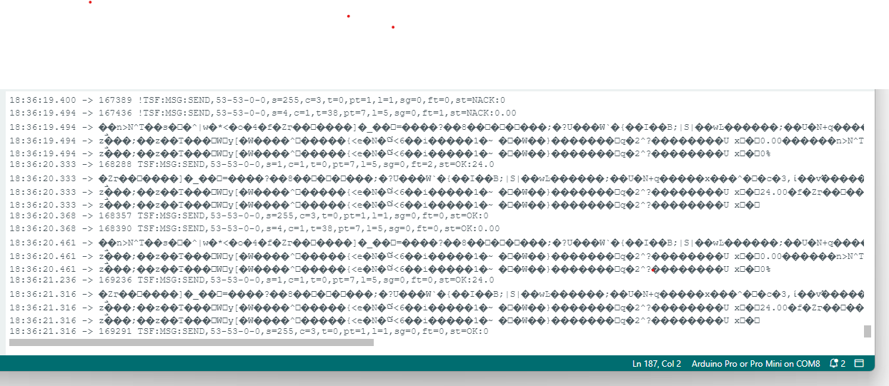
Prior to this loop there is a long run of these !MCO:PRO:RC=1 which the log parser identifies as "Recursive call detected in _process(), call level=1". These go on for many pages.
So yeah something a bit broken there Im sorry.
Nothing registered on HA =(
Have also had a go with my original code with your three suggested additions.
Is running good, domoticz has seen temp/bat/switches.
But still nothing on HA.
I have tried deleting MyS integration from HA, restarting HA, reloading MyS integration and still does not come up.
Do you think it could be because I have Domoticz listneing to the same mygw on the PI as HA? Would they compete for info or share? Beyond my level of understanding.
Perhaps I should implement a MyS serial gateway on a spare PI and connect to the HA linux box via ethernet rather than wifi and see how that goes....?Many thanks,
Matt -
Send 2x relay states to Home Assistant to make them visible?Eiten I am much obliged. Sorry for my code Ive been trying this and trying that and sort of lost track of what I done and changed.
You make it look so simple haha I just couldnt work out how to write the MyMessage and send bits thankyou so much.
Need to retire for the evening as up at 5am for work but will be back on to try it all out tomorrow, am looking forward to your next post.
Matt -
Send 2x relay states to Home Assistant to make them visible?Hi all
Been fiddling around all day. Trying to migrate from domoticz to HA.
I have an irrigation controller with two relays plus temp and bat children as well.
I cant get the relays to come up in HA although can see/use them on domoticz.
Have mys running on a pi ethernetted to a linux box with HA running as a VM. It can see my other sensors okay.
Code is rough sorry see below and TBH Im not sure which revision Im up to Ive got several .inos around but I think this is the best one. A coder I aint.
Apparently I need to "Send at least one initial value per V_TYPE. In version 2.x of MySensors, this has to be done in the loop function. See below for an example in 2.0 of how to make sure the initial value has been received by the controller" as per HA.
Is this true, does it have to be done in the main loop?
Could someone show me how to do this for BOTH relays please? They should always start in the off state...
Many many thanks in advance.
Matt/** * The MySensors Arduino library handles the wireless radio link and protocol * between your home built sensors/actuators and HA controller of choice. * The sensors forms a self healing radio network with optional repeaters. Each * repeater and gateway builds a routing tables in EEPROM which keeps track of the * network topology allowing messages to be routed to nodes. * * Created by Henrik Ekblad <henrik.ekblad@mysensors.org> * Copyright (C) 2013-2015 Sensnology AB * Full contributor list: https://github.com/mysensors/Arduino/graphs/contributors * * Documentation: http://www.mysensors.org * Support Forum: http://forum.mysensors.org * * This program is free software; you can redistribute it and/or * modify it under the terms of the GNU General Public License * version 2 as published by the Free Software Foundation. * ******************************* * * REVISION HISTORY * Version 1.0 - Henrik Ekblad * * DESCRIPTION * Example sketch showing how to control physical relays. * This example will remember relay state after power failure. * http://www.mysensors.org/build/relay */ // Enable debug prints to serial monitor #define MY_DEBUG // Enable and select radio type attached #define MY_RADIO_NRF24 //#define MY_RADIO_RFM69 // Enable repeater functionality for this node #define MY_REPEATER_FEATURE #include <SPI.h> #include <MySensors.h> #include <DallasTemperature.h> #include <OneWire.h> #define RELAY_1 4 // Arduino Digital I/O pin number for first relay (second on pin+1 etc) #define NUMBER_OF_RELAYS 2 // Total number of attached relays #define RELAY_ON 1 // GPIO value to write to turn on attached relay #define RELAY_OFF 0 // GPIO value to write to turn off attached relay #define COMPARE_TEMP 0 // Send temperature only if changed? 1 = Yes 0 = No #define MY_RF24_PA_LEVEL RF24_PA_HIGH #define ONE_WIRE_BUS 3 // Pin where dallase sensor is connected #define MAX_ATTACHED_DS18B20 1 #define CHILD_ID_BAT 9 #define CHILD_ID_TEMP 1 #define CHILD_ID_RELAY1 2 #define CHILD_ID_RELAY2 3 unsigned long SLEEP_TIME = 600000; // Sleep time between reads (in milliseconds) OneWire oneWire(ONE_WIRE_BUS); // Setup a oneWire instance to communicate with any OneWire devices (not just Maxim/Dallas temperature ICs) DallasTemperature sensors(&oneWire); // Pass the oneWire reference to Dallas Temperature. float lastTemperature[MAX_ATTACHED_DS18B20]; int numSensors=0; boolean receivedConfig = false; boolean metric = true; // Initialize temperature message MyMessage msg(CHILD_ID_TEMP, V_TEMP); MyMessage msgBat(CHILD_ID_BAT, V_VOLTAGE); //#define VBAT_PER_BITS 0.013971 #define VMIN 11 // Vmin (radio Min Volt)=1.9V (564v) #define VMAX 14.5 // Vmax = (2xAA bat)=3.0V (892v) int batteryPcnt = 0; // Calc value for battery % int BATTERY_SENSE_PIN = A0; // select the input pin for the battery sense point void before() { for (int sensor=1, pin=RELAY_1; sensor<=NUMBER_OF_RELAYS;sensor++, pin++) { // Then set relay pins in output mode pinMode(pin, OUTPUT); // Turn off all pins digitalWrite(pin, LOW); } } void setup() { analogReference(INTERNAL); // Startup up the OneWire library sensors.begin(); // requestTemperatures() will not block current thread sensors.setWaitForConversion(false); } void presentation() { // Send the sketch version information to the gateway and Controller sendSketchInfo("Relay+Temp", "1.0"); //for (int sensor=1, pin=RELAY_1; sensor<=NUMBER_OF_RELAYS;sensor++, pin++) { // Register all sensors to gw (they will be created as child devices) present(CHILD_ID_RELAY1, S_BINARY); present(CHILD_ID_RELAY2, S_BINARY); present(CHILD_ID_TEMP, S_TEMP); present(CHILD_ID_BAT, S_MULTIMETER); } // Fetch the number of attached temperature sensors //numSensors = sensors.getDeviceCount(); // Present all sensors to controller //for (int i=0; i<numSensors && i<MAX_ATTACHED_DS18B20; i++) { // present(i, S_TEMP);} //} void loop() { // Fetch temperatures from Dallas sensors sensors.requestTemperatures(); // query conversion time and sleep until conversion completed int16_t conversionTime = sensors.millisToWaitForConversion(sensors.getResolution()); // sleep() call can be replaced by wait() call if node need to process incoming messages (or if node is repeater) wait(conversionTime); // Read temperatures and send them to controller for (int i=0; i<numSensors && i<MAX_ATTACHED_DS18B20; i++) { // Fetch and round temperature to one decimal float temperature = static_cast<float>(static_cast<int>((getControllerConfig().isMetric?sensors.getTempCByIndex(i):sensors.getTempFByIndex(i)) * 10.)) / 10.; // Only send data if temperature has changed and no error #if COMPARE_TEMP == 1 if (lastTemperature[i] != temperature && temperature != -127.00 && temperature != 85.00) { #else if (temperature != -127.00 && temperature != 85.00) { #endif // Send in the new temperature send(msg.setSensor(i).set(temperature,1)); Serial.print("SensorValue"); Serial.print(temperature); // Save new temperatures for next compare lastTemperature[i]=temperature; } } int sensorValue = analogRead(BATTERY_SENSE_PIN); float Vbat = sensorValue * 0.0139644; int batteryPcnt = static_cast<int>(((Vbat-VMIN)/(VMAX-VMIN))*100.); sendBatteryLevel(batteryPcnt); send(msgBat.set(Vbat, 2)); /*Serial.print("VBat"); Serial.print(Vbat); Serial.print("SensorValue"); Serial.print(sensorValue);*/ wait(SLEEP_TIME); } void receive(const MyMessage &message) { // We only expect one type of message from controller. But we better check anyway. if (message.type==V_LIGHT) { // Change relay state digitalWrite(message.sensor-1+RELAY_1, message.getBool()?RELAY_ON:RELAY_OFF); // Store state in eeprom //saveState(message.sensor, message.getBool()); // Write some debug info Serial.print("Incoming change for sensor:"); Serial.print(message.sensor); Serial.print(", New status: "); Serial.println(message.getBool()); } } -
NewbiePCB sensors dying of old ageHi sundberg84.
Yeah you're probably right it's something to do with the boost converter eh. I'm still dead keen on battery power hence the slimnodes. Although I'll be putting 8 and 28 pun ic sockets on the pcb so I can swap out either the 328p or nrf if needed. Haven't gone down the rfm route.
I do have a single 833mhz transmitter to talk to my wall sockets has run continuously for 7 years off USB. -
Water level sensor (inches) to integrate into hardwareDunno, depends a bit on context. You could use a strain gauge underneath the cup to measure weight. Or an ultrasonic distance sensor pointing down bouncing off the water? Youd have to seal everying in silicone or epoxy due to moisture I suppose.
-
NewbiePCB sensors dying of old ageBeen a while lol Im still here though, running sundbergs PCBs around the house.
Seems the battery powered ones are dying. I used cheap chinese clones for everything. Interestingly, the ones I have running off wall sockets or USB power just keep going and going, no probs at all.
One wont get ACK or reach the controller. One I cant even talk to through the Ardunio IDE, another two wont accept uploads of new code, just sits there 'uploading' forever. another one is just dead dead, I got 3V from new batteries but nothing, nada, zip. Even my two nano's that were just sitting in a drawer for years seem to have expired. If I had a reflow oven I might give that a go as nothing to lose. I wonder if its a lead free solder thing. I have tried redoing the joints on a couple with a new tip on my hakko but made no difference. I cant really pull off/replace the NRF or pro mini as it will bugger the traces.
<shrug> lol just looked back in my emails and I ordered sundbergs PCBs in 2016 so seven years, cant expect miracles eh.
What Im gonna do now is m26872's slim nodes. I have the 328Ps and heaps of NRFs just waiting on the PCBs. As you get 10 that will mean 30(!) boards. I only ned around six but great to have spares. Programming bootloaders will be a new experience, now that my nanos have died I have also ordered an UNO to use as ISP. I think Ill just go for an 8Mhz bootloader as Im worried about issues with timing over onewire, I will be using mostly DS18B20s. Its cool that these chips have internal oscillators as well as vref so minimal components.
Sort of excited again, MySensors remains a hugely valuable app for me, thankyou Hek et al. -
Domotiocz + Rain gauge@sundberg84
Thankyou very much for your reply.
It seems strange that domoticz would only accept 1mm pulses I wonder if this has changed... In any case it should be easy to save the 'lost' volume and add it to the next bucket in code...
The internal pullup is switched on in code so reed switch pin won't be floating. Will have a fiddle round with your code today.
Will also try to calibrate by gauge today will be easy to see max tipping speed and can adjust wait times accordingly...
Thanks again,
Matt -
Domotiocz + Rain gauge@sundberg84 sorry I know this is an old thread but hoping you can remember how you wrote this code.I have changed it to suit MYS 2.1 as below. I have also added battery level as a separate child ID so I can watch performance over time. Aside from these simple changes the code is all yours from the start of this post. It is built on v8 of your board, controller/GW is latest domoticz beta running on a PI2 using NRFs.
I have a couple of questions though. I am curious as to why bucketSize needs to be 1, 0.5, 0.25, 0.2 or 0.1 as per your comments and I suspect that when I calibrate my gauge it wont be any of these.
I am testing at the moment without the gauge. When I earth D3 it actually reports as TWO bucket tips and the volume goes up by 0.5 twice. I dont think this is a bounce issue due to the many wait(1000) functions in your code. Would you know why this is? I have tried changing CHANGE to FALLING in the sleep function. I have a simple reed switch gague.
Which leads to my third question. Are all the wait times necessary? Could they be much less? I wonder if I will miss bucket tips because of these during heavy rain...
Many many thanks,
Matt// Enable debug prints to serial monitor #define MY_DEBUG #define MY_RADIO_NRF24 #define MY_RF24_PA_LEVEL RF24_PA_LOW #define MY_RF24_DATARATE RF24_250KBPS #include <MySensors.h> // Running this in Domoticz stable version 2.5 will not work - upgrade to beta. #define DIGITAL_INPUT_SENSOR 3 // The reed switch you attached. (Only 2 and 3 generates interrupt!) #define INTERRUPT DIGITAL_INPUT_SENSOR-2 // Usually the interrupt = pin -2 (on uno/nano anyway) #define CHILD_ID 1 // Id of the sensor child #define CHILD_ID_BAT 2 // Id of BAT #define SKETCH_NAME "Rain Gauge" // Change to a fancy name you like #define SKETCH_VERSION "1.1" // Your version unsigned long SLEEP_TIME = 18*60000; // Sleep time (in milliseconds). //unsigned long SLEEP_TIME = 20000; // use this instead for debug float hwRainVolume = 0; // Current rainvolume calculated in hardware. int hwPulseCounter = 0; // Pulsecount recieved from GW float fullCounter = 0; // Counts when to send counter float bucketSize = 0.5; // Bucketsize mm, needs to be 1, 0.5, 0.25, 0.2 or 0.1 boolean pcReceived = false; // If we have recieved the pulscount from GW or not boolean reedState; // Current state the reedswitch is in boolean oldReedState; // Old state (last state) of the reedswitch unsigned long lastSend =0; // Time we last tried to fetch counter. MyMessage volumeMsg(CHILD_ID,V_RAIN); MyMessage lastCounterMsg(CHILD_ID,V_VAR1); MyMessage msgBat(CHILD_ID_BAT, V_VOLTAGE); //========================= // BATTERY VOLTAGE DIVIDER SETUP // 1M, 470K divider across battery and using internal ADC ref of 1.1V // Sense point is bypassed with 0.1 uF cap to reduce noise at that point // ((1e6+470e3)/470e3)*1.1 = Vmax = 3.44 Volts // 3.44/1023 = Volts per bit = 0.003363075 #define VBAT_PER_BITS 0.003363075 #define VMIN 1.9 // Vmin (radio Min Volt)=1.9V (564v) #define VMAX 3.0 // Vmax = (2xAA bat)=3.0V (892v) int batteryPcnt = 0; // Calc value for battery % int batLoop = 0; // Loop to help calc average int batArray[3]; // Array to store value for average calc. int BATTERY_SENSE_PIN = A0; // select the input pin for the battery sense point //========================= void presentation() { // Send the Sketch Version Information to the Gateway sendSketchInfo(SKETCH_NAME, SKETCH_VERSION); // Register this device as Rain sensor (will not show in Domoticz until first value arrives) present(CHILD_ID, S_RAIN); present(CHILD_ID_BAT, S_MULTIMETER); } void setup() { // use the 1.1 V internal reference analogReference(INTERNAL); // For battery sensing pinMode(DIGITAL_INPUT_SENSOR, INPUT_PULLUP); // sets the reed sensor digital pin as input reedState = digitalRead(DIGITAL_INPUT_SENSOR); // Read what state the reedswitch is in oldReedState = reedState; // Set startup position for reedswitch Serial.println("Startup completed"); delay(500); // Allow time for radio if power used as reset } void loop() { unsigned long currentTime = millis(); //See if we have the counter/pulse from Domoticz - and ask for it if we dont. if (!pcReceived && (currentTime - lastSend > 5000)) { request(CHILD_ID, V_VAR1); lastSend=currentTime; return; } if (!pcReceived) { return; } //Read if the bucket tipped over reedState = digitalRead(DIGITAL_INPUT_SENSOR); boolean tipped = oldReedState != reedState; //BUCKET TIPS! if (tipped==true) { Serial.println("The bucket has tipped over..."); oldReedState = reedState; hwRainVolume = hwRainVolume + bucketSize; send(volumeMsg.set((float)hwRainVolume,1)); wait(1000); fullCounter = fullCounter + bucketSize; //Count so we send the counter for every 1mm if(fullCounter >= 1){ hwPulseCounter++; send(lastCounterMsg.set(hwPulseCounter)); wait(1000); fullCounter = 0; } } if (tipped==false) { //No bucket tipped over last sleep-period, check battery then... batM(); } lastSend=currentTime; sleep(INTERRUPT, FALLING, SLEEP_TIME); //The interupt can be CHANGE or FALLING depending on how you wired the hardware. } //Read if we have a incoming message. void receive(const MyMessage &msg) { if (msg.type==V_VAR1) { hwPulseCounter = msg.getULong(); hwRainVolume = hwPulseCounter; pcReceived = true; Serial.print("Received last pulse count from gw: "); Serial.println(hwPulseCounter); } } void batM(){ //The battery calculations delay(500); // Battery monitoring reading int sensorValue = analogRead(BATTERY_SENSE_PIN); delay(500); // Calculate the battery in % float Vbat = sensorValue * VBAT_PER_BITS; int batteryPcnt = static_cast<int>(((Vbat-VMIN)/(VMAX-VMIN))*100.); Serial.print("Battery percent: "); Serial.print(batteryPcnt); Serial.println(" %"); // Add it to array so we get an average of 3 (3x20min) batArray[batLoop] = batteryPcnt; if (batLoop > 1) { batteryPcnt = (batArray[0] + batArray[1] + batArray[2]); batteryPcnt = batteryPcnt / 3; if (batteryPcnt > 100) { batteryPcnt=100; } Serial.print("Battery Average (Send): "); Serial.print(batteryPcnt); Serial.println(" %"); sendBatteryLevel(batteryPcnt); send(msgBat.set(Vbat, 4)); batLoop = 0; //Sends 1 per hour as a heartbeat. send(volumeMsg.set((float)hwRainVolume,1)); send(lastCounterMsg.set(hwPulseCounter)); } else { batLoop++; } }``` -
💬 Building a Raspberry Pi Gateway@mfalkvidd Thankyou. Stable for now. Not sure if they are even genuine modules so... Can reach outside to my glasshouse even on low power setting.
If it starts playing up again I'll add verbose logging and have another look. -
💬 Building a Raspberry Pi Gateway@mfalkvidd OK have attached the logfiles below.
No clues that I can see. At 1502 the NRF goes quiet. I have tried a different pi2, different NRF (PA/LNA) and am currently running the NRF off of 5V from the PI through one of those $1.00 regulator adapter things with built in caps and such. Have also tried different PSUs including a 2A one.
Only thing I can think left to try is reducing the power output in case the high output of the radio module is inducing transients in the cables...
Am kinda stumped here. I have an arduino NRF gateway that I will try via USB if low power does not work. I have tried setting up MYSGW as LAN and USB via ./configure but the same thing happens each time.
One thought just came to me, I AM using the pin15 IRQ option on the NRF now that is still experimental?
So next time will try without IRQ and low power...Any help/suggestions greatly appreciated.
FYI I have had domoticz running on a lubuntu netbook with USB arduino NRF gateway that has been rock solid. Am trying the get a workable PI solution though, for myself and my father in law but not workable as yet sadly...At 15:02:34 you can see the last incoming node message after that the only MYSGW activity is the PING thing... which seems to happen every 10S or so. This goes on for an hour after that with no more incomings. I have ~12 sensors around the place including a power meter one which reports every minute.
15:02:29 raspberrypi dhcpcd[734]: wlan0: Router Advertisement from fe80::260:64ff:fed7:f613
Aug  5 15:02:33 raspberrypi mysgw: TSF:MSG:READ,23-23-0,s=1,c=1,t=0,pt=7,l=5,sg=0:18.0
Aug  5 15:02:33 raspberrypi mysgw: TSF:MSG:READ,23-23-0,s=0,c=1,t=1,pt=7,l=5,sg=0:21.0
Aug  5 15:02:34 raspberrypi mysgw: TSF:MSG:READ,23-23-0,s=255,c=3,t=0,pt=1,l=1,sg=0:68
Aug  5 15:02:34 raspberrypi dhcpcd[734]: wlan0: Router Advertisement from fe80::260:64ff:fed7:f613
Aug  5 15:02:36 raspberrypi mysgw: Client 0: 0;0;3;0;18;PING
Aug  5 15:02:37 raspberrypi mysgw: TSF:MSG:READ,41-7-0,s=0,c=1,t=0,pt=7,l=5,sg=0:11.6
Aug  5 15:02:41 raspberrypi dhcpcd[734]: wlan0: Router Advertisement from fe80::260:64ff:fed7:f613
Aug  5 15:02:46 raspberrypi mysgw: Client 0: 0;0;3;0;18;PING
Aug  5 15:02:50 raspberrypi dhcpcd[734]: wlan0: Router Advertisement from fe80::260:64ff:fed7:f613
Aug  5 15:02:56 raspberrypi mysgw: Client 0: 0;0;3;0;18;PING
Aug  5 15:02:57 raspberrypi dhcpcd[734]: wlan0: Router Advertisement from fe80::260:64ff:fed7:f613
Aug  5 15:03:06 raspberrypi dhcpcd[734]: wlan0: Router Advertisement from fe80::260:64ff:fed7:f613
Aug  5 15:03:06 raspberrypi mysgw: Client 0: 0;0;3;0;18;PING
Aug  5 15:03:13 raspberrypi dhcpcd[734]: wlan0: Router Advertisement from fe80::260:64ff:fed7:f613
Aug  5 15:03:16 raspberrypi mysgw: Client 0: 0;0;3;0;18;PING
Also FWIW to log from domoticz below. Ignore FANFLAG thats just a blockly flag I use...
2017-08-05 15:01:18.936 (GW) General/Voltage (FanIntakeV)
2017-08-05 15:02:04.935 (GW) General/kWh (Meter)
2017-08-05 15:02:33.940 (GW) Temp + Humidity (Mitch2)
2017-08-05 15:02:33.945 (GW) Temp + Humidity (Mitch2)
2017-08-05 15:02:37.941 (GW) Temp (MBR Fan)
2017-08-05 15:50:02.678 Set UserVariable FanFlag = 1
2017-08-05 15:51:02.693 Set UserVariable FanFlag = 1
2017-08-05 15:52:02.703 Set UserVariable FanFlag = 1
2017-08-05 15:53:02.710 Set UserVariable FanFlag = 1
2017-08-05 15:54:00.037 Set UserVariable FanFlag = 1
Thanks,
Matt -
💬 Building a Raspberry Pi Gateway@mfalkvidd OK thanks for your reply.
Have set up the -d parameter in mysgw.servie and am waiting for it to fall over again.
If I catch it I will post syslog.
Thanks,
Matt -
💬 Building a Raspberry Pi GatewayHi guys couple of questions, apologies if they have been covered elsewhere.
I am running latest dev branches of domoticz and MYS on a pi2.
At random times it seems the NRF24L01+ LNA/PA goes down, or MYS goes down and domotics stops receiving signals from all of the nodes at the same time. I have the interrupt feature enabled.
I have set the option under domoticz/hardware/data timeout to restart if no data received in five minutes but I dont think this is an ideal solution, and have yet to find out if this domoticz feature actually works in my scenario.
Any idea what causes this? I found an old thread over on the domoticz/mysensors forum but no answers there. I am using a new sd card class 10.
What I want to do is try out the different MYS builds on domoticz ie MQTT and SERIAL as well as ethernet which I am currently running. However I'm not sure how to stop the current MYS service and completely clean up the current build to start from scratch... I have tried just re entering the ./configure commands then 'make' but this does not seem to work.
Many thanks,
Matt -
Compile error for Pro Mini 5,5v 168@mfalkvidd woohoo! Time to resurrect some old nodes =)
Thanks for this... -
💬 Easy/Newbie PCB for MySensorsHad further problems with intermittent sends. Sometimes on initial presentation it only sends the sketch name and not version number. Also sends are infrequent up to six hours apart. When it does send it often only sends one child_id when there are three to send.
Previously I thought this was most likely an issue with a noisy boost converter. However I just tried replacing the 4.7uf cap on the radio with a 47uf one. Problem solved!
Matt -
💬 Easy/Newbie PCB for MySensors