Navigation

    • Register
    • Login
    • Search
    • OpenHardware.io
    • Categories
    • Recent
    • Tags
    • Popular
    1. Home
    2. Puneit Thukral
    3. Posts
    • Profile
    • Following
    • Followers
    • Topics
    • Posts
    • Best
    • Groups

    Posts made by Puneit Thukral

    • RE: Where did everyone go?

      I have said this before (I do not know where) but here it is again.
      One of the reasons that MySensors didn't become as popular as other frameworks is because it somewhat matured before YouTubers were popular. Today, fewer people like to read, and most like to watch a YouTube video sitting on the toilet. The YouTubers not only provide step by step instructions, they do live streams and then there are Discord servers.

      I myself manage a small discord server on Home Automation and I see everyday newbies coming in and they are looking for a magical cheap solution which somehow works.
      The barrier for entry into MySensors is big (involves a lot more wires, it does not seem sexy, no one talks about it on YouTube). On the other hand, everyone has an ISP given All-In-One router+AP+DHCP server and ESPs simply connect to them. Everyday Amazon, AliExpress etc are flooding the market with Wifi based products, so the time for feeling of gratification is very small. You buy, plug in, use the app and it works

      That said, we do have a dedicated MySensors channel on our discord server and I have been pushing (literally) people to try MySensors. Serious DIYers are still interested and I have successfully introduced 4 people to it, 2 have started using it.

      I won't call the Mysensors a stagnant or dying breed but the concept of forums in my opinion is. Forums are still the most structured support system (I am not saying otherwise) but many people want instant answers, - they do not want to make the effort asking a good question. And across many forums which have been there for a few years, a common answer is "search before you ask".

      This is my two cents on this topic

      posted in General Discussion
      Puneit Thukral
      Puneit Thukral
    • RE: Best password manager?

      I moved from keepass to Bitwarden self hosted. For a while I used both in parallel and now I have fully moved to Bitwarden self hosted. It integrates very well with everything- iOS, Safari on Mac and other browsers

      posted in General Discussion
      Puneit Thukral
      Puneit Thukral
    • RE: Advisory: put IOT devices on a separate LAN/vLAN for better security

      @NeverDie creating VLANs and restricting access of the IOT devices to must have access is the method I follow.

      posted in General Discussion
      Puneit Thukral
      Puneit Thukral
    • RE: [Answered] Any recommended load-and-go VM or Docker images for mysensors?

      @jkandasa I am yet to use to Serial2Mqtt in order to test this out without breaking my current setup.. I will do it and share my feedback. I would definitely want to run Mycontroller in parallel to HA.

      posted in Controllers
      Puneit Thukral
      Puneit Thukral
    • RE: [Answered] Any recommended load-and-go VM or Docker images for mysensors?

      @NeverDie MySensors via UI came in this release 2021.3. Prior to that it was through an entry (very simple one) in configuration.yaml.

      If you have cameras, 3D printer (running Klipper) - all that can come into HA. And Homekit via HA works great as well.

      posted in Controllers
      Puneit Thukral
      Puneit Thukral
    • RE: [Answered] Any recommended load-and-go VM or Docker images for mysensors?

      @NeverDie VM install is one with the supervisor.. yes this is what I was referring to. VM is one of the supported methods, I guess

      posted in Controllers
      Puneit Thukral
      Puneit Thukral
    • RE: [Answered] Any recommended load-and-go VM or Docker images for mysensors?

      @NeverDie While I never used proxmox or VM, I did use the supervised install on Linux and then moved away from it. The advantage of supervised install is that you get the addon store but the disadvantage is that Supervisors starts to complain and moan as you install more containers on the host system.
      It then stops you from upgrading to latest versions and prevents addons to be updated. At that stage I decided to move away from a supervised install.

      posted in Controllers
      Puneit Thukral
      Puneit Thukral
    • RE: 💬 Capacitive Soil Moisture Sensor

      @Ron @Anticimex The radio stops at 1.9V.. so I think its fair to do a BOD of 1.8V.

      I used arduinoAsISP to burn bootloader and this is my platformio.ini

      [env:program_via_ArduinoISP]
      platform = atmelavr
      framework = arduino
      ;  Serial bootloader protocol
      upload_protocol = custom
      ; Serial upload port
      upload_port = /dev/cu.*
      ; Get upload baud rate defined in the fuses_bootloader environment
      upload_speed = 19200
      board_build.f_cpu = 8000000L
      board_hardware.oscillator = internal
      board_hardware.uart = uart0
      board_hardware.bod = 1.8v
      board_hardware.eesave = yes
      board_hardware.ckout = no
      upload_flags =
          -C
          ; use "tool-avrdude-megaavr" for the atmelmegaavr platform
          /Users/puneit/Nextcloud/PlatformIO/bootloader/tool-avrdude/avrdude2.conf
          -p
          $BOARD_MCU
          -P
          $UPLOAD_PORT
          -b
          $UPLOAD_SPEED
          -c
          stk500
      upload_command = avrdude $UPLOAD_FLAGS -U flash:w:$SOURCE:i
      
      posted in OpenHardware.io
      Puneit Thukral
      Puneit Thukral
    • RE: [Answered] Any recommended load-and-go VM or Docker images for mysensors?

      @ncollins Yes, it is very easy to (re)deploy a whole system using the docker compose files.
      I have 4 splits --- one being my core containers , Homeassistant, Nodered, Mosquitto, etc and then one of them being "applications that I don't need but have".. I recently had to redeploy and my core stack was running in under 10 minutes..

      It is a very powerful tool.

      posted in Controllers
      Puneit Thukral
      Puneit Thukral
    • RE: 💬 Capacitive Soil Moisture Sensor

      Hi great design... If I can suggest one improvement, it would be to burn a minicore bootloader and set BOD to 1.8V so that the batteries can last longer.

      posted in OpenHardware.io
      Puneit Thukral
      Puneit Thukral
    • RE: [Answered] Any recommended load-and-go VM or Docker images for mysensors?

      Home assistant has a docker container which talks nicely with a mysensors serial gateway connected via USB on a Dell machine.

       homeassistant:
          container_name: hass
          image: homeassistant/home-assistant:stable
          volumes:
            - /home/server/homeassistant/:/config
            - /etc/localtime:/etc/localtime:ro
            - /var/run/docker.sock:/var/run/docker.sock
          restart: unless-stopped
          devices:
            - /dev/ttyUSB0:/dev/ttyUSB0:rwm
          healthcheck:
            test: ["CMD", "curl", "-f", "http://127.0.0.1:8123"]
            interval: 30s
            timeout: 10s
            retries: 6
          network_mode: host
          depends_on: 
            - mosquitto
      

      the following line enables serial gateway into HA and then in the latest release 2021.3 one can add Mysensors from UI

      devices:
            - /dev/ttyUSB0:/dev/ttyUSB0:rwm
      
      posted in Controllers
      Puneit Thukral
      Puneit Thukral
    • RE: GUIDE - NRF5 / NRF51 / NRF52 for beginners

      @monte Could you please share the custom sleep function?

      posted in Development
      Puneit Thukral
      Puneit Thukral
    • RE: Your suggestions to choose naming for "sensor" and "variable"

      Hello @jkandasa
      This is looking very good. Nomenclarture wise - I am of the opnion that users adapt but if you ask me I like sensor over element (but I can live with element as well).

      In future will it be possible port this to mobile apps for iOS and Android?

      One integration I would request is for HomeKit.

      Thank you

      posted in MyController.org
      Puneit Thukral
      Puneit Thukral
    • RE: GUIDE - NRF5 / NRF51 / NRF52 for beginners

      @ncollins It is possible to use NRF51822 for gateways with serial. I am using it for many months now. We need USB to serial adapter.
      Also, I do not use JLink or ST-Link for flashing the NRF51 chips. I use raspberry pi with OpenOCD.
      OpenOCD setup can be overwhelming (it was for me) but I have been able to make it work and replicate for a while now. If someone needs inputs, I am happy to help. Ask here or reach out to me on discord @ Puneit#2433

      For the very reason you stated - hardware bugs in NR51 chips leading to high power-consumption - they make compact repeater nodes / powered nodes with repeaters.

      posted in Development
      Puneit Thukral
      Puneit Thukral
    • RE: cant add two relays in the Home assistant

      Hello
      It could be a case of presentation being done too fast. Add a wait(50) like this

       // Present all relays to controller
        for (int sensor=CHILD_ID_RELAY, pin=RELAY_1; sensor<CHILD_ID_RELAY+NUMBER_OF_RELAYS;sensor++, pin++) {
          // Register all sensors to gw (they will be created as child devices)
          present(sensor, S_LIGHT);
           wait( 50 ); // <--- byTheo
      
      posted in Troubleshooting
      Puneit Thukral
      Puneit Thukral
    • RE: 💬 Battery Powered Sensors

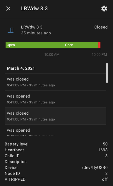
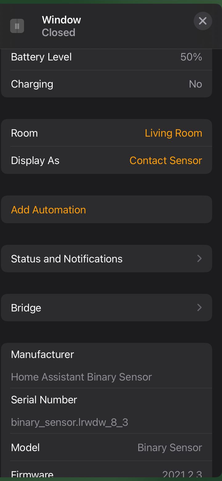
      Adding on to this.. If we use a map function to convert the battery level like this, then it shows up as an attribute in HomeAssistant and Homekit

      Map function works and not the percent. The percent always shows as zero in Homekit.
      Hope this helps someone!

      void battery()
      {
        long batteryMillivolts = hwCPUVoltage();
        int batteryV =batteryMillivolts /1000 + 0.5;
        auto batteryLevel = map(batteryV,EMPTY_BATTERY, FULL_BATTERY, 0, 100);
        if (batteryLevel > 100) 
        {batteryLevel=100;}
      
      #ifdef MY_DEBUG
        Serial.print("Battery voltage: ");
        Serial.print(batteryMillivolts / 1000.0);
        Serial.println("V");
        Serial.print("Battery Level ");
        Serial.print(batteryLevel);
        Serial.println(" %");
      #endif
      
        if (oldBatteryLevel != batteryLevel) {
          sendBatteryLevel(batteryLevel);
          send(msgV.set(batteryV,2));
          oldBatteryLevel = batteryLevel;
        }
      }
      

      ![Home Assistant](812c9e02-8b21-44dc-ab8d-04559bf38462-image.png image url)

      IHomeKit

      posted in Announcements
      Puneit Thukral
      Puneit Thukral
    • RE: Nrf5x on NodeManager

      @Francisco_Elias Not using node manager but this sketch. See if it helps you

      //#define MY_DEBUG //Debug Disabled in production
      #define MY_RADIO_NRF5_ESB
      //#define MY_NODE_ID 10 // change this for every node
      #define SKETCH_NAME "Door Sensor" // this can be changed as well
      #define SKETCH_VERSION "V1"
      #define MY_SMART_SLEEP_WAIT_DURATION 500 //activate smart sleep
      #define MY_SLEEP_TRANSPORT_RECONNECT_TIMEOUT_MS  10000 //wait for 10 seconds to reconnect in case of transport problems
      #define MY_TRANSPORT_WAIT_READY_MS 30000  //try connecting for 30 seconds
      //#define MY_PARENT_NODE_ID 0
      //#define MY_PARENT_NODE_IS_STATIC


      #define DIGITAL_INPUT_SENSOR 2       // The digital input you attached your Door/Window sensor.
      #define CHILD_ID_DOOR 1            // Id of the door/window sensor child.
      #define CHILD_ID_BATTERY 254      // ID of the battery sensor
      #define BATTERY_FULL          3    // 
      #define BATTERY_EMPTY         1.8    // NRF51822 does not work below 1.8V
      float BATTERY_FULL_PCNT=100;    // 
      float BATTERY_EMPTY_PCNT=0;    // NRF51822 does not work below 1.8V
      #include <MySensors.h>


      #ifdef MY_DEBUG
      uint32_t SLEEP_TIME = 30000; // when debugging, sleep time is 30 seconds
      #endif
      #ifndef MY_DEBUG
      
        uint32_t SLEEP_TIME = 60000 * 1440 ; // when deployed, sleep time is 30 minutes
      #endif
      
      #define SHORT_WAIT 500  
      
      bool oldValueDoor = -1;
      float batteryVoltage = 0;
      //bool tripped=2;
      // Initialize door/window message
      MyMessage msgDoor(CHILD_ID_DOOR, V_TRIPPED); //Door/Window.
      
      MyMessage msgBattery(CHILD_ID_BATTERY, V_VOLTAGE);
      int batteryPcnt=-1;
      void setup()
      {
      
        pinMode(DIGITAL_INPUT_SENSOR, INPUT_PULLUP);  // sets the door/window sensor digital pin as input
        digitalWrite(DIGITAL_INPUT_SENSOR, HIGH);
      }
      void presentation()
      {
      
        sendSketchInfo(SKETCH_NAME, SKETCH_VERSION);
      
        present(CHILD_ID_DOOR, S_DOOR, "Door");
        wait(SHORT_WAIT);
        present(CHILD_ID_BATTERY, S_MULTIMETER, "DoorBatt");
      
      }
      
      void loop()
      {
        
        bool tripped = digitalRead(DIGITAL_INPUT_SENSOR)==HIGH;
      
        if (tripped != oldValueDoor)
        {
      
      
          send(msgDoor.set(tripped ? "1" : "0"), true); // Send door/window tripped value to gw
      
          oldValueDoor = tripped;
        }
         
      
          batteryVoltage = ((float)hwCPUVoltage()) / 1000.0;
          
          send(msgBattery.set(batteryVoltage, 2)); //this creates a voltage sensor
          batteryPcnt = round((batteryVoltage - BATTERY_EMPTY) *100.0 / (BATTERY_FULL - BATTERY_EMPTY));
          if (batteryPcnt > 100) {batteryPcnt = 100;}
         if (batteryPcnt <= 0) {batteryPcnt = 0;} 
          sendBatteryLevel(batteryPcnt, true); // this adds attribute to the door sensor
          sendHeartbeat();
              batteryPcnt=0;
      
          smartSleep(digitalPinToInterrupt(DIGITAL_INPUT_SENSOR), CHANGE, SLEEP_TIME);
          
      
      }
      
      posted in NodeManager
      Puneit Thukral
      Puneit Thukral
    • RE: Ds18b20/ nodemcu fluctuations in temp

      @mjdula
      This is not a support forum for Tasmota. You should try their Discord

      posted in Hardware
      Puneit Thukral
      Puneit Thukral
    • RE: Question about MySensors features

      @IronFelix
      I would not combine so many inputs and outputs in one sketch. But I think if there is enough memory for variables ; then it is possible to go for sensing (step by step) for a combination of sensors.
      Similarly for buttons, actuators, use a separate hardware.

      posted in My Project
      Puneit Thukral
      Puneit Thukral
    • RE: sending an image without wifi / envoi d'une image hors wifi

      Very interesting requirement. In the world of amateur radio, this is possible using SSTV (Slow Scan TV ) on frequency bands like VHF or UHF. But then this is not encrypted and anyone with a receiver and hardware can receive and decode these signals.

      https://en.wikipedia.org/wiki/Slow-scan_television

      Now, if it can be done with NRF24l01 or with RFM69, I do not know. Back in the day, people were sending multimedia over Bluetooth so maybe that works for you.

      posted in Hardware
      Puneit Thukral
      Puneit Thukral
    • RE: pinout for waveshare 1.54 inch e-paper on fanstel BT832X

      Hello
      Have a look at this
      https://forum.mysensors.org/post/88732

      posted in Hardware
      Puneit Thukral
      Puneit Thukral
    • RE: Ethernet Gateway and FOTA

      @Jan-Spies
      From what I know - MySController only works with serial and/or Ethernet. Mqtt is not supported. May you can try with Ethernet only gateway.

      posted in Troubleshooting
      Puneit Thukral
      Puneit Thukral
    • RE: 💬 Battery Powered Sensors

      @Sebex Will this help
      https://grabcad.com/library/arduino-pro-mini-1
      and should we move this conversation to another topic /PM as this is not relevant to this thread.

      posted in Announcements
      Puneit Thukral
      Puneit Thukral
    • RE: SCT013 50A - Low current

      I think you can try this

      posted in Hardware
      Puneit Thukral
      Puneit Thukral
    • RE: 💬 Battery Powered Sensors

      @Sebex Do share the STL - it will be great and if you use Fusion360, then may I request for the F3D file.. I am semi-skilled when it comes to designing

      posted in Announcements
      Puneit Thukral
      Puneit Thukral
    • RE: SCT013 50A - Low current

      @carlos-sampaio said in SCT013 50A - Low current:

      SCT013

      I would be interested to know this as well, but to my understanding - maybe it has something to do with resolution. I had earlier used this calculator to calculate the value of resistors and capcitors for my 30A CT Clamp. But the calculator is no longer opening.

      There are lower capacity CT clamps available and perhaps those can measure smaller currents. It is possible that the mA current is smaller than the threshold to excite the coil inside it.

      posted in Hardware
      Puneit Thukral
      Puneit Thukral
    • Low Power LED detection : Voltage Divider or RC Time?

      Hello
      I have a smart meter in my apartment on which an LED glows when the power supply switches from the grid to a backup ( in case of load shedding etc).
      Today, I use an Nodemcu running ESPhome to detect the LED glowing on or off status by doing a voltage divider on a LDR. This is being powered through a phone charger. I check the status on a digital pin.

      Now, in order to improve the WAF points, I need to make is battery operated (wires are ugly - simple), hence I would like to run it on Arduino Pro mini running MySensors & AA/AAA batteries
      Which is more power efficient - LDR with voltage divider or LDR with a capacitor using the rctime library?
      Year to date LED was on 103 hours

      0dbaf16e-8b71-4e80-a4ba-1275e6156f6f-image.png

      posted in Development
      Puneit Thukral
      Puneit Thukral
    • RE: V_UNIT_PREFIX not working/recognised for Air Quality sensor CSS811

      Hi @Sebex , I followed @BearWithBeard advise (thank you) and customised the entity in home assistant. And now it shows as numbers. 39b5668a-ba4f-4bca-b6b0-1115e7f7eb11-image.png

      posted in Troubleshooting
      Puneit Thukral
      Puneit Thukral
    • RE: V_UNIT_PREFIX not working/recognised for Air Quality sensor CSS811

      @Sebex How is V_PRESSURE being shown in Home Assistant. For me it is showing as a Text instead of a number. Is it the same for you?
      26abdcbe-6bbb-49d5-9676-4d22c8646b7f-image.png

      posted in Troubleshooting
      Puneit Thukral
      Puneit Thukral
    • RE: 💬 Battery Powered Sensors

      @Sebex Yes, I 3D printed on my ender 3 and I am using this on nodemcu running ESPhome. But I did not design it. Here is the Thingiverse link to it.
      Nodemcu case

      I would love to do similar case and a larger case like this to fit other boards. Its rock solid. I do not have skills to make a linear pattern like this. I think I should figure out how to do it.

      posted in Announcements
      Puneit Thukral
      Puneit Thukral
    • RE: 💬 Battery Powered Sensors

      @Sebex yes, of course. I have done that as well. In case I need to repurpose something , removing solder completely away is a tougher job for me than peeling away a layer of glue. Guess, I am just lazy. 😃

      posted in Announcements
      Puneit Thukral
      Puneit Thukral
    • RE: Looking for a door monitor setup/circuit

      @jamzm From what I understood is that a Fing box is an interface device which adds to your router and it is something related to the WiFi network.

      I am no expert - -still loads to learn but then I think there is some disconnect. While the Mysensors network does work on the 2.4GHz frequency range (through the NRF24 or NRF5 radios), the network is an ISM band network and not a WiFi standard. Therefore you need to add a gateway from the door sensor to your network.

      Take a look at the Getting Started and Build pages.

      The minimum you need is a arduino board of your choice with a radio of your choice for the sensor; an arduino/esp8266 of your choice and the same radio for the gateway and a controller of your choice as well.

      Had I been starting and someone asked me to choose a bunch of stuff, I would get scared. So I will tell you what I use.. its just one of the implementations.

      For the sensors I use arduino pro mini 3.3v with NRF24L01 and I am experimenting with NRF51822 (stay away from these)
      For the gateway, I use an arduino uno with NRF24l01 with an ethernet shield running MQTT gateway
      For the controller I use Home Assistant.

      Now for the sensor itself - if you want to DIY the same, then I would do it this way (again different people would have different methods)

      Use arduino pro-mini with NRF24l01 and a reed-switch. 3D print the case for it and use it.

      I hope I was able to help in some manner.

      posted in General Discussion
      Puneit Thukral
      Puneit Thukral
    • RE: Just found a pair of "old" NRF51822-04 ... any good?

      @Jokgi for sure , next purchase for me would be the nrf52 series. As with @ghiglie , I too had bought the nrf51822 many years back and they were sitting in the drawer. This lockdown allowed me to discover them and hence I decided to use them.

      posted in Hardware
      Puneit Thukral
      Puneit Thukral
    • RE: 💬 Battery Powered Sensors

      @skywatch Agree with every word of yours. Not justifying myself here but wirewraps are deployed all over my house. I pour some hot glue to ensure that they don’t come loose. And then a 3D printed enclosure takes care of the elements.
      Also, it helps me to quickly repurpose the hardware.
      It’s just another approach.
      In an ideal world - where PCB shipments never arrive from China and locally they are a but expensive , this is my poor man’s alternative. 90F6D2B8-A1BA-4156-A23E-B7783A89FA49.jpeg 97A8362E-7B49-433F-8709-42E49469B161.jpeg Example photos. The coin cell holder is diy. Used shaving blades and wrapped wires and taped to create a circuit.

      posted in Announcements
      Puneit Thukral
      Puneit Thukral
    • RE: Reed Switch normally open or normally closed

      @skywatch thanks a lot for offering to help. I think I have made some headway.
      I used @NeverDie sketches. The one for nrf24 or RFM69 don’t really work well with waking up the nrf51 chip or maybe I made some mistake and were consuming way too much power.

      Anyhow , the test sketch is running and interrupts are working fine as well as the bme280 reports fine.
      Tomorrow I will move it a battery powered and observe.

      Cheers!

      posted in Hardware
      Puneit Thukral
      Puneit Thukral
    • RE: Newbie question about Sending sensor data with an nRF52832 module to my sensors

      @tBS You should try the low power sketches by @NeverDie or @berkseo - They are available on openhardware.io

      posted in Hardware
      Puneit Thukral
      Puneit Thukral
    • RE: Just found a pair of "old" NRF51822-04 ... any good?

      @Holosteric & @ghiglie I am actively working on the NRF51822. I am testing @NeverDie 's PIR and Temp/Humidity sketches. The example sketches of Mysensors didn't work well for me.
      I will report the results.
      Main sketch

      // SUMMARY: This demo sketch runs on the AM612 PIR v607 PCBto transmit battery voltage (heartbeat) and motion detections to a MySensors gateway using MySensors protocols.
      
      // Note: because this is a passive node, node ID must be set manually to a unique sensor node ID:
      #define MY_NODE_ID 143  // Passive mode requires static node ID
      
      //#define MY_CORE_ONLY
      
      #define MY_PASSIVE_NODE
      
      #define MY_RADIO_NRF5_ESB
      
      #define IS_NRF51  //true iff the target is an nRF51.  If an nRF52, then comment this line out!
      
      
      #define PIR_DETECTION_PIN 2 
      #define SHORT_WAIT 50
      
      #include <MySensors.h>
      //#include <Wire.h>
      #include <Adafruit_BME280.h>
      
      // Enable debug prints
      //#define MY_DEBUG
      
      
      volatile bool motion_change=false;
      
      Adafruit_BME280 bme; // use I2C interface
      Adafruit_Sensor *bme_temp = bme.getTemperatureSensor();
      Adafruit_Sensor *bme_pressure = bme.getPressureSensor();
      Adafruit_Sensor *bme_humidity = bme.getHumiditySensor();
      
      void disableNfc() {  //only applied to nRF52
      
      #ifndef IS_NRF51
        //Make pins 9 and 10 usable as GPIO pins.
        NRF_NFCT->TASKS_DISABLE=1;  //disable NFC
        NRF_NVMC->CONFIG=1;  // Write enable the UICR
        NRF_UICR->NFCPINS=0; //Make pins 9 and 10 usable as GPIO pins.
        NRF_NVMC->CONFIG=0;  // Put the UICR back into read-only mode.
      #endif
      }
      
      
      void turnOffRadio() {
        NRF_RADIO->TASKS_DISABLE=1;
        while (!(NRF_RADIO->EVENTS_DISABLED)) {}  //until radio is confirmed disabled
      }
      
      void turnOffUarte0() {
      #ifndef IS_NRF51  
        NRF_UARTE0->TASKS_STOPRX = 1;
        NRF_UARTE0->TASKS_STOPTX = 1;
        NRF_UARTE0->TASKS_SUSPEND = 1;
        NRF_UARTE0->ENABLE=0;  //disable UART0
        while (NRF_UARTE0->ENABLE!=0) {};  //wait until UART0 is confirmed disabled.
      #endif
      
      #ifdef IS_NRF51
        NRF_UART0->TASKS_STOPRX = 1;
        NRF_UART0->TASKS_STOPTX = 1;
        NRF_UART0->TASKS_SUSPEND = 1;
        NRF_UART0->ENABLE=0;  //disable UART0
        while (NRF_UART0->ENABLE!=0) {};  //wait until UART0 is confirmed disabled.
      #endif
      }
      
      void turnOffAdc() {
      #ifndef IS_NRF51
        if (NRF_SAADC->ENABLE) { //if enabled, then disable the SAADC
          NRF_SAADC->TASKS_STOP=1;
          while (NRF_SAADC->EVENTS_STOPPED) {} //wait until stopping of SAADC is confirmed
          NRF_SAADC->ENABLE=0;  //disable the SAADC
          while (NRF_SAADC->ENABLE) {} //wait until the disable is confirmed
        }
      #endif
      }
      
      
      void turnOffHighFrequencyClock() {
          NRF_CLOCK->TASKS_HFCLKSTOP = 1;
          while ((NRF_CLOCK->HFCLKSTAT) & 0x0100) {}  //wait as long as HF clock is still running.
      }
      
      
      void mySleepPrepare() {  //turn-off energy drains prior to sleep
        turnOffHighFrequencyClock();
        turnOffRadio();
        turnOffUarte0();
      }
       
      
      void activateLpComp() {
        NRF_LPCOMP->PSEL=3; // monitor AIN0 (i.e. pin P0.02 on nRF52832 PIR Motion Sensor v607).
        while (!(NRF_LPCOMP->PSEL==3)) {} //wait until confirmed
        NRF_LPCOMP->REFSEL=3;  // choose 1/2 VDD as the reference voltage
        while (!(NRF_LPCOMP->REFSEL==3)) {} //wait until confirmed
        NRF_LPCOMP->ANADETECT=0;  //detect CROSS events on PIR detection pin
        while (NRF_LPCOMP->ANADETECT!=0) {} //wait until confirmed
        NRF_LPCOMP->INTENSET=B1000;  //Enable interrupt for CROSS event
        while (!(((NRF_LPCOMP->INTENSET)&B1000)==B1000)) {} //wait until confirmed
        NRF_LPCOMP->ENABLE=1;  //Enable LPCOMP
        while (!(NRF_LPCOMP->ENABLE==1)) {} //wait until confirmed
        NRF_LPCOMP->TASKS_START=1;  //start the LPCOMP
        while (!(NRF_LPCOMP->EVENTS_READY)) {}  //wait until ready
        
        NVIC_SetPriority(LPCOMP_IRQn, 15);
        NVIC_ClearPendingIRQ(LPCOMP_IRQn);
        NVIC_EnableIRQ(LPCOMP_IRQn);
      }
      
      void suspendLpComp() { //suspend getting more interrupts from LPCOMP before the first interrupt can be handled
        if ((NRF_LPCOMP->ENABLE) && (NRF_LPCOMP->EVENTS_READY)) {  //if LPCOMP is enabled
          NRF_LPCOMP->INTENCLR=B0100;  //disable interrupt from LPCOMP
          while (((NRF_LPCOMP->INTENCLR)&B0100)==B0100) {} //wait until confirmed
        }
      }
      
      void resumeLpComp() { //suspend getting interrupts from LPCOMP
        NRF_LPCOMP->INTENSET=B0100;  //Enable interrupt for UP event
        while (((NRF_LPCOMP->INTENSET)&B1000)!=B0100) {} //wait until confirmed
      }
      
      
      #define CHILD_ID 1   // Id of the motion sensor child
      #define ID_S_MULTIMETER        28
      #define CHILD_ID_TEMP 2
      #define CHILD_ID_HUMID 3
      #define CHILD_ID_BARO 4
      // Initialize motion message
      
      MyMessage msg(CHILD_ID, V_TRIPPED);
      MyMessage msg_S_MULTIMETER_V_VOLTAGE(ID_S_MULTIMETER,V_VOLTAGE);
      MyMessage msgTemp(CHILD_ID_TEMP, V_TEMP);
      MyMessage msgHumid(CHILD_ID_HUMID, V_HUM);
      MyMessage msgPressure(CHILD_ID_BARO, V_PRESSURE);
      
      float batteryVoltage=0;  
      float temperature=0;
      int humidity=0;
      float pressure=0;


      void presentation()
      {
        // Send the sketch version information to the gateway and Controller
        sendSketchInfo("PIR BME Sensor", "1.0");
      
        // Register all sensors to gw (they will be created as child devices)
        present(CHILD_ID, S_MOTION);
      
        wait(SHORT_WAIT);
        
        present(ID_S_MULTIMETER,S_MULTIMETER,"Electric Station");
        wait(SHORT_WAIT);
        present(CHILD_ID_TEMP, S_TEMP, "PIR TEST Temperature", true);
        wait(SHORT_WAIT);
        present(CHILD_ID_HUMID, S_HUM, "PIR TEST Humidity", true);
        wait(SHORT_WAIT);
        present(CHILD_ID_BARO, S_BARO, "PIR TEST Pressure", true);
        wait(SHORT_WAIT);
      }
      
      
      void setup()
      {
        hwInit();
      
        hwPinMode(PIR_DETECTION_PIN,INPUT);
         if (!bme.begin(0x76))
        {
          while (1) delay(100);
      
        }
        disableNfc();  //remove unnecessary energy drains
        turnOffAdc();  //remove unnecessary energy drains
        activateLpComp();
        NRF_CLOCK->INTENSET=B11;  //enable interrupts for EVENTS_HFCLKSTARTED and  EVENTS_LFCLKSTARTED
        NRF_CLOCK->TASKS_HFCLKSTART=1;  //start the high frequency crystal oscillator clock
        while (!(NRF_CLOCK->EVENTS_HFCLKSTARTED)) {} //wait until high frequency crystal oscillator clock is up to speed and working
      
        motion_change=false;
      }


      void mySleep(uint32_t ms) {
         mySleepPrepare();  //Take steps to reduce drains on battery current prior to sleeping
         sleep(ms);
      }
      
      
      bool motionDetected=false;
      void loop() {
      //    sensors_event_t temp_event, pressure_event, humidity_event;
      //    bme_temp->getEvent(&temp_event);
      //    bme_pressure->getEvent(&pressure_event);
      //    bme_humidity->getEvent(&humidity_event);
      //    temperature=bme.readTemperature();
      //    humidity=bme.readHumidity();
      //    pressure=bme.readPressure()/100.0F;
        mySleep(300000);  //sleep for 5 minutes
      
        if (motion_change) {
          motionDetected=!motionDetected;
          if (motionDetected) {
      //      digitalWrite(LED_BUILTIN,HIGH);  //turn-on LED to signify motion detected
            send(msg.set("1"));  // motion detected
          }
          else {
      //      digitalWrite(LED_BUILTIN,LOW);  //turn-off LED to signify motion no longer detected
            send(msg.set("0"));  // send all-clear to prepare for future detections
          }    
          
          NRF_LPCOMP->EVENTS_CROSS=0;
          motion_change=false;
        }
        else { //must be a scheduled wake-up.  Time to report voltage as a heartbeat.
          
      
          sensors_event_t temp_event, pressure_event, humidity_event;
          bme_temp->getEvent(&temp_event);
          bme_pressure->getEvent(&pressure_event);
          bme_humidity->getEvent(&humidity_event);
          temperature=bme.readTemperature();
          humidity=bme.readHumidity();
          pressure=bme.readPressure()/100.0F;
          wait(100);
          send(msgTemp.set(temperature,2));
          wait(100);
          send(msgHumid.set(humidity,2));
          wait(100);
          send(msgPressure.set(pressure,2));
          wait(100);
      
        batteryVoltage=((float)hwCPUVoltage())/1000.0;  //take voltage measurement after transmission to hopefully measure lowest voltage that occurs. 
          send(msg_S_MULTIMETER_V_VOLTAGE.set(batteryVoltage,3));  //send battery voltage with 3 decimal places


        }
      }
      
      
      // * Reset events and read back on nRF52
      //* http://infocenter.nordicsemi.com/pdf/nRF52_Series_Migration_v1.0.pdf
       
      #if __CORTEX_M == 0x04
      #define NRF5_RESET_EVENT(event)                                                 \
              event = 0;                                                                   \
              (void)event
      #else
      #define NRF5_RESET_EVENT(event) event = 0
      #endif
      
      
      // This must be in one line
      extern "C" { void LPCOMP_IRQHandler(void) {motion_change=true; NRF5_RESET_EVENT(NRF_LPCOMP->EVENTS_CROSS); NRF_LPCOMP->EVENTS_CROSS=0; MY_HW_RTC->CC[0]=(MY_HW_RTC->COUNTER+2);}}
      

      MyBoardNRF5.cpp

      /*
        If you don't use an nRF5 board, you can ignore this file.
        
        This file was part of the "My Sensors nRF5 Boards" board repository
        available at https://github.com/mysensors/ArduinoBoards If you have
        questions, please refer the documentation at
        https://github.com/mysensors/ArduinoHwNRF5 first.
        
        This file is compatible with ArduinoHwNRF5 >= 0.2.0
      
        This file allows you to change the relation between pins referenced in
        the Arduino IDE (0..31) and pins of the nRF5 MCU (P0.00..P0.31).
        
        If you can live with addressing the GPIO pins by using the Arduino pins
        0..31 instead of a custom mapping, don't change this file. If you have
        a lot of Arduino code with fixed pin numbers and you need to map these
        pins to specific pins of the nRF5 MCU; you need to change this file.
        
        If you fill the "g_APinDescription" Array with numbers between 0..31,
        the Arduino pins 0..31 are assigned to pins P0.00..P0.31 of the MCU.
        
        As an example, if you need to change the pin mapping for Arduino pin 5
        to P0.12 of the MCU, you have to write the 12 after PORT0 into the sixth
        position in the  "g_APinDescription" Array.
         
        The extended attributes only affects the nRF5 variants provided with
        official Arduino boards. The arduino-nrf5 variant ignores the extended
        attributes.
          
        The pin mapping effects commands like "pinMode()", "digitalWrite()",
        "analogRead()" and "analogWrite()".
        
        If you change the pin mapping, you have to modify the pins in
        "MyBoardNRF5.h". Especially the analog pin mapping must be replaced with
        your pin numbers by replacing PIN_AIN0..7 with a number of your mapping
        array. You can use the constants PIN_AIN0..7 in the "g_APinDescription"
        Array if you want to reference analog ports MCU independent. You cannot
        use the pins P0.00 and P0.01 for GPIO, when the 32kHz crystal is connected.
      
        
        ###########################################################################
      
        Copyright (c) 2014-2015 Arduino LLC.  All right reserved.
        Copyright (c) 2016 Arduino Srl.  All right reserved.
        Copyright (c) 2017 Sensnology AB. All right reserved.
      
        This library is free software; you can redistribute it and/or
        modify it under the terms of the GNU Lesser General Public
        License as published by the Free Software Foundation; either
        version 2.1 of the License, or (at your option) any later version.
      
        This library is distributed in the hope that it will be useful,
        but WITHOUT ANY WARRANTY; without even the implied warranty of
        MERCHANTABILITY or FITNESS FOR A PARTICULAR PURPOSE.
        See the GNU Lesser General Public License for more details.
      
        You should have received a copy of the GNU Lesser General Public
        License along with this library; if not, write to the Free Software
        Foundation, Inc., 51 Franklin St, Fifth Floor, Boston, MA  02110-1301  USA
      */


      #ifdef MYBOARDNRF5
      #include <variant.h>
      
      /*
       * Pins descriptions. Attributes are ignored by arduino-nrf5 variant. 
       * Definition taken from Arduino Primo Core with ordered ports
       */
      const PinDescription g_APinDescription[] =
      {
        { NOT_A_PORT, 0, PIO_DIGITAL, PIN_ATTR_DIGITAL, No_ADC_Channel, NOT_ON_PWM, NOT_ON_TIMER}, // LFCLK
        { NOT_A_PORT, 1, PIO_DIGITAL, PIN_ATTR_DIGITAL, No_ADC_Channel, NOT_ON_PWM, NOT_ON_TIMER}, // LFCLK
        { PORT0,  2, PIO_DIGITAL, (PIN_ATTR_DIGITAL | PIN_ATTR_PWM), ADC_A0, PWM4, NOT_ON_TIMER},
        { PORT0,  3, PIO_DIGITAL, (PIN_ATTR_DIGITAL | PIN_ATTR_PWM), ADC_A1, PWM5, NOT_ON_TIMER},
        { PORT0,  4, PIO_DIGITAL, (PIN_ATTR_DIGITAL | PIN_ATTR_PWM), ADC_A2, PWM6, NOT_ON_TIMER},
        { PORT0,  5, PIO_DIGITAL, (PIN_ATTR_DIGITAL | PIN_ATTR_PWM), ADC_A3, PWM7, NOT_ON_TIMER},
        { PORT0,  6, PIO_DIGITAL, PIN_ATTR_DIGITAL, No_ADC_Channel, NOT_ON_PWM, NOT_ON_TIMER}, // INT3
        { PORT0,  7, PIO_DIGITAL, PIN_ATTR_DIGITAL, No_ADC_Channel, NOT_ON_PWM, NOT_ON_TIMER}, // INT4
        { PORT0,  8, PIO_DIGITAL, (PIN_ATTR_DIGITAL | PIN_ATTR_PWM), No_ADC_Channel, PWM10, NOT_ON_TIMER},  //USER_LED
        { PORT0,  9, PIO_DIGITAL, PIN_ATTR_DIGITAL, No_ADC_Channel, NOT_ON_PWM, NOT_ON_TIMER}, // NFC1
        { PORT0, 10, PIO_DIGITAL, PIN_ATTR_DIGITAL, No_ADC_Channel, NOT_ON_PWM, NOT_ON_TIMER}, // NFC2
        { PORT0, 11, PIO_DIGITAL, PIN_ATTR_DIGITAL, No_ADC_Channel, NOT_ON_PWM, NOT_ON_TIMER}, // TX
        { PORT0, 12, PIO_DIGITAL, PIN_ATTR_DIGITAL, No_ADC_Channel, NOT_ON_PWM, NOT_ON_TIMER}, // RX
        { PORT0, 13, PIO_DIGITAL, PIN_ATTR_DIGITAL, No_ADC_Channel, NOT_ON_PWM, NOT_ON_TIMER}, // SDA
        { PORT0, 14, PIO_DIGITAL, PIN_ATTR_DIGITAL, No_ADC_Channel, NOT_ON_PWM, NOT_ON_TIMER}, // SCL
        { PORT0, 15, PIO_DIGITAL, PIN_ATTR_DIGITAL, No_ADC_Channel, NOT_ON_PWM, NOT_ON_TIMER}, // SDA1
        { PORT0, 16, PIO_DIGITAL, PIN_ATTR_DIGITAL, No_ADC_Channel, NOT_ON_PWM, NOT_ON_TIMER}, // SCL1
        { PORT0, 17, PIO_DIGITAL, PIN_ATTR_DIGITAL, No_ADC_Channel, NOT_ON_PWM, NOT_ON_TIMER}, // TP4
        { PORT0, 18, PIO_DIGITAL, PIN_ATTR_DIGITAL, No_ADC_Channel, NOT_ON_PWM, NOT_ON_TIMER}, // TP5
        { PORT0, 19, PIO_DIGITAL, PIN_ATTR_DIGITAL, No_ADC_Channel, NOT_ON_PWM, NOT_ON_TIMER}, // INT2
        { PORT0, 20, PIO_DIGITAL, PIN_ATTR_DIGITAL, No_ADC_Channel, NOT_ON_PWM, NOT_ON_TIMER}, // INT1
        { PORT0, 21, PIO_DIGITAL, PIN_ATTR_DIGITAL, No_ADC_Channel, NOT_ON_PWM, NOT_ON_TIMER}, // INT1
        { PORT0, 22, PIO_DIGITAL, (PIN_ATTR_DIGITAL | PIN_ATTR_PWM), No_ADC_Channel, PWM9, NOT_ON_TIMER},
        { PORT0, 23, PIO_DIGITAL, (PIN_ATTR_DIGITAL | PIN_ATTR_PWM), No_ADC_Channel, PWM8, NOT_ON_TIMER},
        { PORT0, 24, PIO_DIGITAL, PIN_ATTR_DIGITAL, No_ADC_Channel, NOT_ON_PWM, NOT_ON_TIMER}, // INT
        { PORT0, 25, PIO_DIGITAL, (PIN_ATTR_DIGITAL | PIN_ATTR_PWM), No_ADC_Channel, PWM11, NOT_ON_TIMER}, //RED_LED
        { PORT0, 26, PIO_DIGITAL, (PIN_ATTR_DIGITAL | PIN_ATTR_PWM), No_ADC_Channel, PWM11, NOT_ON_TIMER}, //GREEN_LED
        { PORT0, 27, PIO_DIGITAL, (PIN_ATTR_DIGITAL | PIN_ATTR_PWM), No_ADC_Channel, PWM11, NOT_ON_TIMER}, //BLUE_LED
        { PORT0, 28, PIO_DIGITAL, (PIN_ATTR_DIGITAL | PIN_ATTR_PWM), ADC_A4, PWM3, NOT_ON_TIMER},
        { PORT0, 29, PIO_DIGITAL, (PIN_ATTR_DIGITAL | PIN_ATTR_PWM), ADC_A5, PWM2, NOT_ON_TIMER},
        { PORT0, 30, PIO_DIGITAL, (PIN_ATTR_DIGITAL | PIN_ATTR_PWM), ADC_A6, PWM1, NOT_ON_TIMER},
      #if defined(NRF52840)
        { PORT0, 31, PIO_DIGITAL, (PIN_ATTR_DIGITAL | PIN_ATTR_PWM), ADC_A7, PWM0, NOT_ON_TIMER},
        { PORT1, 32, PIO_DIGITAL, PIN_ATTR_DIGITAL, No_ADC_Channel, NOT_ON_PWM, NOT_ON_TIMER},
        { PORT1, 33, PIO_DIGITAL, PIN_ATTR_DIGITAL, No_ADC_Channel, NOT_ON_PWM, NOT_ON_TIMER},
        { PORT1, 34, PIO_DIGITAL, PIN_ATTR_DIGITAL, No_ADC_Channel, NOT_ON_PWM, NOT_ON_TIMER},
        { PORT1, 35, PIO_DIGITAL, PIN_ATTR_DIGITAL, No_ADC_Channel, NOT_ON_PWM, NOT_ON_TIMER},
        { PORT1, 36, PIO_DIGITAL, PIN_ATTR_DIGITAL, No_ADC_Channel, NOT_ON_PWM, NOT_ON_TIMER},
        { PORT1, 37, PIO_DIGITAL, PIN_ATTR_DIGITAL, No_ADC_Channel, NOT_ON_PWM, NOT_ON_TIMER},
        { PORT1, 38, PIO_DIGITAL, PIN_ATTR_DIGITAL, No_ADC_Channel, NOT_ON_PWM, NOT_ON_TIMER},
        { PORT1, 39, PIO_DIGITAL, PIN_ATTR_DIGITAL, No_ADC_Channel, NOT_ON_PWM, NOT_ON_TIMER},
        { PORT1, 40, PIO_DIGITAL, PIN_ATTR_DIGITAL, No_ADC_Channel, NOT_ON_PWM, NOT_ON_TIMER},
        { PORT1, 41, PIO_DIGITAL, PIN_ATTR_DIGITAL, No_ADC_Channel, NOT_ON_PWM, NOT_ON_TIMER},
        { PORT1, 42, PIO_DIGITAL, PIN_ATTR_DIGITAL, No_ADC_Channel, NOT_ON_PWM, NOT_ON_TIMER},
        { PORT1, 43, PIO_DIGITAL, PIN_ATTR_DIGITAL, No_ADC_Channel, NOT_ON_PWM, NOT_ON_TIMER},
        { PORT1, 44, PIO_DIGITAL, PIN_ATTR_DIGITAL, No_ADC_Channel, NOT_ON_PWM, NOT_ON_TIMER},
        { PORT1, 45, PIO_DIGITAL, PIN_ATTR_DIGITAL, No_ADC_Channel, NOT_ON_PWM, NOT_ON_TIMER},
        { PORT1, 46, PIO_DIGITAL, PIN_ATTR_DIGITAL, No_ADC_Channel, NOT_ON_PWM, NOT_ON_TIMER},
        { PORT1, 47, PIO_DIGITAL, PIN_ATTR_DIGITAL, No_ADC_Channel, NOT_ON_PWM, NOT_ON_TIMER},
        { PORT1, 48, PIO_DIGITAL, PIN_ATTR_DIGITAL, No_ADC_Channel, NOT_ON_PWM, NOT_ON_TIMER}
      #else
        { PORT0, 31, PIO_DIGITAL, (PIN_ATTR_DIGITAL | PIN_ATTR_PWM), ADC_A7, PWM0, NOT_ON_TIMER}
      #endif
      };
      
      // Don't remove this line
      #include <compat_pin_mapping.h>
      
      #endif
      

      MyBoardNRF5.h

      /*
        If you don't use an nRF5 board, you can ignore this file.
      
        This file was part of the "My Sensors nRF5 Boards" board repository
        available at https://github.com/mysensors/ArduinoBoards If you have
        questions, please refer the documentation at
        https://github.com/mysensors/ArduinoHwNRF5 first.
      
        This file is compatible with ArduinoHwNRF5 >= 0.2.0
      
        This file allows you to change the pins of internal hardware, like the
        serial port, SPI bus or Wire bus.
      
        All pins referenced here are mapped via the "g_ADigitalPinMap" Array
        defined in "MyBoardNRF5.cpp" to pins of the MCU.
        
        As an example, if you have at the third position in "g_ADigitalPinMap" the
        12, then all ports referenced in Arduino with 2 are mapped to P0.12. If you
        don't change the "g_ADigitalPinMap" Array, the Arduino pins 0..31 are
        translated to P0.00..P0..31.
         
        ###########################################################################
       
        This file is compatible with ArduinoHwNRF5 > 0.1.0
        Copyright (c) 2014-2015 Arduino LLC.  All right reserved.
        Copyright (c) 2016 Sandeep Mistry. All right reserved.
        Copyright (c) 2017 Sensnology AB. All right reserved.
      
        This library is free software; you can redistribute it and/or
        modify it under the terms of the GNU Lesser General Public
        License as published by the Free Software Foundation; either
        version 2.1 of the License, or (at your option) any later version.
        This library is distributed in the hope that it will be useful,
        but WITHOUT ANY WARRANTY; without even the implied warranty of
        MERCHANTABILITY or FITNESS FOR A PARTICULAR PURPOSE.
        See the GNU Lesser General Public License for more details.
        You should have received a copy of the GNU Lesser General Public
        License along with this library; if not, write to the Free Software
        Foundation, Inc., 51 Franklin St, Fifth Floor, Boston, MA  02110-1301  USA
      */
      
      #ifndef _MYBOARDNRF5_H_
      #define _MYBOARDNRF5_H_
      
      #ifdef __cplusplus
      extern "C"
      {
      #endif // __cplusplus
      
      // Number of pins defined in PinDescription array
      #if defined(NRF52840)
      #define GPIO_COUNT 2
      #define PINS_COUNT           (48u)
      #define NUM_DIGITAL_PINS     (48u)
      #define NUM_ANALOG_INPUTS    (8u)
      #define NUM_ANALOG_OUTPUTS   (8u)
      #else
      #define GPIO_COUNT 2
      #define PINS_COUNT           (32u)
      #define NUM_DIGITAL_PINS     (32u)
      #define NUM_ANALOG_INPUTS    (8u)
      #define NUM_ANALOG_OUTPUTS   (8u)
      #endif
      
      /* 
       *  LEDs
       *  
       *  This is optional
       *  
       *  With My Sensors, you can use
       *  hwPinMode() instead of pinMode()
       *  hwPinMode() allows to use advanced modes like OUTPUT_H0H1 to drive LEDs.
       *  https://github.com/mysensors/MySensors/blob/development/drivers/NRF5/nrf5_wiring_constants.h
       *
       */
      //#define PIN_LED1                (13)
      //#define PIN_LED2                (24)
      //#define PIN_LED3                (5)
      // #define PIN_LED4                (27)
      // #define PIN_LED5                (12)
      // #define PIN_LED6                (14)
      // #define PIN_LED7                (15)
      // #define PIN_LED8                (16)
      // #define USER_LED             	 (PIN_LED2)
      //#define RED_LED                (PIN_LED1)
      //#define GREEN_LED            	 (PIN_LED2)
      //#define BLUE_LED			         (PIN_LED3)
      // #define BLE_LED                 BLUE_LED
      //#define LED_BUILTIN          PIN_LED1
      
      /* 
       *  Buttons
       *  
       *  This is optional
       */
      //#define PIN_BUTTON            (2)
      // #define PIN_BUTTON2             (4)
      // #define PIN_BUTTON3             (5)
      // #define PIN_BUTTON4             (6)
      // #define PIN_BUTTON5             (7)
      // #define PIN_BUTTON6             (8)
      // #define PIN_BUTTON7             (9)
      // #define PIN_BUTTON8             (10)
      
      //#define AXEL_INT             (29)
      //#define MAGNET_INT             (28)
      //#define GERKON_INT             (3)
      
      /* 
       * Analog ports
       *  
       * If you change g_APinDescription, replace PIN_AIN0 with
       * port numbers mapped by the g_APinDescription Array.
       * You can add PIN_AIN0 to the g_APinDescription Array if
       * you want provide analog ports MCU independed, you can add
       * PIN_AIN0..PIN_AIN7 to your custom g_APinDescription Array
       * defined in MyBoardNRF5.cpp
       */
      static const uint8_t A0  = ADC_A0;
      static const uint8_t A1  = ADC_A1;
      static const uint8_t A2  = ADC_A2;
      static const uint8_t A3  = ADC_A3;
      static const uint8_t A4  = ADC_A4;
      static const uint8_t A5  = ADC_A5;
      static const uint8_t A6  = ADC_A6;
      static const uint8_t A7  = ADC_A7;
      
      /*
       * Serial interfaces
       * 
       * RX and TX are required.
       * If you have no serial port, use unused pins
       * CTS and RTS are optional.
       */
      #define PIN_SERIAL_RX       (9)
      #define PIN_SERIAL_TX       (10)
      // #define PIN_SERIAL_CTS      (13)
      // #define PIN_SERIAL_RTS      (14)
      
      /*
       * SPI Interfaces
       * 
       * This is optional
       * 
       * If SPI is defined MISO, MOSI, SCK are required
       * SS is optional and can be used in your sketch.
       */
      #define SPI_INTERFACES_COUNT 1
      
      #define PIN_SPI_MISO         (15)
      #define PIN_SPI_MOSI         (17)
      #define PIN_SPI_SCK          (20)
      #define PIN_SPI_SS           (22)
      
      static const uint8_t SS   = PIN_SPI_SS;
      static const uint8_t MOSI = PIN_SPI_MOSI;
      static const uint8_t MISO = PIN_SPI_MISO;
      static const uint8_t SCK  = PIN_SPI_SCK;
      
      /*
       * Wire Interfaces
       *
       * This is optional
       */
      #define WIRE_INTERFACES_COUNT 2
      
      #define PIN_WIRE_SDA         (15u)
      #define PIN_WIRE_SCL         (16u)
      
      //#define PIN_WIRE_SDA1        (30u)
      //#define PIN_WIRE_SCL1        (31u)
      
      static const uint8_t SDA = PIN_WIRE_SDA;
      static const uint8_t SCL = PIN_WIRE_SCL;
      
      #ifdef __cplusplus
      }
      #endif
      
      #endif```
      posted in Hardware
      Puneit Thukral
      Puneit Thukral
    • RE: Reed Switch normally open or normally closed

      @skywatch Yes I did try this first.. but I am trying to merge reed sensor with BME280 running on battery (preference is of a coin cell) and I am not using Arduino pro mini or similar. I am trying NRF51822. I did search the forums and openhardware. Most of the sketches available for this board are for NRF52 series board. I already have 10 of the NRF51822 boards and I would like to use them.
      On another thread I posted my sketch where I merged but it is not working for me. 😞

      Alas, my struggles continue. I am not a programmer but a copy/paste kind of a person. I am sightly modify code but still cannot write from scratch..getting there slowly.

      Cheers!

      posted in Hardware
      Puneit Thukral
      Puneit Thukral
    • RE: 💬 Battery Powered Sensors

      @Sebex said in 💬 Battery Powered Sensors:

      A bit off topic maybe, but I was wondering how the 'pros' around here make the sensor small and sturdy for Arduino's with Si7021+ 2xAA battery pack. My DuPont wires seem a bit loose, so I'm wondering whether I should solder them. And perhaps someone 3d printed a case for an Arduino+Batterypack or some sorts.

      You may want to try wire wrapping. It’s faster than soldering, sturdier than DuPont and you can connect multiple wires on same pin. Works wonders for gnd and vcc. Of course if the project is yanked harder, the wire wraps come out.
      I made this small video for my home automation group in India. - hence prices for the wire wraps and tool are mentioned in local currency. I leant about this amazing technique from Andreas Spiess
      my video
      guy with Swiss accent

      posted in Announcements
      Puneit Thukral
      Puneit Thukral
    • RE: Raspberry pi as repeater

      Is this possible?

      posted in General Discussion
      Puneit Thukral
      Puneit Thukral
    • RE: Reed Switch normally open or normally closed

      @zboblamont Thanks.. this is promising.. Of course, I was trying to complicate this way too much than needed. I will work with the regular reed switch.

      posted in Hardware
      Puneit Thukral
      Puneit Thukral
    • RE: Merge Help: Door+ BME280

      Hi,
      I had some progress with the sketch - and it works fine on the bench. On the bench, I report readings every 30 seconds but in deployment, its once in 10 minutes.

      So this is happening:

      The door sensor interrupt works fine. When the node wakes up after an interrupt, it gives BME readings and goes to sleep for 10 minutes and reports again. But after the first wake after sleep, it does not wake up any more until interrupt happens again.
      Could someone please see what mistake am I doing in this sketch

      //#define MY_DEBUG //Debug Disabled in production
      #define MY_RADIO_NRF5_ESB
      #define MY_NODE_ID 61
      #define SKETCH_NAME "Hobby Room Door Sensor"
      #define SKETCH_VERSION "V1"
      #define MY_SMART_SLEEP_WAIT_DURATION 500 //activate smart sleep
      #define MY_SLEEP_TRANSPORT_RECONNECT_TIMEOUT_MS  10000 //wait for 10 seconds to reconnect in case of transport problems
      #define MY_TRANSPORT_WAIT_READY_MS 30000  //try connecting for 30 seconds
      //#define MY_PARENT_NODE_ID 0
      //#define MY_PARENT_NODE_IS_STATIC
      
      #define DIGITAL_INPUT_SENSOR 2       // The digital input you attached your Door/Window sensor.
      #define CHILD_ID_DOOR 1            // Id of the door/window sensor child.
      #define CHILD_ID_BATTERY 254
      #define CHILD_ID_TEMP 2
      #define CHILD_ID_HUMID 3
      #define CHILD_ID_BARO 4
      
      
      #include <MySensors.h>
      #include <SPI.h>
      #include <Adafruit_BME280.h>
      #include <Wire.h>
      
      #ifdef MY_DEBUG
      uint32_t SLEEP_TIME = 30000; // when debugging, sleep time is 30 seconds
      #endif
      #ifndef MY_DEBUG
      
        uint32_t SLEEP_TIME = 60000 * 10 ; // when deployed, sleep time is 10 minutes
      #endif
      
      #define SHORT_WAIT 1000
      
      Adafruit_BME280 bme; // use I2C interface
      Adafruit_Sensor *bme_temp = bme.getTemperatureSensor();
      Adafruit_Sensor *bme_pressure = bme.getPressureSensor();
      Adafruit_Sensor *bme_humidity = bme.getHumiditySensor();
      
      bool oldValueDoor = -1;
      float batteryVoltage = 0;
      
      // Initialize door/window message
      MyMessage msgDoor(CHILD_ID_DOOR, V_TRIPPED); //Door/Window.
      MyMessage msgTemp(CHILD_ID_TEMP, V_TEMP);
      MyMessage msgHumid(CHILD_ID_HUMID, V_HUM);
      MyMessage msgPressure(CHILD_ID_BARO, V_PRESSURE);
      MyMessage msgBattery(CHILD_ID_BATTERY, V_VOLTAGE);
      
      void setup()
      {
      #ifdef MY_DEBUG
        {
          Serial.println("Setup started");
        }
      #endif
        pinMode(DIGITAL_INPUT_SENSOR, INPUT_PULLUP);  // sets the door/window sensor digital pin as input
      
      
        Wire.begin();
        if (!bme.begin(0x76))
        {
          while (1) delay(100);
      
        }
      #ifdef MY_DEBUG
        {
          Serial.println("Setup done");
        }
      #endif
      }
      
      
      void presentation()
      {
      #ifdef MY_DEBUG
        {
          Serial.println("Presentation started");
        }
      #endif
        // Send the sketch version information to the gateway and Controller
        sendSketchInfo(SKETCH_NAME, SKETCH_VERSION);
      
        // Register all sensors to gw (they will be created as child devices)
        present(CHILD_ID_DOOR, S_DOOR, "Hobby Room Door", true);
        wait(SHORT_WAIT);
        present(CHILD_ID_TEMP, S_TEMP, "Hobby Room Temperature", true);
        wait(SHORT_WAIT);
        present(CHILD_ID_HUMID, S_HUM, "Hobby Room Humidity", true);
        wait(SHORT_WAIT);
        present(CHILD_ID_BARO, S_BARO, "Hobby Room Pressure", true);
        wait(SHORT_WAIT);
        present(CHILD_ID_BATTERY, S_MULTIMETER, "Battery Voltage", true);
      #ifdef MY_DEBUG
        {
          Serial.println("Presentation done");
        }
      #endif
      }
      
      void loop()
      {
        //Read digital door/window value.
        bool tripped = digitalRead(DIGITAL_INPUT_SENSOR) == HIGH;


      #ifdef MY_DEBUG
        {
          Serial.println("Tripped value");
          Serial.print(tripped);
        }
      #endif
        if (tripped != oldValueDoor)
        {
      #ifdef MY_DEBUG
          {
            Serial.println("Tripped value in if statement");
            Serial.print(tripped);
            Serial.println("oldValueDoor ");
            Serial.print(oldValueDoor);
          }
      #endif
          wait(100);
          send(msgDoor.set(tripped ? "1" : "0"), true); // Send door/window tripped value to gw
          wait(100);
      #ifdef MY_DEBUG
          {
            Serial.println(" Messgae sent and now tripped value is ");
            Serial.print(tripped);
            Serial.println(" Messgae sent and now oldValueDoor value is ");
            Serial.print(oldValueDoor);
          }
      #endif
          oldValueDoor = tripped;
      #ifdef MY_DEBUG
          {
            Serial.println("oldValue is now equal to tripped, check it - tripped is  ");
            Serial.print(tripped);
            Serial.println("oldValue is now equal to tripped, check it - oldValueDoor is ");
            Serial.print(oldValueDoor);
          }
      #endif
          wait(100);
      #ifdef MY_DEBUG
          {
            Serial.println("Door message sent, exiting if");
            wait(100);
          }
      #endif


          batteryVoltage = ((float)hwCPUVoltage()) / 1000.0;
          wait(100);
          send(msgBattery.set(batteryVoltage, 2));
          wait(100);
          bool sendBatteryLevel(uint8_t level, bool echo);
      #ifdef MY_DEBUG
          {
            Serial.println("Battery reported");
          }
      #endif
          wait(100);
      
          float pressure = bme.readPressure() / 100.0F;
      #ifdef MY_DEBUG
          {
            Serial.println("Starting BME readings");
          }
      #endif
          bme.begin(0x76);
          sensors_event_t temp_event, pressure_event, humidity_event;
          bme_temp->getEvent(&temp_event);
          bme_pressure->getEvent(&pressure_event);
          bme_humidity->getEvent(&humidity_event);
      
          send(msgTemp.set(temp_event.temperature, 2));
          wait(100);
          send(msgHumid.set(bme.readHumidity(), 2));
          wait(100);
          send(msgPressure.set(pressure, 2));
          wait(100);
      #ifdef MY_DEBUG
          {
      
            Serial.println("BME done");
            Serial.println("waiting for interrupt");
          }
      #endif
      
          smartSleep(digitalPinToInterrupt(DIGITAL_INPUT_SENSOR), CHANGE, SLEEP_TIME);
          sendHeartbeat();


        }
      }
      

      Should I be doing a Wire.end() before sleep and then Wire.begin() after waking up. But I think its not waking up from Sleep after the 19th minute from interrupt.

      Thank you

      posted in Development
      Puneit Thukral
      Puneit Thukral
    • RE: Reed Switch normally open or normally closed

      @skywatch in my case I will be using for a door sensor.

      posted in Hardware
      Puneit Thukral
      Puneit Thukral
    • RE: Reed Switch normally open or normally closed

      @skywatch I recollect reading in another project that a NC /NO type reed switch consumes less power than a single output. In that project the author was setting the pin to "floating" when it opened to reduce the power consumption.

      Is such the case? I
      Thanks

      posted in Hardware
      Puneit Thukral
      Puneit Thukral
    • RE: Looking device with sensor display with touch like amazon alexa

      @vit1251 your question is not clear. But if you are looking at a dashboard kind of a tablet, then you can do one on a nextion display with mqtt.

      posted in Feature Requests
      Puneit Thukral
      Puneit Thukral
    • RE: NRF51822 door sensor - help needed [Solved]

      Thanks, it works 🙂

      posted in Development
      Puneit Thukral
      Puneit Thukral
    • Merge Help: Door+ BME280

      Hello,
      I have been struggling with this for a few days now. I have tried various permutations and combinations and the sketch does not work.
      Individually both Door Sensor and BME280 work just fine but once I merge them into one sketch the node hangs.

      Do I need to do anything different here?


      //#define MY_DEBUG
      #define REED_PIN 6
      #define MY_NODE_ID 2 //change everytime
      #define MY_PASSIVE_NODE
      #define MY_RADIO_NRF5_ESB
      #define MY_PARENT_NODE_ID 0
      #define MY_PARENT_NODE_IS_STATIC
      #define MY_TRANSPORT_WAIT_READY_MS 10000   // Try connecting for 10 seconds. Otherwise just continue.
      #define MY_SPLASH_SCREEN_DISABLED                   // Saves a little memory.


      #define IS_NRF51  //true iff the target is an nRF51.  If an nRF52, then comment this line out!
      #define SKETCH_NAME "Hobby Room Door Sensor"
      #define SKETCH_VERSION "v1"
      #define DOOR_CHILD_ID 0
      #define VOLT_CHILD_ID 10
      #define TEMP_CHILD_ID 1
      #define BARO_CHILD_ID 2
      #define HUM_CHILD_ID 3
      /* End NodeID definitions */
      
      /* Sketch specific libraries*/
      #include <SPI.h>                                  // A communication backbone, the Serial Peripheral Interface.
      #include <Wire.h>                                 // Enables the Wire communication protocol.
      #include <MySensors.h>                            // The MySensors library. Hurray!
      #include <Adafruit_BME280.h>                 


      /* door sensor variables */
      
      volatile bool door_tripped = false;
      bool magnet_detected= false;
      float batteryVoltage = 0;
      bool oldValueDoor = -1;
      /* door sensor variables */
      
      
      /* Sleep variables */
      #define SHORT_WAIT 50
      uint32_t SLEEP_TIME = 60000 *15; //60000 ms = 1 minute * number of minutes
      /* Sleep variables */
      
      /* BME 280 */
      
      Adafruit_BME280 bme; // use I2C interface
      //#define BME280_ADDRESS_ALTERNATE
      Adafruit_Sensor *bme_temp = bme.getTemperatureSensor();
      Adafruit_Sensor *bme_pressure = bme.getPressureSensor();
      Adafruit_Sensor *bme_humidity = bme.getHumiditySensor();
      /* BME 280 */


      MyMessage msgDoor(DOOR_CHILD_ID, V_TRIPPED); //TRIPPED --> Open, ARMED --> Closed
      MyMessage msgVoltage(VOLT_CHILD_ID, V_VOLTAGE);
      MyMessage msgTemperature(TEMP_CHILD_ID, V_TEMP);
      MyMessage msgHumidity(HUM_CHILD_ID, V_HUM);
      MyMessage msgPressure(BARO_CHILD_ID, V_PRESSURE);
      
      
      //void before()
      //{
      //  NRF_POWER->DCDCEN = 1;
      //  sleep(400);
      //}
      
      void setup() 
      {
        hwInit();
        Wire.begin();
        if (!bme.begin(0x76))
          {
        
            while(1) delay(10);
      
          }
        environment();
        
        hwPinMode(REED_PIN, INPUT_PULLUP);
        turnOffAdc();
        disableNfc();
        turnOffAdc();
        activateLpComp();
        mySleepPrepare();
      
        
      }
      
      void presentation()
      {
        sendSketchInfo(SKETCH_NAME, SKETCH_VERSION);
        wait(SHORT_WAIT);
        present(DOOR_CHILD_ID, S_DOOR, "Door Sensor", true);
        wait(SHORT_WAIT);
        present(VOLT_CHILD_ID, S_MULTIMETER,"Battery voltage", true);
        wait(SHORT_WAIT);
        present(HUM_CHILD_ID, S_HUM);
        wait(SHORT_WAIT);
        present(BARO_CHILD_ID, S_BARO);
        wait(SHORT_WAIT);
        present(TEMP_CHILD_ID, S_TEMP);


      }
      void loop() 
      {
        mySleep(SLEEP_TIME);
        if (door_tripped)
        {
        door();
      //  sleep(digitalPinToInterrupt(REED_PIN), CHANGE, SLEEP_TIME);
        wait(SHORT_WAIT);
        battery_report();
        }
        else
        {
          environment();
          wait(SHORT_WAIT);
        }
      
      
      }


      void door()
      {
        bool tripped = digitalRead(REED_PIN) == HIGH;
        if (tripped != oldValueDoor)
        {
          send(msgDoor.set(tripped ? "Open" : "Close"), true);
          oldValueDoor = tripped;
          
        }
      }


      void environment()
      {
        float pressure = bme.readPressure() /100.0f;
        bme.begin(0x76);
        sensors_event_t temp_event, pressure_event, humidity_event;
        bme_temp->getEvent(&temp_event);
        bme_pressure->getEvent(&pressure_event);
        bme_humidity->getEvent(&humidity_event);
      
        send(msgTemperature.set(temp_event.temperature, 1));
        send(msgHumidity.set(bme.readHumidity(), 1));
        send(msgPressure.set(pressure, 1));
      //  i2c_off();
      }


      void i2c_off() // Shut i2c down, powerconsumption rises up to 450uA instead of 11 ua  - https://github.com/sandeepmistry/arduino-nRF5/issues/291#issuecomment-407492282
      {
        NRF_TWI1->ENABLE=TWI_ENABLE_ENABLE_Disabled << TWI_ENABLE_ENABLE_Pos;
      *(volatile uint32_t *)0x40004FFC = 0;
      *(volatile uint32_t *)0x40004FFC;
      *(volatile uint32_t *)0x40004FFC = 1;
      
      }
      
      void  battery_report()
      {
        batteryVoltage = ((float)hwCPUVoltage()) / 1000.0;
        send(msgVoltage.set(batteryVoltage, 2));
      }
      
      void mySleep(uint32_t ms) {
         mySleepPrepare();  //Take steps to reduce drains on battery current prior to sleeping
      //   sleep(ms);
      // sleep(digitalPinToInterrupt(REED_PIN), CHANGE, SLEEP_TIME);
      
      }
      
      
      void disableNfc() {  //only applied to nRF52
      
      #ifndef IS_NRF51
        //Make pins 9 and 10 usable as GPIO pins.
        NRF_NFCT->TASKS_DISABLE=1;  //disable NFC
        NRF_NVMC->CONFIG=1;  // Write enable the UICR
        NRF_UICR->NFCPINS=0; //Make pins 9 and 10 usable as GPIO pins.
        NRF_NVMC->CONFIG=0;  // Put the UICR back into read-only mode.
      #endif
      }
      
      
      void turnOffRadio() {
        NRF_RADIO->TASKS_DISABLE=1;
        while (!(NRF_RADIO->EVENTS_DISABLED)) {}  //until radio is confirmed disabled
      }
      
      void turnOffUarte0() {
      #ifndef IS_NRF51  
        NRF_UARTE0->TASKS_STOPRX = 1;
        NRF_UARTE0->TASKS_STOPTX = 1;
        NRF_UARTE0->TASKS_SUSPEND = 1;
        NRF_UARTE0->ENABLE=0;  //disable UART0
        while (NRF_UARTE0->ENABLE!=0) {};  //wait until UART0 is confirmed disabled.
      #endif
      
      #ifdef IS_NRF51
        NRF_UART0->TASKS_STOPRX = 1;
        NRF_UART0->TASKS_STOPTX = 1;
        NRF_UART0->TASKS_SUSPEND = 1;
        NRF_UART0->ENABLE=0;  //disable UART0
        while (NRF_UART0->ENABLE!=0) {};  //wait until UART0 is confirmed disabled.
      #endif
      }
      
      void turnOffAdc() {
      #ifndef IS_NRF51
        if (NRF_SAADC->ENABLE) { //if enabled, then disable the SAADC
          NRF_SAADC->TASKS_STOP=1;
          while (NRF_SAADC->EVENTS_STOPPED) {} //wait until stopping of SAADC is confirmed
          NRF_SAADC->ENABLE=0;  //disable the SAADC
          while (NRF_SAADC->ENABLE) {} //wait until the disable is confirmed
        }
      #endif
      }
      
      
      void turnOffHighFrequencyClock() {
          NRF_CLOCK->TASKS_HFCLKSTOP = 1;
          while ((NRF_CLOCK->HFCLKSTAT) & 0x0100) {}  //wait as long as HF clock is still running.
      }
      
      
      void mySleepPrepare()
      {
        turnOffHighFrequencyClock();
        turnOffRadio();
        turnOffUarte0();
      }
       
      
      void activateLpComp() {
        //NRF_LPCOMP->PSEL=1; // monitor AIN1 (pin P0.03 on nRF52832 test board).
        //while (!(NRF_LPCOMP->PSEL==1)) {} //wait until confirmed
        NRF_LPCOMP->PSEL=3; // monitor AIN3 (pin P0.02 on nRF51822 for coincell_multisensor_v10)
        while (!(NRF_LPCOMP->PSEL==3)) {} //wait until confirmed
        NRF_LPCOMP->REFSEL=1;  // choose 1/4 VDD as the reference voltage
        while (!(NRF_LPCOMP->REFSEL==1)) {} //wait until confirmed
        NRF_LPCOMP->ANADETECT=1;  //detect UP events.
        while (NRF_LPCOMP->ANADETECT!=1) {} //wait until confirmed
        NRF_LPCOMP->INTENSET=B0100;  //Enable interrupt for UP event
        while (!(NRF_LPCOMP->INTENSET==B0100)) {} //wait until confirmed
        NRF_LPCOMP->ENABLE=1;  //Enable LPCOMP
        while (!(NRF_LPCOMP->ENABLE==1)) {} //wait until confirmed
        NRF_LPCOMP->TASKS_START=1;  //start the LPCOMP
        while (!(NRF_LPCOMP->EVENTS_READY)) {}  //wait until ready
        
        NVIC_SetPriority(LPCOMP_IRQn, 15);
        NVIC_ClearPendingIRQ(LPCOMP_IRQn);
        NVIC_EnableIRQ(LPCOMP_IRQn);
      }
      
      void suspendLpComp() { //suspend getting more interrupts from LPCOMP before the first interrupt can be handled
        if ((NRF_LPCOMP->ENABLE) && (NRF_LPCOMP->EVENTS_READY)) {  //if LPCOMP is enabled
          NRF_LPCOMP->INTENCLR=B0100;  //disable interrupt from LPCOMP
          while (NRF_LPCOMP->INTENCLR==B0100) {} //wait until confirmed
        }
      }
      
      void resumeLpComp() { //suspend getting interrupts from LPCOMP
        NRF_LPCOMP->INTENSET=B0100;  //Enable interrupt for UP event
        while (!(NRF_LPCOMP->INTENSET==B0100)) {} //wait until confirmed
      }
      #if __CORTEX_M == 0x04
      #define NRF5_RESET_EVENT(event)                                                 \
              event = 0;                                                                   \
              (void)event
      #else
      #define NRF5_RESET_EVENT(event) event = 0
      #endif
      extern "C" { void LPCOMP_IRQHandler(void) {door_tripped=true; NRF5_RESET_EVENT(NRF_LPCOMP->EVENTS_UP); NRF_LPCOMP->EVENTS_UP=0; MY_HW_RTC->CC[0]=(MY_HW_RTC->COUNTER+2);}}
      
      dots123 created this issue in sandeepmistry/arduino-nRF5

      closed I2C AND attachInterrupt current consumption in sleep mode #291

      posted in Development
      Puneit Thukral
      Puneit Thukral
    • RE: Newbie question about Sending sensor data with an nRF52832 module to my sensors

      @tBS Hi, so there are two separate topics. Let us address them one by one. I will pickup the NRF5x communication with NRF24 .

      I too am using an esp8266 based gateway which has an nRF24 radio attached. The gateway compiles and starts without a problem.
      On the sensor node side, I am using an NRF51822 radio. Now, these devices (to best of my understanding) do not communicate over Bluetooth with the NRF24 or Mysensors.
      You need to flash a MySensors sketch with the radio option for NRF5 on your NRF52 or NRF51 chip and then this chip will start talking to your Gateway. Use the radio option and

      #define MY_RADIO_NRF5_ESB


      disable other radios. For testing you could pickup the Mocksensors sketch, change the radio for match the NRF5. Of course you need to install the boards and the libraries. Follow this NRF5 Beginner Guide.
      For me this works fine as well. I can see MQTT messages flowing via the ESP8266 Gateway to my broker. I have not yet added this to my HomeAssistant.
      Now, coming to your second topic

      Your struggles with OpenHab. I haven't used OpenHab in years, so I am not the right person for it. However, I suggest that you use a MQTT ESP8266 Gateway and use an MQTT broker to see the messages flowing back to the broker.

      Hope this helps you.
      Cheers.

      posted in Hardware
      Puneit Thukral
      Puneit Thukral
    • RE: Total Novice - art of the possible

      @GarethBirkett Both links are not opening at my end. Could you post pictures

      posted in General Discussion
      Puneit Thukral
      Puneit Thukral
    • RE: Total Novice - art of the possible

      Two thoughts come to mind depending on what you prefer

      1. Remove the manual function and rely on a relay ; I would make it a binary heater with two values - ON at full heat and OFF. Then we can use a temperature sensor placed at a good location to as a feedback mechanism to turn the relay On & Off

      2. You may consider putting a motor based actuator (maybe find one on Aliexpress - something like this Actuator Arm or you can DIY using a stepper motor and 3D printer.

      Some images of the device you want to manipulate will be nice

      Hope this helps
      Cheers

      posted in General Discussion
      Puneit Thukral
      Puneit Thukral
    • RE: How do commercial products achieve continuous receive (like in battery powered wireless weather stations)?

      @Joost I did misread your initial post - the keyword in your question "both parties". I haven't come across something like that because I never look for it. In my setup, I can easily power a gateway with continuous uninterrupted power supply.
      A listening device must always be on unless both the sender and receive have some sort of an agreement as to when the sender will transmit data - so that they receiver can wake up, listen to data and sleep again.

      I am not technically sound at all when it comes to programming - but then there are others here who may have the skill to draw up a sketch which does that.

      However, if you are looking to a battery operated temperature/humidity node - yeah those are available.

      Cheers

      posted in General Discussion
      Puneit Thukral
      Puneit Thukral
    • RE: 💬 Aeos : a NRF52 versatile, up to 9in1, device

      @scalz May I request you to share your code for it please. Thanks

      posted in OpenHardware.io
      Puneit Thukral
      Puneit Thukral
    • RE: 💬 NRF52 Recessed Vibration+Contact sensor for door/window

      @scalz May I request you to share your code for it please. Thanks.

      posted in OpenHardware.io
      Puneit Thukral
      Puneit Thukral
    • RE: How do commercial products achieve continuous receive (like in battery powered wireless weather stations)?

      @Joost there are some projects on openhardware.io (Mysensors based) and they claim of good battery life —like 10years.

      Have a look 👀

      posted in General Discussion
      Puneit Thukral
      Puneit Thukral
    • RE: Nrf5x on NodeManager

      @user2684 I lack programming skills - but I have some time on hand due to the COVID19 induced lockdown and about 10 NRF51822 chips on hands. Happy to test it.

      posted in NodeManager
      Puneit Thukral
      Puneit Thukral
    • RE: Newbie question about Sending sensor data with an nRF52832 module to my sensors

      @tBS I think I am in the same boat as you. Well, I started with MySensors few years ago and then shifted most of my stuff to Esp8266 - Tasmota and ESPHome. I am rebooting this project personally for me.

      Yet, I feel somehow MySensors is a better implementation in terms of its mesh capabilities and repeater function.
      And it is easier to make MySensors battery operated. NRF24 or NRF5x are more efficient power wise as compared to ESP8266 or ESP32.
      That said, I think what we lack in this project (and if I am unable to find, maybe someone can point it out) are YouTubers like Drzzs of Home Assistant.

      I have a Telegram group of Home Automation users in India and off-late I have been pushing this project on my group. We are in the midst of a lockdown, hence we cannot source parts for now.
      That said, I think while you could be late in the game - a lot of development has happened and bugs were ironed out.
      I am extremely happy to help as much as I can. I am no expert - so most likely I won't have the answers. I believe two heads are better than one so we can work things out together.

      Cheers!

      posted in Hardware
      Puneit Thukral
      Puneit Thukral
    • RE: Newbie question about Sending sensor data with an nRF52832 module to my sensors

      You can upload Mysensors sketch to NRF5 modules and that way it can speak to mysensors network and then communicate to your controller through the gateway

      posted in Hardware
      Puneit Thukral
      Puneit Thukral
    • RE: NRF51822 door sensor - help needed [Solved]

      @skywatch said in NRF51822 door sensor - help needed:

      digitalPinToInterrupt

      Thanks for your earlier reply. If now I add debouncer and interrupt in the same function, the code does not seem to work

      
      void door_tripped()
      {
        bool tripped =  digitalRead(NO_PIN) == HIGH;
        debouncer.update();
        int value = debouncer.read();
        if (value != oldValue)
          {
            send(msgDoor.set(tripped?"1":"0"));
            oldValue = value;
          }
      
        sleep(digitalPinToInterrupt(NO_PIN), CHANGE, LongSleep);
      
      }
      

      Is this incorrect logic or bad syntax. This is what I want to achieve

      1. Wake up if the pin status changes (hence the interrupt)
      2. Do not spam the gateway (hence the debounce)
      3. Report the status
      4. Go back to sleep

      Thanks for the help

      posted in Development
      Puneit Thukral
      Puneit Thukral
    • RE: 💬 Open Close sensor + shock and magnetic field sensors.

      Hi, I complied your code for NRF51822 chip but I am getting the following errors at compile

      Arduino: 1.8.11 (Mac OS X), Board: "MyBoardNRF5 nRF51822, 16 kB RAM, 256 kB flash (xxaa), None, Crystal Oscillator"
      
      WARNING: library LIS2DW12-master claims to run on stm32, avr, sam architecture(s) and may be incompatible with your current board which runs on nRF5 architecture(s).
      /Users/puneit/Google Drive/MySensor/NRF51822/doorsensor/doorsensor.ino: In function 'void board_Init()':
      doorsensor:417:3: error: 'NRF_NFCT' was not declared in this scope
         NRF_NFCT->TASKS_DISABLE = 1;
      
         ^
      doorsensor:419:13: error: 'struct NRF_UICR_Type' has no member named 'NFCPINS'
         NRF_UICR->NFCPINS = 0;
      
                   ^
      doorsensor:421:3: error: 'NRF_SAADC' was not declared in this scope
         NRF_SAADC ->ENABLE = 0;
      
         ^
      doorsensor:422:3: error: 'NRF_PWM0' was not declared in this scope
         NRF_PWM0  ->ENABLE = 0;
      
         ^
      doorsensor:423:3: error: 'NRF_PWM1' was not declared in this scope
         NRF_PWM1  ->ENABLE = 0;
      
         ^
      doorsensor:424:3: error: 'NRF_PWM2' was not declared in this scope
         NRF_PWM2  ->ENABLE = 0;
      
         ^
      doorsensor:425:3: error: 'NRF_TWIM1' was not declared in this scope
         NRF_TWIM1 ->ENABLE = 0;
      
         ^
      doorsensor:426:3: error: 'NRF_TWIS1' was not declared in this scope
         NRF_TWIS1 ->ENABLE = 0;
      
         ^
      Multiple libraries were found for "Wire.h"
       Used: /Users/puneit/Library/Arduino15/packages/sandeepmistry/hardware/nRF5/0.6.0/libraries/Wire
       Not used: /Users/puneit/Documents/Arduino/libraries/Wire
      Multiple libraries were found for "SPI.h"
       Used: /Users/puneit/Library/Arduino15/packages/sandeepmistry/hardware/nRF5/0.6.0/libraries/SPI
       Not used: /Users/puneit/Documents/Arduino/libraries/SPI
      exit status 1
      'NRF_NFCT' was not declared in this scope
      Invalid library found in /Users/puneit/Documents/Arduino/libraries/ESP8266SdFat: no headers files (.h) found in /Users/puneit/Documents/Arduino/libraries/ESP8266SdFat
      Invalid library found in /Users/puneit/Documents/Arduino/libraries/SoftwareSerial: no headers files (.h) found in /Users/puneit/Documents/Arduino/libraries/SoftwareSerial
      Invalid library found in /Users/puneit/Documents/Arduino/libraries/ArduinoHwNRF5-master: no headers files (.h) found in /Users/puneit/Documents/Arduino/libraries/ArduinoHwNRF5-master
      Invalid library found in /Users/puneit/Documents/Arduino/libraries/arduino-nRF5-master: no headers files (.h) found in /Users/puneit/Documents/Arduino/libraries/arduino-nRF5-master
      Invalid library found in /Users/puneit/Documents/Arduino/libraries/ArduinoBoards-master: no headers files (.h) found in /Users/puneit/Documents/Arduino/libraries/ArduinoBoards-master
      
      This report would have more information with
      "Show verbose output during compilation"
      option enabled in File -> Preferences.
      
      posted in OpenHardware.io
      Puneit Thukral
      Puneit Thukral
    • NRF51822 door sensor - help needed [Solved]

      Hello

      After days of trying to figure out the Arduino sketch I have came up with the following sketch (followed sketch from @Omemanti from Openharware.io)

      #define MY_DEBUG 
      #define MY_RADIO_NRF5_ESB
      #define MY_NODE_ID 217 //change everytime
      
      #include <SPI.h>                                  // A communication backbone, the Serial Peripheral Interface.
      #include <MySensors.h>                            // The MySensors library. Hurray!
      #include <Wire.h>                                 // Enables the Wire communication protocol.
      
      // Timing etc //////////////////
      #define SHORT_WAIT 50
      #define LongSleep 30000    //(600.000 = 10 minutes) (-200 to counter shifting)
      long Interval_StartSleep;   // Sleeping interval check
      long Interval_Sleeptime;    // Sleeping interval check
      
      
      #define SKETCH_NAME "Two State Door Sensor"
      #define SKETCH_VERSION "v1"
      #define NC_PIN 0 //If door open, V_TRIPPED
      #define NO_PIN 1 //If door closed, V_ARMED
      
      #define DOOR_OPEN_CHILD_ID 0
      #define DOOR_CLOSE_CHILD_ID 1
      #define VOLT_CHILD_ID 10
      
      float batteryVoltage=0;
      MyMessage msgDoorOpen(DOOR_OPEN_CHILD_ID, V_TRIPPED); //TRIPPED --> Open, ARMED --> Closed
      MyMessage msgDoorClose(DOOR_CLOSE_CHILD_ID, V_ARMED); //AMRED --> Closed
      MyMessage msgVoltage(VOLT_CHILD_ID, V_VOLTAGE);
      
      void setup()
      {
        Serial.println("Door sensor, two state sensor");
        pinMode(NC_PIN, INPUT);
        pinMode(NO_PIN, INPUT);
        battery_report();
      }
      
      void presentation()
      {
        sendSketchInfo(SKETCH_NAME, SKETCH_VERSION);
        wait(SHORT_WAIT);
        present(DOOR_OPEN_CHILD_ID, S_DOOR);
        wait(SHORT_WAIT);
        present(DOOR_CLOSE_CHILD_ID, S_DOOR);
        wait(SHORT_WAIT);
        present(VOLT_CHILD_ID, S_MULTIMETER, "Battery Voltage");
      
        
      }
      
      
      void loop()
      {
        door_tripped();
        door_armed();
      }
      void battery_report()
      {
        batteryVoltage=((float)hwCPUVoltage())/1000.0;
        send(msgVoltage.set(batteryVoltage,2));
        sleep(3600000);
      }
      void door_tripped()
      {
        Interval_StartSleep = millis(); // Register where we started sleeping
       
       sleep(digitalPinToInterrupt(NC_PIN), CHANGE, LongSleep); // Here the waiting starts
       Interval_Sleeptime = millis()-Interval_StartSleep;
       //Serial.println("we are awake jeeh, party hard while i can!");   // DEBUG
      
       if (Interval_Sleeptime < LongSleep)
        {
        Serial.print("Door Opened at: ");Serial.println(millis()); // DEBUG 
        
        send(msgDoorOpen.set(millis));// Sending something
        battery_report();
        //Blinking because we can
        //digitalWrite(LED_GeneralPurpose, HIGH); wait(10);digitalWrite(LED_GeneralPurpose, LOW); //Blinking because we can
        
        Serial.print("Messge sent to HA, now going back to sleep at: ");Serial.print(Interval_Sleeptime);   // DEBUG
        
        Interval_Sleeptime = LongSleep- Interval_Sleeptime;
        if (Interval_Sleeptime <= 0 || Interval_Sleeptime >= LongSleep) // for the slim chance millis() gets confused or something, check if the remainder of sleep is still viable.
         {
         Serial.print(" Something went wrong with door sensor reporting : ");Serial.print(Interval_Sleeptime);
         Interval_Sleeptime = 150000; // just a time 
             
         }
         Serial.print("No more incidents to report by door sensor, now sleeping; at: ");Serial.println(Interval_Sleeptime); // DEBUG
         sleep(Interval_Sleeptime); // Sleep for the remainder of the 10 minutes
       
        }
      }
      void door_armed()
      {
        Interval_StartSleep = millis(); // Register where we started sleeping
       
       sleep(digitalPinToInterrupt(NO_PIN), CHANGE, LongSleep); // Here the waiting starts
       Interval_Sleeptime = millis()-Interval_StartSleep;
       //Serial.println("we are awake jeeh, party hard while i can!");   // DEBUG
      
       if (Interval_Sleeptime < LongSleep)
        {
        Serial.print("Door Closed at: ");Serial.println(millis()); // DEBUG 
        
        send(msgDoorClose.set(millis));// Sending something
        battery_report();
        //Blinking because we can
        //digitalWrite(LED_GeneralPurpose, HIGH); wait(10);digitalWrite(LED_GeneralPurpose, LOW); //Blinking because we can
        
        Serial.print("Messge sent to HA, now going back to sleep at: ");Serial.print(Interval_Sleeptime);   // DEBUG
        
        Interval_Sleeptime = LongSleep- Interval_Sleeptime;
        if (Interval_Sleeptime <= 0 || Interval_Sleeptime >= LongSleep) // for the slim chance millis() gets confused or something, check if the remainder of sleep is still viable.
         {
         Serial.print(" Something went wrong with door sensor reporting : ");Serial.print(Interval_Sleeptime);
         Interval_Sleeptime = 150000; // just a time 
             
         }
         Serial.print("No more incidents to report by door sensor, now sleeping; at: ");Serial.println(Interval_Sleeptime); // DEBUG
         sleep(Interval_Sleeptime); // Sleep for the remainder of the 10 minutes
       
        }
      }


      I am getting the following message on rpi gateway --

      Apr 09 20:54:57 INFO  Starting gateway...
      Apr 09 20:54:57 INFO  Protocol version - 2.3.2
      Apr 09 20:54:57 DEBUG MCO:BGN:INIT GW,CP=RNNGL-Q-,FQ=NA,REL=255,VER=2.3.2
      Apr 09 20:54:57 DEBUG TSF:LRT:OK
      Apr 09 20:54:57 DEBUG TSM:INIT
      Apr 09 20:54:57 DEBUG TSF:WUR:MS=0
      Apr 09 20:54:57 DEBUG TSM:INIT:TSP OK
      Apr 09 20:54:57 DEBUG TSM:INIT:GW MODE
      Apr 09 20:54:57 DEBUG TSM:READY:ID=0,PAR=0,DIS=0
      Apr 09 20:54:57 DEBUG MCO:REG:NOT NEEDED
      Apr 09 20:54:57 DEBUG MCO:BGN:STP
      Apr 09 20:54:57 DEBUG MCO:BGN:INIT OK,TSP=1
      Apr 09 20:54:57 DEBUG GWT:RMQ:CONNECTING...
      Apr 09 20:54:57 DEBUG connected to 192.168.1.17
      Apr 09 20:54:57 DEBUG GWT:RMQ:OK
      Apr 09 20:54:57 DEBUG GWT:TPS:TOPIC=mysensors-out/0/255/0/0/18,MSG SENT
      Apr 09 20:54:57 DEBUG TSM:READY:NWD REQ
      Apr 09 20:54:57 DEBUG ?TSF:MSG:SEND,0-0-255-255,s=255,c=3,t=20,pt=0,l=0,sg=0,ft=0,st=OK:
      Apr 09 20:54:57 DEBUG TSF:MSG:READ,217-217-0,s=255,c=3,t=21,pt=1,l=1,sg=0:0
      Apr 09 20:54:57 DEBUG GWT:TPS:TOPIC=mysensors-out/217/255/3/0/21,MSG SENT
      Apr 09 20:54:57 NOTICE RF24: Recovered from a bad interrupt trigger.
      Apr 09 20:54:57 DEBUG TSF:MSG:READ,217-217-0,s=255,c=3,t=6,pt=1,l=1,sg=0:0
      Apr 09 20:54:57 DEBUG GWT:TPS:TOPIC=mysensors-out/217/255/3/0/6,MSG SENT
      Apr 09 20:54:59 NOTICE RF24: Recovered from a bad interrupt trigger.
      Apr 09 20:54:59 DEBUG TSF:MSG:READ,217-217-0,s=255,c=3,t=12,pt=0,l=2,sg=0:v1
      Apr 09 20:54:59 DEBUG GWT:TPS:TOPIC=mysensors-out/217/255/3/0/12,MSG SENT
      Apr 09 20:54:59 NOTICE RF24: Recovered from a bad interrupt trigger.
      Apr 09 20:54:59 DEBUG TSF:MSG:READ,217-217-0,s=1,c=0,t=0,pt=0,l=0,sg=0:
      Apr 09 20:54:59 DEBUG GWT:TPS:TOPIC=mysensors-out/217/1/0/0/0,MSG SENT
      Apr 09 20:55:00 NOTICE RF24: Recovered from a bad interrupt trigger.
      Apr 09 20:55:00 DEBUG TSF:MSG:READ,217-217-0,s=255,c=3,t=26,pt=1,l=1,sg=0:2
      Apr 09 20:55:00 DEBUG TSF:MSG:SEND,0-0-217-217,s=255,c=3,t=27,pt=1,l=1,sg=0,ft=0,st=OK:1
      Apr 09 20:55:00 NOTICE RF24: Recovered from a bad interrupt trigger.
      Apr 09 20:55:24 DEBUG TSF:MSG:READ,217-217-255,s=255,c=3,t=7,pt=0,l=0,sg=0:


      The code does not seem to report - the sensing of reed switch on pins P0.00 and P0.01 and also it does not report battery voltage. I seek help.
      Thanks.

      posted in Development
      Puneit Thukral
      Puneit Thukral
    • RE: Nrf5x on NodeManager

      Hi.
      I just stumbled upon this. Can Nodemanager be used for NRF51 chips?
      Thanks

      posted in NodeManager
      Puneit Thukral
      Puneit Thukral
    • RE: Reed Switch normally open or normally closed

      @sglue Hello, I have these reed switches which have two output states... NO & NC.

      How would one go about have a two state reed switch on MySensors. I am trying to figure out how to do it on a NRF51822 chip on a coin cell battery.
      Basically I am trying to port this code into MySensors.
      MBED Link

      I need a starting point to take it forward. Any kind of help will be great. Thanks

      posted in Hardware
      Puneit Thukral
      Puneit Thukral
    • RE: NRF51822

      Hello
      Thanks it worked -- with mock sensor sketch for now. I think I should be able to use this in production.

      🙂

      Cheers
      Puneit

      posted in General Discussion
      Puneit Thukral
      Puneit Thukral
    • NRF51822

      Hello.
      I found some 10 NRF51822 chips in my drawer (bought a couple of years back but never used).
      I have been going through some of the threads on the NRF5 chips and I am a bit confused and seeking some guidance.

      • I do need to setup a gateway, right? I want the NRF51822 module to send MQTT messages to Home Assistant. Which gateway is preferred? I see that Raspberry Pi gateway does not support the NRF5 transport. Shall I go for a serial gateway?

      • If gateway required, then can I have two kinds radios in the same house - I already have a NRF24 with raspberry pi gateway.

      • Can all of the examples sketches be ported to NRF51822?

      I know I am quite dated in terms of the hardware but I would still like to use these. Any help will be good.
      Thank you .
      Regards
      Puneit

      posted in General Discussion
      Puneit Thukral
      Puneit Thukral
    • Reboot!

      Hello.
      I dipped my toes into the world of home automation and discovered mysensors a couple of years ago. Then, I built (successfully) couple of relay actuators and stopped. Reason: I was in a rented apartment and couldn’t do anything permanent as such. Now, I have my own apartment and we have more or less settled in.
      I would like to make our home a wee bit smarter- turn on/off lights , put a timer on a washing machine power source, humidity detection , gas leak detection , door sensors etc.
      I have Arduinos pro mini and nrf24 radios with me from earlier.
      My questions are the following

      1. I used domoticz earlier but now more inclined towards openahb2. Is it advisable to make a switch ?
      2. I read about zigbee and zwave. But I don’t have any existing hardware of these protocols but the only advantage I have so far read is that these protocols are “stable” or “safer”. I am in India and as far as I know there are no regulations as such when it comes to tinkering with home electricals (I still don’t want to burn down the house). In my scenario , will Mysensors be a stable solution?
      3. I want some kind of redundancy in the setup - if my home network fails or is down, I should still be able to get things running. Hence, shall I also consider building a scene controller which can control the relays if a phone is unavailable or Alexa is down etc. basically it should be SO friendly or a guest friendly.
        I am planning to start tomorrow and looking for advice. Thanks.
      posted in General Discussion
      Puneit Thukral
      Puneit Thukral
    • RE: Doorbell detection

      @mfalkvidd Hi
      On connecting the FTDI cable, the sensor works just fine. On disconnecting the FTDI it stops working. I figured its a power source issue. So, first tep to debug, I connected a 9v battery to RAW and GND - sensor node worked fine. I measured voltage across VCC and GND with the 9V battery - output across VCC and GND was 3.36 V and with 2 AA batteries connected through a buck boost converter, I measure 3.39 V across VCC and GND.

      With the AA batteries, the small LED next to pin 9 on the pro-mini glows fainter than on the 9 V (across RAW/GND) and also blinks every few seconds.

      Is there any way, I can fix this?

      posted in General Discussion
      Puneit Thukral
      Puneit Thukral
    • RE: Doorbell detection

      @mfalkvidd Hi, I got the setup running. However, as long as I am connected to the FTDI adapter, the sensor works fine. But when connected to 2 AA batteries through a buck up converter, the sensor does not communicate with domoticz.
      I read that LM393 needs 3.3 V and I have measured the voltage across Vcc and Gnd on LM393, its 3.3 V

      posted in General Discussion
      Puneit Thukral
      Puneit Thukral
    • RE: Doorbell detection

      @zboblamont Hi, @zboblamont could you please guide me how you think the setup should be.

      posted in General Discussion
      Puneit Thukral
      Puneit Thukral
    • RE: Doorbell detection

      Thank you so much! 💯 👍

      posted in General Discussion
      Puneit Thukral
      Puneit Thukral
    • RE: Doorbell detection

      Thanks @mfalkvidd for your quick response. I get a sense how pulse power meter example will be useful. The sketch is too complex for me to understand. Correct me if I am wrong, that the pulse powermeter sketch is an overkill for my application. Will be asking for too much, if you could guide me on how to adapt the sketch .
      Thanks.

      posted in General Discussion
      Puneit Thukral
      Puneit Thukral
    • Doorbell detection

      Hi,
      I have been searching for a solution to detect my doorbell and push actions (like pause Kodi, send notification to my phone etc)
      To give a brief background, I live in a rented apartment and my doorbell is AC powered. There is internal wiring and I cannot bypass it and use an arduino input to the pushbutton.
      What could work in my favour is that the doorbell has a LED which turns on for the duration of the chime. (there are two chimes for one push of the button and two long flashes of LED)
      I have a fair idea of what could work - use a LDR to detect the LED blink or flash and send the output to Domoticz as a trigger, which then could be used to carry out other actions.
      By now, you would have figured out that if this guy cannot work out this simple task, he must be a total noob; you got that right.

      I have seen several doorbell posts and most require tinkering with the existing connections and in my case I want to use the flashing LED (about 3 seconds On with a break of 1.5 second and then 3 seconds on for every push of button).

      How should I go about this. As I mentioned, I live in a rented apartment and I cannot mess with the existing setup without risking loosing my security deposit.

      Please guide. Thanks

      posted in General Discussion
      Puneit Thukral
      Puneit Thukral
    • RE: 💬 Relay

      @Javier-Rubio I m not an expert- a complete novice.
      I would suggest one of the following - trigger the relay through a controller or use one the the arduino relay example sketch in which relay is programmed to turn on and off every 1 second. This would help you validate if your wiring is correct or not.

      posted in Announcements
      Puneit Thukral
      Puneit Thukral
    • RE: 💬 Relay

      @sundberg84 I used a 3904 transistor between the relay and arduino and it works just fine with 3.3 V Arduino pro mini 8 HMz.
      (2N2222 also works, but I have many pieces of 3904 and just a few 2N2222, hence using 3904)

      posted in Announcements
      Puneit Thukral
      Puneit Thukral
    • RE: 💬 Relay

      Cam I use an arduino pro mini 3.3V 8 Mhz to trigger the relay - or do I need a 5v arduino?

      posted in Announcements
      Puneit Thukral
      Puneit Thukral
    • RE: DHT22 on Arduino Pro Mini 8Mhz 3.3V - Failed

      @TimO Thanks, it's finally working! Time to add more nodes.

      posted in Troubleshooting
      Puneit Thukral
      Puneit Thukral
    • RE: DHT22 on Arduino Pro Mini 8Mhz 3.3V - Failed

      Hi,
      I believe I have been able to eliminate all the errors between node and gateway.Here is the output

      Starting sensor (RNNNA-, 2.0.0)
      TSM:INIT
      TSM:RADIO:OK
      TSP:ASSIGNID:OK (ID=2)
      TSM:FPAR
      TSP:MSG:SEND 2-2-255-255 s=255,c=3,t=7,pt=0,l=0,sg=0,ft=0,st=bc:
      TSP:MSG:READ 0-0-2 s=255,c=3,t=8,pt=1,l=1,sg=0:0
      TSP:MSG:FPAR RES (ID=0, dist=0)
      TSP:MSG:PAR OK (ID=0, dist=1)
      TSM:FPAR:OK
      TSM:ID
      TSM:CHKID:OK (ID=2)
      TSM:UPL
      TSP:PING:SEND (dest=0)
      TSP:MSG:SEND 2-2-0-0 s=255,c=3,t=24,pt=1,l=1,sg=0,ft=0,st=ok:1
      TSP:MSG:READ 0-0-2 s=255,c=3,t=25,pt=1,l=1,sg=0:1
      TSP:MSG:PONG RECV (hops=1)
      TSP:CHKUPL:OK
      TSM:UPL:OK
      TSM:READY
      TSP:MSG:SEND 2-2-0-0 s=255,c=3,t=15,pt=6,l=2,sg=0,ft=0,st=ok:0100
      TSP:MSG:SEND 2-2-0-0 s=255,c=0,t=17,pt=0,l=5,sg=0,ft=0,st=ok:2.0.0
      TSP:MSG:SEND 2-2-0-0 s=255,c=3,t=6,pt=1,l=1,sg=0,ft=0,st=ok:0
      TSP:MSG:READ 0-0-2 s=255,c=3,t=15,pt=6,l=2,sg=0:0100
      TSP:MSG:SEND 2-2-0-0 s=255,c=3,t=11,pt=0,l=22,sg=0,ft=0,st=ok:TemperatureAndHumidity
      TSP:MSG:SEND 2-2-0-0 s=255,c=3,t=12,pt=0,l=3,sg=0,ft=0,st=ok:1.1
      TSP:MSG:SEND 2-2-0-0 s=0,c=0,t=7,pt=0,l=0,sg=0,ft=0,st=ok:
      TSP:MSG:SEND 2-2-0-0 s=1,c=0,t=6,pt=0,l=0,sg=0,ft=0,st=ok:
      Request registration...
      TSP:MSG:SEND 2-2-0-0 s=255,c=3,t=26,pt=1,l=1,sg=0,ft=0,st=ok:2
      TSP:MSG:READ 0-0-2 s=255,c=3,t=27,pt=1,l=1,sg=0:1
      Node registration=1
      Init complete, id=2, parent=0, distance=1, registration=1
      TSP:MSG:SEND 2-2-0-0 s=1,c=1,t=0,pt=7,l=5,sg=0,ft=0,st=ok:22.5
      T: 22.50
      TSP:MSG:SEND 2-2-0-0 s=0,c=1,t=1,pt=7,l=5,sg=0,ft=0,st=ok:39.2
      H: 39.20
      TSP:MSG:SEND 2-2-0-0 s=0,c=1,t=1,pt=7,l=5,sg=0,ft=0,st=ok:38.7
      H: 38.70
      TSP:MSG:SEND 2-2-0-0 s=1,c=1,t=0,pt=7,l=5,sg=0,ft=0,st=ok:22.7
      T: 22.70
      TSP:MSG:SEND 2-2-0-0 s=0,c=1,t=1,pt=7,l=5,sg=0,ft=0,st=ok:36.6
      H: 36.60
      

      While, the node is detected at Openhab2, it remains offline. What am I missing now?
      This is what I changed now

      1. Re-created (fresh solder) the node on a 8Mhz 3.3V arduino pro mini
      2. Changed the gateway from arduino Uno connected serial to raspberry pi gateway (mysensorsgateway). Now gateways connected as MySesnorsEthernet.
        Please help!
        0_1479582190133_screenshot.png
      posted in Troubleshooting
      Puneit Thukral
      Puneit Thukral
    • RE: DHT22 on Arduino Pro Mini 8Mhz 3.3V - Failed

      @mfalkvidd Yes, I connected the 3.3v regulator to VCC of the radio. I will continue to debug tonight. Maybe now something is amiss at the gateway side. The gateway radio is connected via dupont cables on the Uno and I am not very happy with dupont. I should solder the radio to Uno.

      posted in Troubleshooting
      Puneit Thukral
      Puneit Thukral
    • RE: DHT22 on Arduino Pro Mini 8Mhz 3.3V - Failed

      @mfalkvidd
      The diagnosis solved the issue. The Arduino pro mini 3.3V 8 MHz sold to me was actually a 5v 16 MHz. No more Failed reading temperature from DHT!. However, there are still a few st:fail during initialisation but later goes away.
      Should I work towards eliminating these or would it be fine. The Openhab2 still is not reading from this node and shows NaN (even though the sensor is online).

      Thanks for your continued help.

      TSM:FPAR
      TSP:MSG:SEND 1-1-255-255 s=255,c=3,t=7,pt=0,l=0,sg=0,ft=0,st=bc:
      TSM:FPAR
      TSP:MSG:SEND 1-1-255-255 s=255,c=3,t=7,pt=0,l=0,sg=0,ft=0,st=bc:
      TSP:MSG:READ 0-0-1 s=255,c=3,t=8,pt=1,l=1,sg=0:0
      TSP:MSG:FPAR RES (ID=0, dist=0)
      TSP:MSG:PAR OK (ID=0, dist=1)
      TSM:FPAR:OK
      TSM:ID
      TSM:CHKID:OK (ID=1)
      TSM:UPL
      TSP:PING:SEND (dest=0)
      TSP:MSG:SEND 1-1-0-0 s=255,c=3,t=24,pt=1,l=1,sg=0,ft=0,st=ok:1
      TSP:MSG:READ 0-0-1 s=255,c=3,t=25,pt=1,l=1,sg=0:1
      TSP:MSG:PONG RECV (hops=1)
      TSP:CHKUPL:OK
      TSM:UPL:OK
      TSM:READY
      TSP:MSG:SEND 1-1-0-0 s=255,c=3,t=15,pt=6,l=2,sg=0,ft=0,st=ok:0100
      !TSP:MSG:SEND 1-1-0-0 s=255,c=0,t=17,pt=0,l=5,sg=0,ft=0,st=fail:2.0.0
      !TSP:MSG:SEND 1-1-0-0 s=255,c=3,t=6,pt=1,l=1,sg=0,ft=1,st=fail:0
      !TSP:MSG:SEND 1-1-0-0 s=255,c=3,t=11,pt=0,l=22,sg=0,ft=2,st=fail:TemperatureAndHumidity
      TSP:MSG:SEND 1-1-0-0 s=255,c=3,t=12,pt=0,l=3,sg=0,ft=3,st=ok:1.1
      TSP:MSG:SEND 1-1-0-0 s=0,c=0,t=7,pt=0,l=0,sg=0,ft=0,st=ok:
      TSP:MSG:SEND 1-1-0-0 s=1,c=0,t=6,pt=0,l=0,sg=0,ft=0,st=ok:
      Request registration...
      TSP:MSG:SEND 1-1-0-0 s=255,c=3,t=26,pt=1,l=1,sg=0,ft=0,st=ok:2
      TSP:MSG:READ 0-0-1 s=255,c=3,t=27,pt=1,l=1,sg=0:1
      Node registration=1
      Init complete, id=1, parent=0, distance=1, registration=1
      TSP:MSG:SEND 1-1-0-0 s=1,c=1,t=0,pt=7,l=5,sg=0,ft=0,st=ok:24.6
      T: 24.60
      TSP:MSG:SEND 1-1-0-0 s=0,c=1,t=1,pt=7,l=5,sg=0,ft=0,st=ok:41.9
      H: 41.90
      TSP:MSG:SEND 1-1-0-0 s=0,c=1,t=1,pt=7,l=5,sg=0,ft=0,st=ok:42.0
      H: 42.00
      
      posted in Troubleshooting
      Puneit Thukral
      Puneit Thukral
    • RE: DHT22 on Arduino Pro Mini 8Mhz 3.3V - Failed

      @mfalkvidd And the way to test that would be to input 9 v at RAW and measure the VCC, right? While I added 3.3 v to my ebay cart, the boards have 8Mhz 16 Mhz 3.3V 5V printed on them. This is what you get in India over ebay and Amazon. I trust that the seller picked and packed them correctly. I will (tomorrow) test the VCC after inputting 9 V at RAW and see if that changes anything.

      posted in Troubleshooting
      Puneit Thukral
      Puneit Thukral
    • RE: DHT22 on Arduino Pro Mini 8Mhz 3.3V - Failed

      @mfalkvidd Thanks for vetting the sketch.

      For troubleshooting I brought the gateway and the node to the close to me (read centimeters between them).
      Also, on the node on which I first discovered the error, serial print occurs at baud 230400 and on other nodes (arduinos running same sketch ) serial print occurs at baud 115200. I understand that the serial debug print should occur at 115200. Is it unexpected or odd that one arduino prints at 230400 while others are printing at 115200?

      I will moving the nodes closer and away and report.

      I bought 10 pro minis all 3.3v. So, for now, I think I should start something very simple. How about door close sensors? They should be pretty simple, right? If even these don't work, then either the hardware is bad or I am. Anyway, thanks a lot for your time. This is a great forum and resource and I hope I am able to foray into this amazing world of IoT.

      posted in Troubleshooting
      Puneit Thukral
      Puneit Thukral
    • RE: DHT22 on Arduino Pro Mini 8Mhz 3.3V - Failed

      I tried again with a new arduino pro mini - no luck. Then I replicated the node on an Arduino Uno and same result "Failed to read". There must be something I must be doing wrong which I can't see.

      posted in Troubleshooting
      Puneit Thukral
      Puneit Thukral
    • RE: DHT22 on Arduino Pro Mini 8Mhz 3.3V - Failed

      Hi,
      I changed the powersupply and tried again. Also, I checked for any loose connections.

      Starting sensor (RNNNA-, 2.0.0)
      TSM:INIT
      TSM:RADIO:OK
      TSP:ASSIGNID:OK (ID=1)
      TSM:FPAR
      TSP:MSG:SEND 1-1-255-255 s=255,c=3,t=7,pt=0,l=0,sg=0,ft=0,st=bc:
      TSM:FPAR
      TSP:MSG:SEND 1-1-255-255 s=255,c=3,t=7,pt=0,l=0,sg=0,ft=0,st=bc:
      TSP:MSG:READ 0-0-1 s=255,c=3,t=8,pt=1,l=1,sg=0:0
      TSP:MSG:FPAR RES (ID=0, dist=0)
      TSP:MSG:PAR OK (ID=0, dist=1)
      TSM:FPAR:OK
      TSM:ID
      TSM:CHKID:OK (ID=1)
      TSM:UPL
      TSP:PING:SEND (dest=0)
      TSP:MSG:SEND 1-1-0-0 s=255,c=3,t=24,pt=1,l=1,sg=0,ft=0,st=ok:1
      TSP:MSG:READ 0-0-1 s=255,c=3,t=25,pt=1,l=1,sg=0:1
      TSP:MSG:PONG RECV (hops=1)
      TSP:CHKUPL:OK
      TSM:UPL:OK
      TSM:READY
      TSP:MSG:SEND 1-1-0-0 s=255,c=3,t=15,pt=6,l=2,sg=0,ft=0,st=ok:0100
      !TSP:MSG:SEND 1-1-0-0 s=255,c=0,t=17,pt=0,l=5,sg=0,ft=0,st=fail:2.0.0
      TSP:MSG:SEND 1-1-0-0 s=255,c=3,t=6,pt=1,l=1,sg=0,ft=1,st=ok:0
      !TSP:MSG:SEND 1-1-0-0 s=255,c=3,t=11,pt=0,l=22,sg=0,ft=0,st=fail:TemperatureAndHumidity
      TSP:MSG:SEND 1-1-0-0 s=255,c=3,t=12,pt=0,l=3,sg=0,ft=1,st=ok:1.1
      TSP:MSG:SEND 1-1-0-0 s=0,c=0,t=7,pt=0,l=0,sg=0,ft=0,st=ok:
      !TSP:MSG:SEND 1-1-0-0 s=1,c=0,t=6,pt=0,l=0,sg=0,ft=0,st=fail:
      Request registration...
      TSP:MSG:SEND 1-1-0-0 s=255,c=3,t=26,pt=1,l=1,sg=0,ft=1,st=ok:2
      TSP:MSG:READ 0-0-1 s=255,c=3,t=27,pt=1,l=1,sg=0:1
      Node registration=1
      Init complete, id=1, parent=0, distance=1, registration=1
      Failed reading temperature from DHT!
      Failed reading humidity from DHT
      Failed reading temperature from DHT!
      Failed reading humidity from DHT


      I am still stuck. Should I try another arduino and radio and sensor?

      posted in Troubleshooting
      Puneit Thukral
      Puneit Thukral
    • RE: DHT22 on Arduino Pro Mini 8Mhz 3.3V - Failed

      @mfalkvidd pro mini is powered through a 3.3 V power supply. There is no voltage leak ground terminals on the power supply. It measures 0 volt. Let me try everything again and I will post the results. I must also share that I used another DHT library and DHT22 test sketch on the same setup, and I was able to read data on serial interface.
      I am not ruling out what you said about power issues, but just wanted to put this on the table.
      I will continue to debug. Its frustrating at times, but good fun. !

      posted in Troubleshooting
      Puneit Thukral
      Puneit Thukral
    • RE: DHT22 on Arduino Pro Mini 8Mhz 3.3V - Failed

      @mfalkvidd the 4.7uF capacitor is connected between ground and VCC on the radio.

      posted in Troubleshooting
      Puneit Thukral
      Puneit Thukral
    • RE: DHT22 on Arduino Pro Mini 8Mhz 3.3V - Failed

      @mfalkvidd What should I do ? Will adding a transistor help?

      posted in Troubleshooting
      Puneit Thukral
      Puneit Thukral
    • RE: DHT22 on Arduino Pro Mini 8Mhz 3.3V - Failed

      @scalz That's because I had my gateway turned off while I was troubleshooting. If you scroll down the log, the gateway goes back online and the DHT error pops up. Sorry for the confusion

      posted in Troubleshooting
      Puneit Thukral
      Puneit Thukral
    • DHT22 on Arduino Pro Mini 8Mhz 3.3V - Failed

      Hello
      I have been struggling with this since few days now. I wired up a DHT22 with an arduino Pro mini 3.3V 8 MHz and the DHT22 does not work for me. I connected the same DHT22 to arduino Uno and it works on the same sketch.
      I am using the Mysensors DHT Library and skecth . I Googled and Googled for a solution and one exists but it is not something I am able to do on my own. I am not a programmer.
      The problem is because I am using a 8MHz arduino and the DHT library (https://github.com/mysensors/MySensorsArduinoExamples/tree/master/libraries/DHT) seemigly is not working for me. How do I fix this?

      Error is

      Starting sensor (RNNNA-, 2.0.0)
      TSM:INIT
      TSM:RADIO:OK
      TSP:ASSIGNID:OK (ID=1)
      TSM:FPAR
      TSP:MSG:SEND 1-1-255-255 s=255,c=3,t=7,pt=0,l=0,sg=0,ft=0,st=bc:
      TSM:FPAR
      TSP:MSG:SEND 1-1-255-255 s=255,c=3,t=7,pt=0,l=0,sg=0,ft=0,st=bc:
      TSM:FPAR
      TSP:MSG:SEND 1-1-255-255 s=255,c=3,t=7,pt=0,l=0,sg=0,ft=0,st=bc:
      TSM:FPAR
      TSP:MSG:SEND 1-1-255-255 s=255,c=3,t=7,pt=0,l=0,sg=0,ft=0,st=bc:
      !TSM:FPAR:FAIL
      !TSM:FAILURE
      TSM:PDT
      TSM:INIT
      TSM:RADIO:OK
      TSP:ASSIGNID:OK (ID=1)
      TSM:FPAR
      TSP:MSG:SEND 1-1-255-255 s=255,c=3,t=7,pt=0,l=0,sg=0,ft=0,st=bc:
      TSP:MSG:READ 0-0-1 s=255,c=3,t=8,pt=1,l=1,sg=0:0
      TSP:MSG:FPAR RES (ID=0, dist=0)
      TSP:MSG:PAR OK (ID=0, dist=1)
      TSM:FPAR:OK
      TSM:ID
      TSM:CHKID:OK (ID=1)
      TSM:UPL
      TSP:PING:SEND (dest=0)
      !TSP:MSG:SEND 1-1-0-0 s=255,c=3,t=24,pt=1,l=1,sg=0,ft=0,st=fail:1
      TSP:CHKUPL:FAIL (hops=255)
      !TSM:UPL:FAIL
      TSM:FPAR
      TSP:MSG:SEND 1-1-255-255 s=255,c=3,t=7,pt=0,l=0,sg=0,ft=0,st=bc:
      TSM:FPAR
      TSP:MSG:SEND 1-1-255-255 s=255,c=3,t=7,pt=0,l=0,sg=0,ft=0,st=bc:
      TSP:MSG:READ 0-0-1 s=255,c=3,t=8,pt=1,l=1,sg=0:0
      TSP:MSG:FPAR RES (ID=0, dist=0)
      TSP:MSG:PAR OK (ID=0, dist=1)
      TSM:FPAR:OK
      TSM:ID
      TSM:CHKID:OK (ID=1)
      TSM:UPL
      TSP:PING:SEND (dest=0)
      !TSP:MSG:SEND 1-1-0-0 s=255,c=3,t=24,pt=1,l=1,sg=0,ft=0,st=fail:1
      TSP:CHKUPL:FAIL (hops=255)
      !TSM:UPL:FAIL
      TSM:FPAR
      TSP:MSG:SEND 1-1-255-255 s=255,c=3,t=7,pt=0,l=0,sg=0,ft=0,st=bc:
      TSM:FPAR
      TSP:MSG:SEND 1-1-255-255 s=255,c=3,t=7,pt=0,l=0,sg=0,ft=0,st=bc:
      TSM:FPAR
      TSP:MSG:SEND 1-1-255-255 s=255,c=3,t=7,pt=0,l=0,sg=0,ft=0,st=bc:
      TSM:FPAR
      TSP:MSG:SEND 1-1-255-255 s=255,c=3,t=7,pt=0,l=0,sg=0,ft=0,st=bc:
      !TSM:FPAR:FAIL
      !TSM:FAILURE
      TSM:PDT
      TSM:INIT
      TSM:RADIO:OK
      TSP:ASSIGNID:OK (ID=1)
      TSM:FPAR
      TSP:MSG:SEND 1-1-255-255 s=255,c=3,t=7,pt=0,l=0,sg=0,ft=0,st=bc:
      TSM:FPAR
      TSP:MSG:SEND 1-1-255-255 s=255,c=3,t=7,pt=0,l=0,sg=0,ft=0,st=bc:
      TSM:FPAR
      TSP:MSG:SEND 1-1-255-255 s=255,c=3,t=7,pt=0,l=0,sg=0,ft=0,st=bc:
      TSM:FPAR
      TSP:MSG:SEND 1-1-255-255 s=255,c=3,t=7,pt=0,l=0,sg=0,ft=0,st=bc:
      !TSM:FPAR:FAIL
      !TSM:FAILURE
      TSM:PDT
      TSM:INIT
      TSM:RADIO:OK
      TSP:ASSIGNID:OK (ID=1)
      TSM:FPAR
      TSP:MSG:SEND 1-1-255-255 s=255,c=3,t=7,pt=0,l=0,sg=0,ft=0,st=bc:
      TSP:MSG:READ 0-0-1 s=255,c=3,t=8,pt=1,l=1,sg=0:0
      TSP:MSG:FPAR RES (ID=0, dist=0)
      TSP:MSG:PAR OK (ID=0, dist=1)
      TSM:FPAR:OK
      TSM:ID
      TSM:CHKID:OK (ID=1)
      TSM:UPL
      TSP:PING:SEND (dest=0)
      !TSP:MSG:SEND 1-1-0-0 s=255,c=3,t=24,pt=1,l=1,sg=0,ft=0,st=fail:1
      TSP:CHKUPL:FAIL (hops=255)
      !TSM:UPL:FAIL
      TSM:FPAR
      TSP:MSG:SEND 1-1-255-255 s=255,c=3,t=7,pt=0,l=0,sg=0,ft=0,st=bc:
      TSM:FPAR
      TSP:MSG:SEND 1-1-255-255 s=255,c=3,t=7,pt=0,l=0,sg=0,ft=0,st=bc:
      TSP:MSG:READ 0-0-1 s=255,c=3,t=8,pt=1,l=1,sg=0:0
      TSP:MSG:FPAR RES (ID=0, dist=0)
      TSP:MSG:PAR OK (ID=0, dist=1)
      TSM:FPAR:OK
      TSM:ID
      TSM:CHKID:OK (ID=1)
      TSM:UPL
      TSP:PING:SEND (dest=0)
      TSP:MSG:SEND 1-1-0-0 s=255,c=3,t=24,pt=1,l=1,sg=0,ft=0,st=ok:1
      TSP:MSG:READ 0-0-1 s=255,c=3,t=25,pt=1,l=1,sg=0:1
      TSP:MSG:PONG RECV (hops=1)
      TSP:CHKUPL:OK
      TSM:UPL:OK
      TSM:READY
      !TSP:MSG:SEND 1-1-0-0 s=255,c=3,t=15,pt=6,l=2,sg=0,ft=0,st=fail:0100
      !TSP:MSG:SEND 1-1-0-0 s=255,c=0,t=17,pt=0,l=5,sg=0,ft=1,st=fail:2.0.0
      !TSP:MSG:SEND 1-1-0-0 s=255,c=3,t=6,pt=1,l=1,sg=0,ft=2,st=fail:0
      !TSP:MSG:SEND 1-1-0-0 s=255,c=3,t=11,pt=0,l=22,sg=0,ft=3,st=fail:TemperatureAndHumidity
      !TSP:MSG:SEND 1-1-0-0 s=255,c=3,t=12,pt=0,l=3,sg=0,ft=4,st=fail:1.1
      !TSP:MSG:SEND 1-1-0-0 s=0,c=0,t=7,pt=0,l=0,sg=0,ft=5,st=fail:
      TSP:MSG:SEND 1-1-0-0 s=1,c=0,t=6,pt=0,l=0,sg=0,ft=6,st=ok:
      Request registration...
      !TSP:MSG:SEND 1-1-0-0 s=255,c=3,t=26,pt=1,l=1,sg=0,ft=0,st=fail:2
      TSP:MSG:SEND 1-1-0-0 s=255,c=3,t=26,pt=1,l=1,sg=0,ft=1,st=ok:2
      TSP:MSG:READ 0-0-1 s=255,c=3,t=27,pt=1,l=1,sg=0:1
      Node registration=1
      Init complete, id=1, parent=0, distance=1, registration=1
      Failed reading temperature from DHT!
      Failed reading humidity from DHT
      Failed reading temperature from DHT!
      Failed reading humidity from DHT
      Failed reading temperature from DHT!
      Failed reading humidity from DHT
      Failed reading temperature from DHT!
      Failed reading humidity from DHT
      Failed reading temperature from DHT!
      Failed reading humidity from DHT
      Failed reading temperature from DHT!
      Failed reading humidity from DHT
      

      and the sketch is

      /**
       * The MySensors Arduino library handles the wireless radio link and protocol
       * between your home built sensors/actuators and HA controller of choice.
       * The sensors forms a self healing radio network with optional repeaters. Each
       * repeater and gateway builds a routing tables in EEPROM which keeps track of the
       * network topology allowing messages to be routed to nodes.
       *
       * Created by Henrik Ekblad <henrik.ekblad@mysensors.org>
       * Copyright (C) 2013-2015 Sensnology AB
       * Full contributor list: https://github.com/mysensors/Arduino/graphs/contributors
       *
       * Documentation: http://www.mysensors.org
       * Support Forum: http://forum.mysensors.org
       *
       * This program is free software; you can redistribute it and/or
       * modify it under the terms of the GNU General Public License
       * version 2 as published by the Free Software Foundation.
       *
       *******************************
       *
       * REVISION HISTORY
       * Version 1.0: Henrik EKblad
       * Version 1.1 - 2016-07-20: Converted to MySensors v2.0 and added various improvements - Torben Woltjen (mozzbozz)
       * 
       * DESCRIPTION
       * This sketch provides an example of how to implement a humidity/temperature
       * sensor using a DHT11/DHT-22.
       *  
       * For more information, please visit:
       * http://www.mysensors.org/build/humidity
       * 
       */
      
      // Enable debug prints
      #define MY_DEBUG
      
      // Enable and select radio type attached 
      #define MY_RADIO_NRF24
      //#define MY_RADIO_RFM69
      //#define MY_RS485
      
      #include <SPI.h>
      #include <MySensors.h>  
      #include <DHT.h>
      
      // Set this to the pin you connected the DHT's data pin to
      #define DHT_DATA_PIN 4
      
      
      // Set this offset if the sensor has a permanent small offset to the real temperatures
      #define SENSOR_TEMP_OFFSET 0
      
      // Sleep time between sensor updates (in milliseconds)
      // Must be >1000ms for DHT22 and >2000ms for DHT11
      static const uint64_t UPDATE_INTERVAL = 60000;
      
      // Force sending an update of the temperature after n sensor reads, so a controller showing the
      // timestamp of the last update doesn't show something like 3 hours in the unlikely case, that
      // the value didn't change since;
      // i.e. the sensor would force sending an update every UPDATE_INTERVAL*FORCE_UPDATE_N_READS [ms]
      static const uint8_t FORCE_UPDATE_N_READS = 10;
      
      #define CHILD_ID_HUM 0
      #define CHILD_ID_TEMP 1
      
      float lastTemp;
      float lastHum;
      uint8_t nNoUpdatesTemp;
      uint8_t nNoUpdatesHum;
      bool metric = true;
      
      MyMessage msgHum(CHILD_ID_HUM, V_HUM);
      MyMessage msgTemp(CHILD_ID_TEMP, V_TEMP);
      DHT dht;
      
      
      void presentation()  
      { 
        // Send the sketch version information to the gateway
        sendSketchInfo("TemperatureAndHumidity", "1.1");
      
        // Register all sensors to gw (they will be created as child devices)
        present(CHILD_ID_HUM, S_HUM);
        present(CHILD_ID_TEMP, S_TEMP);
      
        metric = getConfig().isMetric;
      }
      
      
      void setup()
      {
        dht.setup(DHT_DATA_PIN); // set data pin of DHT sensor
        if (UPDATE_INTERVAL <= dht.getMinimumSamplingPeriod()) {
          Serial.println("Warning: UPDATE_INTERVAL is smaller than supported by the sensor!");
        }
        // Sleep for the time of the minimum sampling period to give the sensor time to power up
        // (otherwise, timeout errors might occure for the first reading)
        sleep(dht.getMinimumSamplingPeriod());
      }
      
      
      void loop()      
      {  
        // Force reading sensor, so it works also after sleep()
        dht.readSensor(true);
      
        // Get temperature from DHT library
        float temperature = dht.getTemperature();
        if (isnan(temperature)) {
          Serial.println("Failed reading temperature from DHT!");
        } else if (temperature != lastTemp || nNoUpdatesTemp == FORCE_UPDATE_N_READS) {
          // Only send temperature if it changed since the last measurement or if we didn't send an update for n times
          lastTemp = temperature;
          if (!metric) {
            temperature = dht.toFahrenheit(temperature);
          }
          // Reset no updates counter
          nNoUpdatesTemp = 0;
          temperature += SENSOR_TEMP_OFFSET;
          send(msgTemp.set(temperature, 1));
      
          #ifdef MY_DEBUG
          Serial.print("T: ");
          Serial.println(temperature);
          #endif
        } else {
          // Increase no update counter if the temperature stayed the same
          nNoUpdatesTemp++;
        }
      
        // Get humidity from DHT library
        float humidity = dht.getHumidity();
        if (isnan(humidity)) {
          Serial.println("Failed reading humidity from DHT");
        } else if (humidity != lastHum || nNoUpdatesHum == FORCE_UPDATE_N_READS) {
          // Only send humidity if it changed since the last measurement or if we didn't send an update for n times
          lastHum = humidity;
          // Reset no updates counter
          nNoUpdatesHum = 0;
          send(msgHum.set(humidity, 1));
      
          #ifdef MY_DEBUG
          Serial.print("H: ");
          Serial.println(humidity);
          #endif
        } else {
          // Increase no update counter if the humidity stayed the same
          nNoUpdatesHum++;
        }
      
        // Sleep for a while to save energy
        sleep(UPDATE_INTERVAL); 
      }
      

      The DHT libray that does not work is0_1479028841721_arduino-DHT-master (works for me but not with mysensors).zip

      posted in Troubleshooting
      Puneit Thukral
      Puneit Thukral