This sunday a friend of mine and I did not know what to build. So we decided to use a project designed by @Yveaux
Source
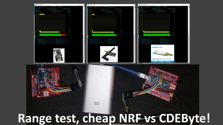
I received 2 new CDEByte antennas that needed a range test. As I live in a mansion.... Next to a park we figured out that walking 1 degrees outside would be an excellent time to do a range test. It was not raining so.....
Our conclusion would be:
- Cheap ass NRF... good enough for indoor usage.. if it can mesh.
- Cheap ass Amplified NRF.. good enough in the house, needs a bit more space and power, but works quite well.
- CDEByte... not cheap.. but man my hands were freezing outside due to the long range.. And according to @Yveaux we could achieve a higher range if we would have set the power to MAX... During testing this was MIN.
 link url))
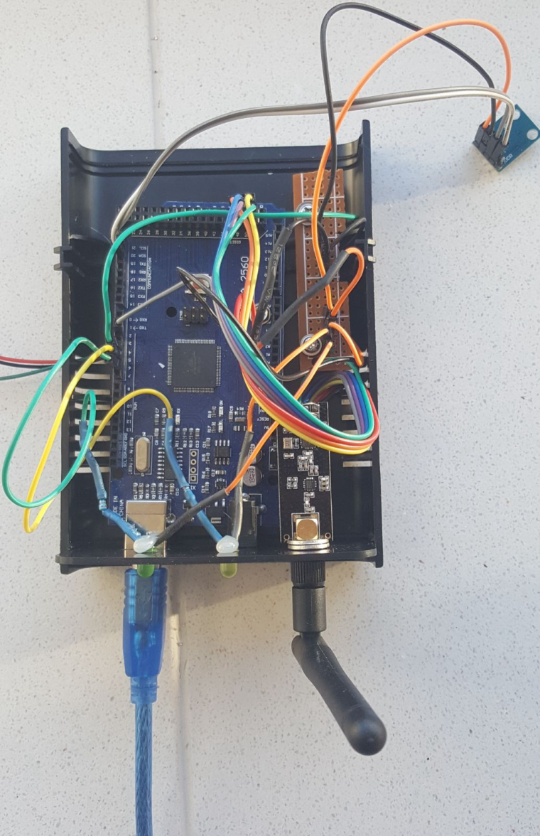
 .
.