Navigation

    • Register
    • Login
    • Search
    • OpenHardware.io
    • Categories
    • Recent
    • Tags
    • Popular
    1. Home
    2. sincze
    3. Posts
    • Profile
    • Following
    • Followers
    • Topics
    • Posts
    • Best
    • Groups

    Posts made by sincze

    • RE: Smartmeter sensors

      Sorry to bump this all thread back to 2018, but I have a question.
      Is it already possible to use MySensors and this all in one P1 domoticz sensor? (usage1,2 / return1,2)

      The examples I can find create 2-4 new sensors in Domoticz. I'm looking forward to the possibilitie if it can be done with one πŸ˜‰

      0_1528314100556_All in one p1.JPG

      It can be done with a P1 http request but as a MySenors user I want to do it with mysensors.

      The idea is to use this PCB as P1 and Watermeter πŸ˜‰
      0_1528314499956_Wemos Smar Water meter.jpg

      posted in My Project
      sincze
      sincze
    • RE: What did you build today (Pictures) ?

      @tbowmo interesting indeed, tnx for sharing. Currently I still use Domoticz for the API Logging is done with INFLUX and Grafana. However in addition to Domoticz I use Pass2PHP. I can now control everything with PHP. PHP seems pretty common so a lot of examples I can find online ;-0. I am a complete MQTT / NODE-RED NOOB.

      posted in General Discussion
      sincze
      sincze
    • RE: ARDUINO+WIFI -> Domoticz on Raspberry Pi3 (water meter)

      @marsault6 If you are going to use an ESP8266 (like nodeMCU) you can configure it as an actual mysensors gateway + Node. The Node would be your watermeter. πŸ˜‰

      posted in General Discussion
      sincze
      sincze
    • RE: Wireless Peacefair PZEM-004T Energy Monitor on Audrino Web Server

      I received my unit today. Let's see if we can make the baby talk MySensors.

      0_1516470233698_WhatsApp Image 2018-01-20 at 18.36.11.jpeg

      posted in My Project
      sincze
      sincze
    • RE: What did you build today (Pictures) ?

      Finally, the last day of my holiday I managed to upload the Mysensors Sketch into the NodeMCU to control my 900 LEDS. It will also read the lux intensity in the livingroom. So if it is dark the lights will switch on.

      0_1515346564306_NodeMCU Driving LED.jpg

      All is based on @Yveaux Mysensors ESP Gateway port. On a rainy saterday last year @Yveaux and I found out we did not have to modify anything on the voltag level for driving the LEDS. πŸ˜‰

      The sketch includes all the Doll_House animations (around 55) that can be skipped through using an old 433mhz remote (or via interface directly ofcourse) Next stop... Installing 15 meters of LED in the livingroom. pffff πŸ˜‰

      And putting everything inside this little box @Yveaux printed for me.
      0_1515346955766_Box.jpeg

      posted in General Discussion
      sincze
      sincze
    • RE: Combining MySensors examples

      @kimot said in Combining MySensors examples:

      MockMySensors

      Haha tnx glad I learned something today. Did not know about this example πŸ˜‰

      posted in Development
      sincze
      sincze
    • RE: Combining MySensors examples

      @bluezr1 I can imagine your struggle. Have had my fair share as well. The following code is running stable and has around 9 sensors it is serving. Maybe you can grab the pieces you need for your nodes. Unfortunately did not make a video.

      posted in Development
      sincze
      sincze
    • RE: What did you build today (Pictures) ?

      @andrew said in What did you build today (Pictures) ?:

      AndrΓ‘s Kabai

      Nice video AndrΓ‘s πŸ˜‰

      posted in General Discussion
      sincze
      sincze
    • RE: Renovent HR Medium/Large - Brink Climate Systems

      Just an update regarding the Renovent Climate system:
      I created the following cheat sheet:

      0_1515262533789_Renovent Cheat Sheet.jpeg

      To be able to read the 'filter' value I converted the default RJ11 to RJ12.
      Now it should be able to warn me that I need to change the filter.
      0_1515262827287_Brinks Filter.jpeg

      As I use the EasyPCB and already used all available pins on the prototype board, I had to solder an extra wire to pin 8.
      Q: How do I access A2, A3 and D8? A: They are not accesses through the PCB, so you need to directly solder to the pro mini.

      As this Pin 8 is not used with pull up resistor (I thought it was dangerous to do that because adding 3v of the Renovent would kill the input.) I needed to build some sort of pull-down resistor from keeping the input pin from floating. And hell yes it was floating like hell (resulting in a lot of messages, that even the debouncer was unable to deal with).

      Normally when the filter is 'clean' there is a 0v on P8. If the filter needs to be cleaned there is a +/- 3v on P8

      This how it was solved:
      0_1515266087589_Pull-Down.JPG

      posted in My Project
      sincze
      sincze
    • RE: What did you build today (Pictures) ?

      I found out that the brinks solution I build some time ago could be upgraded with a nice additional feature. 'Filter detection'.

      I created a cheat sheet as my device was equiped with RJ11 connector and 3 wires. I needed to convert it to RJ12 with filter detection.

      0_1514922290404_WhatsApp Image 2018-01-02 at 20.40.46.jpeg

      A nice black conversion box Output wires are the same colour as the original RJ 1 wire. With 2 extra wires 3,3v or 5v for the digital 'one' on the arduino.

      0_1514922284342_WhatsApp Image 2018-01-02 at 20.38.14.jpeg

      posted in General Discussion
      sincze
      sincze
    • RE: Beginner - what is wrong

      Mmm i think I received a DOA... No pling pling sound in windows...

      posted in OpenHAB
      sincze
      sincze
    • RE: What did you build today (Pictures) ?

      @dbemowsk You are correct πŸ˜‰ , well at least I thought I bought those but got: SK6812 RGBW (comparable to ws2812b). The pretty work just fine.

      posted in General Discussion
      sincze
      sincze
    • RE: What did you build today (Pictures) ?

      @dbemowsk Well first I started with my all time favourite... the Nano, as I have prototyping boards available.;-) but even with some simple light shows it did not have enough memory to hold de states of each individual 900 LEDs.

      I moved to the Mega. as it has more memory. My sketch worked fine so I started to build the node in its box. I also looked at the Github for the Doll House inspiration. I found the library that had 56 effects. So I thought why not use that one... Migrated my sketch, did a few tests with 300 LEDS, completed the enclosure and only than found out It could not controll all the 900 leds, due to memory issue. Insufficient RAM.

      But as this forum is a learning curve for me please feel free to share your thoughts. I always look at examples from others and see what I can do with it myself. I don't have fancy PCB equipment, justs a soldering iron and my own Aliexpress wearhouse with components πŸ˜‰

      posted in General Discussion
      sincze
      sincze
    • RE: What did you build today (Pictures) ?

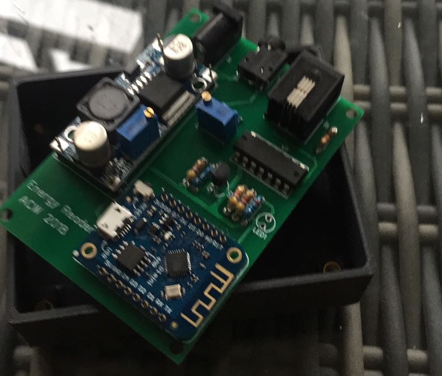
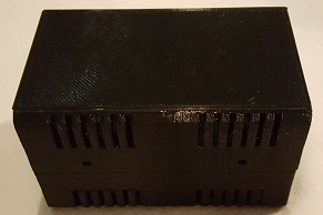
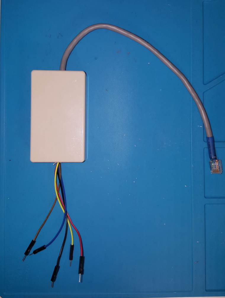
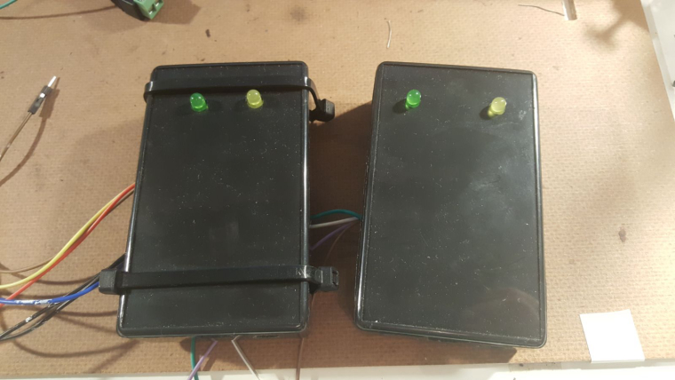
      Well as you can see, my prototyping skills are not at the level of @dbemowsk (always interested in the under side of the boards, mine look .. yeah a mess?), however I managed to create this enclosure (once closed looks nice enough).

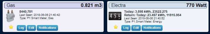
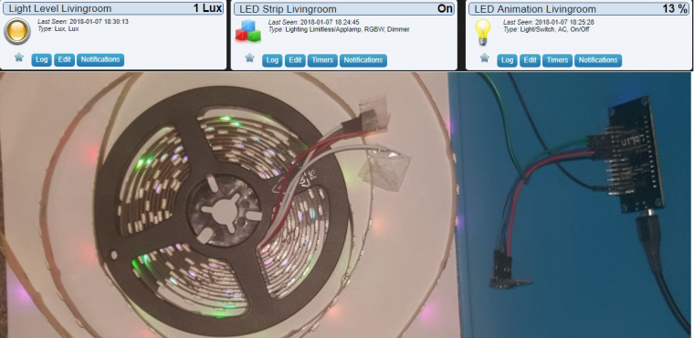
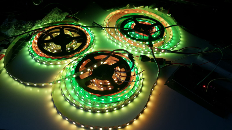
      It should control the programmable LED lights in my livingroom (900 pieces).The board is powered 5v from the same power supply as the LED's. In addition it needs to measure the lux in the livingroom to decide if it is dark enough to turn on the lights.

      0_1513502717712_LED Controller.jpeg

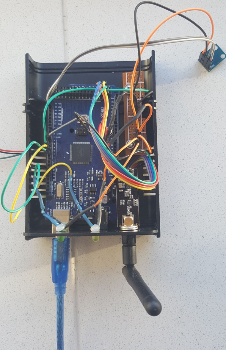
      Initial tests looked okay, however after finding 56 effects in the Doll House of @Yveaux I decided to use that FX library as well. However the Arduino Mega is out of RAM to accomodate a full controll of the 900 LEDS. It will only control around 650 LEDS with that FX library.

      After being in contact with @Yveaux we decided to use an ESP solution. I have a spare NodeMCU v3 that can house the ESP gateway sketch and will have enough memory to controll the LEDs. Well now I have to look for a nice prototyping thing/case for the NodeMCU and add a level shifter as well. The LED's control line wants to be controlled by at least 3,7v.

      This is the nice thing about these kind of projects.. "There is always something to do"

      posted in General Discussion
      sincze
      sincze
    • RE: Combining relay and temperature sketch

      haha combining sketches... frees up some hardware πŸ˜‰ for other stuff.

      0_1512839095158_WhatsApp Image 2017-12-09 at 18.04.14.jpeg

      posted in Troubleshooting
      sincze
      sincze
    • RE: What did you build today (Pictures) ?

      Almost Christmas, that means... Lights. In this case programmable 5v LED's that are driven by an Arduino and controlled via Mysensors & Domoticz.

      0_1512836207823_WhatsApp Image 2017-12-09 at 17.14.55.jpeg

      While the arduino sketch has a lot of tricks (showing animations).. I still have to figure out HOW I can stop an animation from playing when I want to see the next one.. It now completes the first animation.. and then starts the one I selected. It needs to break from the function if a new message comes in. I'll have to look for some examples in the forum.

      posted in General Discussion
      sincze
      sincze
    • RE: What did you build today (Pictures) ?

      @andrew Wow indeed.

      posted in General Discussion
      sincze
      sincze
    • RE: What did you build today (Pictures) ?

      @rmtucker ai ai . what happened with the salt???

      posted in General Discussion
      sincze
      sincze
    • RE: What did you build today (Pictures) ?

      @manutremo As the water indeed is 'rock' solid here in the area I was pretty succesfull using the digital pins. A short... when there is a water connection or open... when there is no connection. No false alarms. Only legit... Each leakage costs me money to get some guy to fix it for me. But at least the floor is not ruined anymore as I had that the first 2 times.

      posted in General Discussion
      sincze
      sincze
    • RE: What did you build today (Pictures) ?

      @neverdie Great tip, this will resolve in even a quicker response during a flood right?. I already added toilet paper as cover for a smooth moist/water distribution. Lets add some salt to that and hopefully never see an error message again. But I wont bet a bitcoin on that ;-).. Happy with this cheap solution.

      posted in General Discussion
      sincze
      sincze
    • RE: Combining relay and temperature sketch

      @rejoe2 NIce example thanks.

      posted in Troubleshooting
      sincze
      sincze
    • RE: What did you build today (Pictures) ?

      And so it it almost Christmas...

      Jolly jolly.. wel actually no....

      We have had wet feet from the central heating system serveral times now around Christmas or New Year.
      Causing a wet floor and other possible disasters. Yes I know.. A Central Heating Mechanism should not leak, you could try putting a bucket underneath... But that is not 'that home automation' smart that I was looking for.

      So to detect a leakage.... I came up with this some time ago.

      Pretty standard, a few wires... a Mysensors Node... and Pushover to send me urgens notifications about the leakge.

      0_1512750844649_Leakage.jpg link url))

      And ladies and gentlemen it actually works as you can see in the pushover sreenshot, it kicked off today.

      posted in General Discussion
      sincze
      sincze
    • RE: What did you build today (Pictures) ?

      This sunday a friend of mine and I did not know what to build. So we decided to use a project designed by @Yveaux
      Source

      I received 2 new CDEByte antennas that needed a range test. As I live in a mansion.... Next to a park we figured out that walking 1 degrees outside would be an excellent time to do a range test. It was not raining so.....

      Our conclusion would be:

      • Cheap ass NRF... good enough for indoor usage.. if it can mesh.
      • Cheap ass Amplified NRF.. good enough in the house, needs a bit more space and power, but works quite well.
      • CDEByte... not cheap.. but man my hands were freezing outside due to the long range.. And according to @Yveaux we could achieve a higher range if we would have set the power to MAX... During testing this was MIN.

      0_1512323585357_cdebytetest.jpg

      posted in General Discussion
      sincze
      sincze
    • RE: What did you build today (Pictures) ?

      @dakipro we use kodi on al lgl tvs. The libreelec TV box has cec and can turn on the TV via hdmi. If TV is on I am able to control the volume via the LG webserver. Kodi (api) can display the notifications for Me :). Not that fancy but it works like a charm.

      posted in General Discussion
      sincze
      sincze
    • RE: What did you build today (Pictures) ?

      @dbemowsk while you are at it..consider πŸ™‚

      The dishwasher can be added as well. My devices dishwasher / washing machine / dryer send messages to all tvs that are turned on. Identifying themselves and invite you to come and clean them :). It comes in handy and absolutely jaw dropping on your visitors.

      If you turn on the stove air circulation system in the kitchen... Why not greet the wife with automatically start the TV in the kitchen and play her favourite radio channel at her preferred volume...

      posted in General Discussion
      sincze
      sincze
    • RE: Easy/Newbie PCB for MySensors

      @zboblamont @gohan The Sensor with the replaced Pro Mini is in production now ;-). I'll start soldering a new Easy/Newbie PCB, because once you know how to do it... it is Easy and test the individual pins with a door/window sensor.

      posted in Hardware
      sincze
      sincze
    • RE: Easy/Newbie PCB for MySensors

      @gohan Don't know. Pin3 could be used to drive the led tx without problems. It only did not work with the temp sensors. I moved the temp sensor to d2.... modified the sketch and it did not work as well. and d2 was driveing rx led. So well root cause unknown... solution: solder a new pro mini and keep the other one for different purpose.

      posted in Hardware
      sincze
      sincze
    • RE: What did you build today (Pictures) ?

      0_1510959314040_Dallas Working.jpg
      With help of @dbemowsk @sundberg84 I was able to complete my "CV All in one sensor" using the easy PCB. πŸ˜‰
      It now replaces 2 Arduino Nanos with only 1 Easy PCB. Currently the 0,1u Capacitor is missing, however as I was told by the designer it still could work. And it does.

      This node:

      • monitors the pipes of my central house heating,
      • Is able to detect if the heating unit has a leakage.
      • Switches on the light if the door is opened
      • if the humidity in the bathroom becomes to high, or somebody is cooking.. It will start the BRINKS central WTW.
      • Can reset my OTGW unit if it has a lock up.

      0_1510959911977_Vloerverwarmin.JPG

      posted in General Discussion
      sincze
      sincze
    • RE: Easy/Newbie PCB for MySensors

      @sundberg84 I just soldered a myself a new out of the box pro mini using the same sketch..

      10246 TSF:MSG:SEND,8-8-25-0,s=0,c=1,t=0,pt=7,l=5,sg=0,ft=4,st=OK:21.0
      250560 TSF:MSG:SEND,8-8-25-0,s=0,c=1,t=0,pt=7,l=5,sg=0,ft=0,st=OK:21.1
      255019 TSF:MSG:SEND,8-8-25-0,s=0,c=1,t=0,pt=7,l=5,sg=0,ft=0,st=OK:22.3
      259476 TSF:MSG:SEND,8-8-25-0,s=0,c=1,t=0,pt=7,l=5,sg=0,ft=0,st=OK:23.8
      263934 TSF:MSG:SEND,8-8-25-0,s=0,c=1,t=0,pt=7,l=5,sg=0,ft=0,st=OK:25.3
      268393 TSF:MSG:SEND,8-8-25-0,s=0,c=1,t=0,pt=7,l=5,sg=0,ft=0,st=OK:26.5
      272851 TSF:MSG:SEND,8-8-25-0,s=0,c=1,t=0,pt=7,l=5,sg=0,ft=0,st=OK:27.6
      277310 TSF:MSG:SEND,8-8-25-0,s=0,c=1,t=0,pt=7,l=5,sg=0,ft=0,st=OK:28.1
      281768 TSF:MSG:SEND,8-8-25-0,s=0,c=1,t=0,pt=7,l=5,sg=0,ft=0,st=OK:28.4
      290677 TSF:MSG:SEND,8-8-25-0,s=0,c=1,t=0,pt=7,l=5,sg=0,ft=0,st=OK:28.3
      295136 TSF:MSG:SEND,8-8-25-0,s=0,c=1,t=0,pt=7,l=5,sg=0,ft=0,st=OK:28.1
      299594 TSF:MSG:SEND,8-8-25-0,s=0,c=1,t=0,pt=7,l=5,sg=0,ft=0,st=OK:27.8
      304053 TSF:MSG:SEND,8-8-25-0,s=0,c=1,t=0,pt=7,l=5,sg=0,ft=0,st=OK:27.6
      308511 TSF:MSG:SEND,8-8-25-0,s=0,c=1,t=0,pt=7,l=5,sg=0,ft=0,st=OK:27.3
      312970 TSF:MSG:SEND,8-8-25-0,s=0,c=1,t=0,pt=7,l=5,sg=0,ft=0,st=OK:27.1
      317428 TSF:MSG:SEND,8-8-25-0,s=0,c=1,t=0,pt=7,l=5,sg=0,ft=0,st=OK:26.8
      321887 TSF:MSG:SEND,8-8-25-0,s=0,c=1,t=0,pt=7,l=5,sg=0,ft=0,st=OK:26.6
      326345 TSF:MSG:SEND,8-8-25-0,s=0,c=1,t=0,pt=7,l=5,sg=0,ft=0,st=OK:26.4

      Victory... πŸ™‚

      posted in Hardware
      sincze
      sincze
    • RE: Easy/Newbie PCB for MySensors

      @sundberg84 haha yes i was wondering that myself so tried it connecting it to 3,3v as well. However on the 5v nano working just fine. Technical specs tell me: Power supply range is 3.0V to 5.5V
      also mysensors link
      Pretty strange huh.

      posted in Hardware
      sincze
      sincze
    • RE: Easy/Newbie PCB for MySensors

      @dbemowsk I had those thoughts as well.
      0_1510946155798_Dallas Voltage.png
      The voltage should be okay. I can solder a new Arduino Pro Mini and see if that one wants to work with me πŸ˜‰

      posted in Hardware
      sincze
      sincze
    • RE: Easy/Newbie PCB for MySensors

      @sundberg84 @dbemowsk Thank you guys for still trying to help me. I almost gave up on using a Dallas Termp sensor o n a pro mini. As said I even tried connecting the temp sensor directly to the pins with same results. If I connect the pins to my nano, it is being detected and transmitting temp values. I even used a different sketch.. Just for the temp sensor. link found_here. Changed it to use Pin 3 ofcourse. I even connected the whole thing to D2 (resistor back in the wires)... without being succesful either.

      0_1510938558966_Dallas Not Detected.png

      posted in Hardware
      sincze
      sincze
    • RE: Easy/Newbie PCB for MySensors

      @sundberg84 yes, I have a 'beep' pffffff would a double resistor hurt ?? 1 on pcb the other one in the cable?
      I tried connecting it directly to pin 3 on the arduino, no detection, I tried replacing the resistor. nothing. I tried a different temp sensors.. No detection. I moved the new temp sensor to the nano... detected.
      I tried an empty Dallas temp only sketch on the mini... no detection. Well Now I'm lost πŸ˜‰

      posted in Hardware
      sincze
      sincze
    • RE: Easy/Newbie PCB for MySensors

      @sundberg84 Just for the check A0 or D3 (temp sensor)?
      As A0 is working, I have a relais attached to it. πŸ˜‰

      posted in Hardware
      sincze
      sincze
    • RE: Easy/Newbie PCB for MySensors

      @sundberg84 Strange thing is.. If I unplug the temp cable from the PCB and plug it into the NANO the sketch detects the sensor. The exact same sketch on the mini says "0 sensors found" as I just print the number of sensors detected.
      For debugging purposes If I would solder the resistor on the PCB and I have a different temp sensor with resistor within the cabling. Would that hurt (double resistors) ?
      Would I have to look for a specific voltage between D3 and GND ?

      posted in Hardware
      sincze
      sincze
    • RE: Easy/Newbie PCB for MySensors

      @sundberg84 Got it. In the end it I did not have to use them.

      All devices I was looking for to use are working except for my Dallas Temp Sensors.
      The resistor is between the wires VCC and DATA in the connectors so not soldered on the board itself.

      I checked if pin header
      D3 had connection with D3 on the arduino (beep),
      GND with GND on the arduino (beep),
      VCC with VCC on the arduino (beep) at 4,7v.

      So the connector should be okay (no soldering error this time). If I connect the wire to the old Arduino nano the temp sensors are found... Connect them to the PCB.. Nothing found. Well must be something stupid I am missing here right?.

      To check D3, I made an RX tranmission Led attached and it flashed fine. So it should be okay.

      posted in Hardware
      sincze
      sincze
    • RE: Easy/Newbie PCB for MySensors

      @sundberg84 tnx.
      I looked at the FAQ and could not find an explaination how to use the pins TX/RX.

      The following is now on my build list, but maybe if I can use TX/RX pins it will free something...

      1. LED RX=A05
      2. LED TX=D02
      3. Relay_1=A00
      4. Relay_2=A01
      5. Relay_3=A04
      6. Temp_D03 (total of 4, resistor currently already soldered into the wire)
      7. Door_Switch=D05
      8. Leakage_Switch=D06

      I tested the sketch on a Arduino Nano and it is working, now I need to convert everything to the Easy/Newbie PCB. πŸ˜‰

      posted in Hardware
      sincze
      sincze
    • RE: Easy/Newbie PCB for MySensors

      @sundberg84 as I am not a soldering king... we will check the work and report back...... applied a bit more solder to the vout and we have beep πŸ˜‰ now let's continue the work.
      Wow, 3,3 and 3,29v on the antenna. tnx.

      posted in Hardware
      sincze
      sincze
    • RE: Easy/Newbie PCB for MySensors

      @sundberg84 unfortunately yes. However.

      You can do a continuity test from Vout to VCC (radio) , (We have no beep for continuity)
      and
      GND(radio) to GND(screw terminal) to comfirm connectiom. (We have a beep for contiuity)

      posted in Hardware
      sincze
      sincze
    • RE: Easy/Newbie PCB for MySensors

      @sundberg84 I did measure the following:

      plus (left pin) on blue screw terminal (should be 5v), is 4,96 V
      Vin voltage reg (should be 5v), is 4,96
      Vout Voltage reg (should be 3.3v), is 3,3

      posted in Hardware
      sincze
      sincze
    • RE: Easy/Newbie PCB for MySensors

      So this is where the project is at. Using regulated 5V.
      Still missing the 0,1u capacitor, but it is on its way,
      0_1510686541052_PCB_001.jpg

      The voltage divider is working fine 5v -> 3,3v.
      Maybe I am missing some(connection)thing as I don't have 3,3v at the Antenna 3,3/GND connector. Did I miss something as I am not a PCB expert, sorry.

      posted in Hardware
      sincze
      sincze
    • RE: Issues between Wifi (router) and NRF24L01

      @Yveaux Nice enclosure πŸ˜‰ I don't dare to show my box. Always interested in visuals of the inside of this stock box of yours. Just for some old Chinese copy paste work πŸ˜‰

      posted in Hardware
      sincze
      sincze
    • RE: What did you build today (Pictures) ?

      @mfalkvidd ai ai. Yes. I was warned on the Domoticz website about the 'not being able to startup'. I was able to successfully update from Wheezy to Jessi. Skipped the Stretch part for now.

      Just made some preparations for the new node that has to replace several individual nodes in the technical-room. (Control of WTW, Measurement of heating pipes of CV using Temperature Sensors, Leakage Detector of CV, Door Sensor and last but not least OTGW-Reset)
      0_1510504350773_What_i_did_today-resized.jpg

      Could not complete the PCB due to some missing components. The Sketch is running fine on my NANO
      0_1510504673338_Proto-resized.jpg
      Looks like a mess now, but this development PCB comes in quite handy.

      posted in General Discussion
      sincze
      sincze
    • RE: πŸ’¬ Easy/Newbie PCB for MySensors

      Damn. Just missing the 0,1uF capacitor ..... to complete the 5v build. This will be my smallest build yet πŸ˜‰ using PCB v9

      posted in OpenHardware.io
      sincze
      sincze
    • RE: Easy/Newbie PCB for MySensors

      @dbemowsk Got in stock 2 types of LM1117 the 3,3v and 5v. In any case the relais need 5v, the temp sensor as well. So If I read RAW in your answer that triggers me to watch out. πŸ˜‰ I'll start soldering some pins and measure the voltage. as @sundberg84 said.. "all you can do is test and learn !! hehehe. Part of the Mysensors fun. And ofcourse this forum provides me with experienced feedback.

      posted in Hardware
      sincze
      sincze
    • RE: Easy/Newbie PCB for MySensors

      @sundberg84 Ok tnx for the heads up. Currently I have everything in DEMO up and running on a NANO on my desk (using the exact same pins as I would on your PCB.
      I was thinking of the following. Power the PCB with 5v and use a 5v arduino mini, use the LE33 to power the Antenna with 3,3v. Hopefully this will enable the pins Mys pins A0 ...Dx with 5v.(Have to look at the schematic to be sure). Keeping your advise in mind to add some extra juice I have to power the RELAIS & Temp sensor separately with 5v and keep the grounds of everything together with the PCB. I think it should work. But maybe I am missing something.

      posted in Hardware
      sincze
      sincze
    • RE: Easy/Newbie PCB for MySensors

      @dbemowsk said in Easy/Newbie PCB for MySensors:

      LDO regulator

      A well that is a clear answer. So I just ordered a few LE33. The project has to wait.
      It still will be a tough one getting everyting attached to the pins. ->. 2x Door Sensor / 3x Dallas DS18B20 / 3x Relais / 2x Control LEDS TX/RX. A well part of the game. Already figured out I have to use the A0x pins as digital ones. As i don't plan to use IRQ I'm really hopeful this nicely designed PCB will offer me A0,A1A4,A5 D2,D3,D5,D6. So should fit πŸ˜‰

      posted in Hardware
      sincze
      sincze
    • RE: Easy/Newbie PCB for MySensors

      @sundberg84: Received the V9 boards and started to work with them. Converting my nodes into smaller ones πŸ˜‰

      I want to use it with my 5v arduino. So need voltage regulator for the radio. I guess you are using LE33 if I read the thread correctly. I have LM1117 which seems to be a hassle to fix on the board with the 'rough bulky' legs. Suggestions or just buy LE33 πŸ˜‰

      posted in Hardware
      sincze
      sincze
    • RE: Car Aux Battery Monitor

      @Boots33 Nice application. Inspired me to have a look at the charge / discharge of my motorcycle battery. πŸ˜‰

      posted in My Project
      sincze
      sincze
    • RE: πŸ’¬ MySensors @Eindhoven Maker Fair 2017 2-3 September

      @GertSanders No worries. We talked about your automated chicken Shed and flood control in a basement via GSM node to some other nice Belgium guy. πŸ˜‰ that was looking for a flood control solution. So you were mentioned.

      posted in Announcements
      sincze
      sincze
    • RE: Are folks here happy with Domoticz?

      @rmtucker I move the data directly from Domoticz into influxDB. This is as accurate as you will get it πŸ˜‰ Data for example of my smartmeter every 10 seconds. If the device is updated in Domoticz (energy sensor for example) this will add data to influxDB and you will get the bet graphs. Accurate for me.

      posted in Domoticz
      sincze
      sincze
    • RE: Are folks here happy with Domoticz?

      In the beginning I worked with DomotiGa on a raspberry. However due to all the crashes of my SD card and the long restore time (rebuilding / recompiling of DomotiGa) I had a shadow system on a separate Raspberry with Domoticz to figure out how it worked. In the end I also moved Domoticz from SD to an SSD using a Cubietruck backend. To speed Domoticz a little bit more I moved away from the standard (integrated) scripts and lua to Pass2PHP. Now all automatic controls are dealt with by PHP while still being able to use all de 'hardware' features and interface of domoticz itself. . As a result I have a fast responding system that integrates with all my domotica hardware flawless. The community is really big. And yes. Sometimes you run into a bug. But I assume that can happen anywhere.

      posted in Domoticz
      sincze
      sincze
    • RE: Renovent HR Medium/Large - Brink Climate Systems

      @sincze https://github.com/sincze/mysensors_brinks_renovent (seems the link in the post did not work)

      posted in My Project
      sincze
      sincze
    • Renovent HR Medium/Large - Brink Climate Systems

      I wanted to have my Renovent HR Large from Brink Climate Systems automated.
      Unfortunately Brink offered a € 300 solution to do this wireless within the house

      I thought.. Well it must be possible to use one of the Mysensors sketches to do so.

      By default this system comes with a 3 way switch that is connected to an rj11 plug on the Renovent.
      The RJ11 has 3 cables

      • Yellow
      • Red
      • Black

      After figuring out how the 3 way switched worked it was an easy task with one of the example sketches.

      • Yellow + Black = Switch_2
      • Red + Black = Switch_3
      • By default nothing is connected = Switch_1.

      If you would like to measure voltage you will measure aroun 13,88v on

      • yellow-black
      • red-black.

      The sketch can be found here:
      0_1500406156812_sketch_jul16a_-_Brinks_WTW.ino

      You will need 2 Relais if you want to switch Switch_2 and Switch_3.
      Please see attached the prototype... available for around €10 .
      0_1500406337706_WTW Brink - Prototype.JPG

      And then within Domoticz I can control it.
      0_1500406123667_WTW Brink.JPG
      If the humidity in the bathroom is over 58% kick on the fan πŸ˜‰

      Oh btw. don't forget to connect the ground of the Relais to the Ground of the Arduino, otherwise it will not work.

      Happy Mysensors day.

      sincze.

      posted in My Project
      sincze
      sincze
    • Monitor Alarm System state (Jablotron)

      I've read a lot of posts here and wanted to monitor the state of my ALARM system in Domoticz (not control it).

      With all your posts and input from @yveaux I combined it to the following.
      0_1486401836126_OASIS.png

      2 buck converters, an arduino and some wiring.

      The alarm will set 12v on PGY / PGX connectors if set and 0v if unset.

      We only need to convert that 12v into an acceptable input voltage for ARDUINO digital in.
      I used the buck converter for this purpose, 4,45v is sufficient to trigger digital 1.
      and the 0v ... digital 0.
      Don't use the internal pull up resistor of this pin πŸ˜‰

      I tried powering the Arduino from the alarm as well with the separate buck converter... however that was nu success. Could not figure out why. Pins became unresponsive.

      The arduino is now powered by separate power supply from the ISP modem...

      And the final result:
      1_1486402114270_OASIS-set.jpg

      0_1486402114270_OASIS-domoticz.jpg.

      I will post the code on my github. So everybody can have a look at it if they want.
      https://github.com/sincze/jablotron_Mysensors_2.0.1

      In addition I also added a doorsensor. Should somebody open the door I'm also notified.

      And all thanks to MySensors.

      posted in My Project
      sincze
      sincze
    • RE: LM393 Light Sensor Readings

      @mfalkvidd , Indeed 0 - 100 not in lux as shown in Domoticz. That is why I started on a lux meter. Just to see how that works. With LM393 I just check... if value < 10 ... it must be dark enough to switch on the lights.

      Works ideally when it is very dark during the day when a thunderstorm moves over your house.

      posted in Troubleshooting
      sincze
      sincze
    • RE: Chinese rubbish.... or is it?

      @Yveaux : At least you were able to figure it out. I would simply have connected the thing and start sending smoke signals.

      posted in Hardware
      sincze
      sincze
    • RE: Smartmeter sensors

      @Japio can you share your modification with the timers??

      Funny thing as I have solar panels.
      Today I had -1450 Watt on my Smartmeter and the script shows this as 1450 Watt in Domoticz (so positive) 🍭 Have to look into that this weekend. Maybe I need glasses πŸ˜‰

      Don't worry if your version is Mysensors < 2.0.0. I will convert it as I need the 2.0.0+ version anyway.

      posted in My Project
      sincze
      sincze
    • RE: Smartmeter sensors

      @hek haha you are fast!.

      I would say @GertSanders I read these articles and was convinced altsoftserial it was for the nano.

      https://hackaday.io/project/95-altsoftserial-arduino-library
      http://forum.arduino.cc/index.php?topic=152122.0
      https://www.arduino.cc/en/Reference/SoftwareSerial
      http://hackaday.com/2012/02/13/altsoftserial-looks-to-speed-up-arduino-software-uart/

      posted in My Project
      sincze
      sincze
    • RE: Smartmeter sensors

      @Japio tnx for the inspiration and first version of the program.
      I just had to have this working in my 2.0.0+ Mysensors πŸ˜‰ and modified it a bit.

      Added some TX/RX/ERR leds and had to move some pins.
      In addtition I apply permanent 5v to receive data packages so removed some things from the initial program.

      /////////////////////////////////////////////////////////////////////////////////////
      // Name: MySensors node for Kamstrup smartmeter
      // Version: 1.0
      // Date: Aug 1, 2016
      // Author: Jaap van Alphen
      // Description:
      // Exposes the following sensors:
      // Id   Name                              Additional info
      //  1   +T1                               Updated every hour
      //  2   +T2                               Updated every hour
      //  3   -T1                               Updated every hour
      //  4   -T2                               Updated every hour
      //  5   Tariff                            Updated on change of tariff
      //  6   Current usage electricity         Updated every 10 seconds
      //  7   Current production electricity    Updated every 10 seconds
      //  8   Switch state                      Updated on each change of switch state
      //  9   Gas reading                       Updated when time stamp changes (every hour)
      //  10  Gas time stamp                    Time stamp of last gas reading
      //
      // This software comes as-is, you may alter this source code to your wish, but author is in no circumstance 
      // responsible for any damage you make to your smart meter, or any other hardware.
      //
      // Version: 1.1
      // Date: Oct 4th, 2016
      // Author: Jaap van Alphen
      // Modified: Sandor Incze / Michel Schilthuizen
      //
      // Based on the tips: http://gejanssen.com/howto/Slimme-meter-uitlezen/
      // RJ11 Pin layout:   pin 1 request (RTS)   - ARDUINO 5V
      //                    pin 2 GND             - ARDUINO GND
      //                    pin 3 N.C
      //                    pin 4 RxD             - ARDUINO NANO D08
      //
      // AltSoftSerial always uses these pins:
      //
      // Board          Transmit  Receive   PWM Unusable
      // -----          --------  -------   ------------
      // Teensy 2.0         9        10       (none)
      // Teensy++ 2.0      25         4       26, 27
      // Arduino Uno        9         8         10
      // Arduino Mega      46        48       44, 45
      // Wiring-S           5         6          4
      // Sanguino          13        14         12
      
      // D8         Serial input from smartmeter (default port for AltSoftSerial). 
      //            Note that meter output sometimes needs to be inverted.
      //            http://domoticx.com/p1-poort-slimme-meter-uitlezen-hardware/
      /////////////////////////////////////////////////////////////////////////////////////// 
      
      // ADD Some LEDS if you want to monitor Mysensors traffic
      
      /*
       * Wire connections (OPTIONAL):
       * - Inclusion button should be connected between digital pin 3 and GND  
       * - RX/TX/ERR leds need to be connected between +5V (anode) and digital pin 6/5/4 with resistor 270-330R in a series
       *
       * LEDs (OPTIONAL):
       * - To use the feature, uncomment MY_LEDS_BLINKING_FEATURE in MyConfig.h
       * - RX (green) - blink fast on radio message recieved. In inclusion mode will blink fast only on presentation recieved
       * - TX (yellow) - blink fast on radio message transmitted. In inclusion mode will blink slowly
       * - ERR (red) - fast blink on error during transmission error or recieve crc error 
       */
      
      // Enable debug prints to serial monitor
      #define MY_DEBUG 
      #define MY_NODE_ID 20
      
      // Differten PIN to keep Altserial Working ;-) and NANO Happy
      
      #define MY_RF24_CE_PIN 3
      #define MY_RF24_CS_PIN 7 
      
      // Enable and select radio type attached
      #define MY_RADIO_NRF24
      //#define MY_RADIO_RFM69
      
      // Set LOW transmit power level as default, if you have an amplified NRF-module and
      // power your radio separately with a good regulator you can turn up PA level. 
      #define MY_RF24_PA_LEVEL RF24_PA_LOW
      
      // Enabled repeater feature for this node
      // #define MY_REPEATER_FEATURE
      
      // Flash leds on rx/tx/err
      // enable #define MY_LEDS_BLINKING_FEATURE finction in MyConfig.h
      #define MY_LEDS_BLINKING_FEATURE
      // Set blinking period
      #define MY_DEFAULT_LED_BLINK_PERIOD 300
      
      // Inverses the behavior of leds
      //#define MY_WITH_LEDS_BLINKING_INVERSE
      
      #define MY_DEFAULT_ERR_LED_PIN 4  // Error led pin  RED LED
      #define MY_DEFAULT_RX_LED_PIN  6  // Receive led pin  GREEN LED
      #define MY_DEFAULT_TX_LED_PIN  5  // the PCB, on board YELLOW LED
      
      #include <SPI.h>
      #include <MySensors.h>
      #include <AltSoftSerial.h>
      
      //#define NO_RADIO                      (1)       // Define this symbol when no radio is connected
      #define EMETER_TIMEOUT                (600000) // Time between sending the electric meter standings
      
      //  SensorDefinitions
      // #define NODE_ID                       (20)  // Node ID for the Smartmeter node
      #define SENSOR_ID_PLUS_T1             (1)   // Sensor ID for Electric meter, Plus T1
      #define SENSOR_ID_PLUS_T2             (2)   // Sensor ID for Electric meter, Plus T2
      #define SENSOR_ID_MIN_T1              (3)   // Sensor ID for Electric meter, Min T1
      #define SENSOR_ID_MIN_T2              (4)   // Sensor ID for Electric meter, Min T2
      #define SENSOR_ID_CURRENT_TARIFF      (5)   // Sensor ID for Electric Current tariff
      #define SENSOR_ID_CURRENT_USAGE       (6)   // Sensor ID for Electric current usage
      #define SENSOR_ID_CURRENT_PRODUCTION  (7)   // Sensor ID for Electric Electric current production
      #define SENSOR_ID_SWITCH_STATE        (8)   // Sensor ID for Electric meter, switch state
      #define SENSOR_ID_GAS_METER           (9)   // Sensor ID for Gas meter reading
      #define SENSOR_ID_GAS_TIMESTAMP       (10)  // Sensor ID for Gas meter, timestamp of last measurement
      
      #define BUFSIZE 450 // Receive buffer size
      
      
      // Search filters in received data.
      // NOTE: This data remains in Flash!
      const char pT1_Filter[]     PROGMEM ={"1-0:1.8.1("};
      const char pT2_Filter[]     PROGMEM ={"8.2("};
      const char mT1_Filter[]     PROGMEM ={"1-0:2.8.1("};
      const char mT2_Filter[]     PROGMEM ={"1-0:2.8.2("};
      const char cT_Filter[]      PROGMEM ={"0-0:96.14.0("};
      const char cUsageFilter[]   PROGMEM ={"1-0:1.7.0("};
      const char curProdFilter[]  PROGMEM ={"1-0:2.7.0("};
      const char cSwitchSFilter[] PROGMEM ={"0-0:96.3.10("};
      const char cGasMFilter[]    PROGMEM ={"(0-1:24.2.1)(m3)"};
      const char cGasTSFilter[]   PROGMEM ={"0-1:24.3.0("};
      
      AltSoftSerial mySerial;
      
      char buffer[BUFSIZE]; //Buffer for serial data to find.
      
      // Global values
      char          LastGasTimestamp[13];
      int           LastCurTariff=0;
      int           LastSwitchState=0;
      unsigned long lastEMeters=0;
      bool          firstRun=true;
      
      
      // Helper functions
      unsigned long CorrectOverflow(unsigned long newValue, unsigned long compare);
      
      // Gateway send functions
      void SendFloat(int SensorId, int Precision, float Value);
      void SendBool(int SensorId, bool Value);
      void SendString(int SensorId, char* Value);
      
      // Data parse functions
      void ParseCurrentTariff();
      void ParseCurrentUsage();
      void ParseEMeters();
      void ParseGasMeter();
      void ParseSwitchState();
      
      unsigned long CorrectOverflow(unsigned long newValue, unsigned long compare)
      {
        if (newValue < compare)
        {
          return 0;
        }
        else
        {
          return compare;
        }
        
      }
      
      void SendFloat(int SensorId, int Precision, float Value)
      {
        bool bSucceeded = false;
        int ResendCount = 0;
        MyMessage msg(SENSOR_ID_PLUS_T1,V_WATT);
      #ifndef NO_RADIO
        
        while (bSucceeded ==false)
        {
          bSucceeded =  send(msg.setSensor(SensorId).set(Value,Precision));
          if (bSucceeded == false)
          {
            if (ResendCount < 10)
            {
              delay(50);
              ResendCount++;
            }
            else
            {
              bSucceeded = true;
            }
          }
        }
      #endif
        
      }
      
      void SendBool(int SensorId, bool Value)
      {
        bool bSucceeded = false;
        int ResendCount = 0;
        int IntValue=0;
        MyMessage msg(SENSOR_ID_PLUS_T1,V_WATT);
      
      #ifndef NO_RADIO
      
        if (Value == false)
        {
          IntValue = 0;
        }
        else
        {
          IntValue = 1;
        }
      
        while (bSucceeded ==false)
        {
          bSucceeded =  send(msg.setSensor(SensorId).set(IntValue));
          if (bSucceeded == false)
          {
            if (ResendCount < 10)
            {
              delay(50);
              ResendCount++;
            }
            else
            {
              bSucceeded = true;
            }
          }
        }
      #endif
        
      }
      
      void SendString(int SensorId, char* Value)
      {
        bool bSucceeded = false;
        int ResendCount = 0;
        MyMessage msg(SENSOR_ID_PLUS_T1,V_WATT);
      
      #ifndef NO_RADIO
        
        while (bSucceeded ==false)
        {
          bSucceeded =  send(msg.setSensor(SensorId).set(Value));
          if (bSucceeded == false)
          {
            if (ResendCount < 10)
            {
              delay(50);
              ResendCount++;
            }
            else
            {
              bSucceeded = true;
            }
          }
        }
      #endif
      
      }
      
      void ParseCurrentTariff()
      {
        int  curTariff = 0;
        char* index=0;
      
        index = strstr_P(buffer, cT_Filter);
        if (index != 0)
        {
          index+=strlen_P(cT_Filter);
      
          if (sscanf(index,"%d%%*s" , &curTariff) >0 ) 
          {
            Serial.print(F("Huidig tarief:  "));
            Serial.println(curTariff);
            if ((curTariff != LastCurTariff) || (firstRun==true))
            {
              LastCurTariff = curTariff;
              if (curTariff = 0)
              {
                SendBool(SENSOR_ID_CURRENT_TARIFF, false);
              }
              else
              {
                SendBool(SENSOR_ID_CURRENT_TARIFF, true);
              }
              
            }
          }
       
        }
      
      }
      void ParseCurrentUsage()
      {
        long curUsage = 0;
        char* index=0;
        long tl = 0;
        long tld =0;
        MyMessage msg(SENSOR_ID_CURRENT_USAGE,V_WATT);
      
        index = strstr_P(buffer, cUsageFilter);
      
        if (index != 0)
        {
          index+=strlen_P(cUsageFilter);
      
          // 1-0:1.7.0 = Electricity usage (W)
         if (sscanf(index,"%ld.%ld%*s" , &tl , &tld) >0 ) 
         {
           curUsage = tl * 1000 + tld * 10;
           Serial.print(F("Elektra - actueel verbruik (W): "));
           Serial.println(curUsage);
           SendFloat(SENSOR_ID_CURRENT_USAGE, 0, curUsage);
      //     gw.send(msg.setSensor(SENSOR_ID_CURRENT_USAGE).set(curUsage,0));  // Send sensor info
         }
        }
      
        index = strstr_P(buffer, curProdFilter);
        if (index != 0)
        {
          index+=strlen_P(curProdFilter);
      
          // 1-0:2.7.0 = Electricity production (W)
         if (sscanf(index,"%ld.%ld%*s" , &tl , &tld) >0 ) 
         {
           curUsage = tl * 1000 + tld * 10;
           Serial.print(F("Elektra - actueel productie (W): "));
           Serial.println(curUsage);
           SendFloat(SENSOR_ID_CURRENT_PRODUCTION, 0, curUsage);
      //     gw.send(msg.setSensor(SENSOR_ID_CURRENT_PRODUCTION).set(curUsage,0));  // Send sensor info
         }
        }
        
      }
      
      void ParseEMeters()
      {
        float fT = 0.0; //Meter reading Electrics - consumption low tariff
        char* index=0;
        long tl = 0;
        long tld =0;
        MyMessage msg(SENSOR_ID_PLUS_T1,V_WATT);
      
        index = strstr_P(buffer, pT1_Filter);
        if (index != 0)
        {
          index+=strlen_P(pT1_Filter);
      
          // 1-0:1.8.1 = Electricity consumption low tariff (DSMR v4.0)
          
          if (sscanf(index,"%ld%.%ld%*s" , &tl, &tld) >0 ) 
          {
            fT = (tl*1000 + tld) / 1000;
               Serial.print(F("Elektra - meterstand +T1 (Wh): "));
               Serial.println(fT);
            SendFloat(SENSOR_ID_PLUS_T1, 1, fT);   
            //gw.send(msg.setSensor(SENSOR_ID_PLUS_T1).set(fT,1));  // Send sensor info
          }
       
        }
        index = strstr_P(buffer, pT2_Filter);
        if (index != 0)
        {
          index+=strlen_P(pT2_Filter);
      
          // 8.2 = Electricity consumption high tariff (DSMR v4.0)
          if (sscanf(index,"%ld%.%ld%*s" , &tl, &tld) >0 ) 
          {
            fT = (tl * 1000 + tld) / 1000;
            Serial.print(F("Elektra - meterstand +T2 (Wh): "));
            Serial.println(fT);
            SendFloat(SENSOR_ID_PLUS_T2, 1, fT);   
            //gw.send(msg.setSensor(SENSOR_ID_PLUS_T2).set(fT,1));  // Send sensor info
          }
        }
        index = strstr_P(buffer, mT1_Filter);
        if (index != 0)
        {
          index+=strlen_P(mT1_Filter);
      
          // 8.2 = Electricity production high tariff (DSMR v4.0)
          if (sscanf(index,"%ld%.%ld%*s" , &tl, &tld) >0 ) 
          {
            fT = (tl * 1000 + tld)/1000;
            Serial.print(F("Elektra - meterstand -T1 (Wh): "));
            Serial.println(fT);
            SendFloat(SENSOR_ID_MIN_T1, 1, fT);   
            //gw.send(msg.setSensor(SENSOR_ID_MIN_T1).set(fT,1));  // Send sensor info
          }
       
        }
      
        index = strstr_P(buffer, mT2_Filter);
        if (index != 0)
        {
          index+=strlen_P(mT2_Filter);
      
          // 8.2 = Electricity production high tariff (DSMR v4.0)
          if (sscanf(index,"%ld%.%ld%*s" , &tl, &tld) >0 ) 
          {
            fT = (tl * 1000 + tld)/1000;
            Serial.print(F("Elektra - meterstand -T2 (Wh): "));
            Serial.println(fT);
            SendFloat(SENSOR_ID_MIN_T2, 1, fT);
            //gw.send(msg.setSensor(SENSOR_ID_MIN_T2).set(fT,1));  // Send sensor info
          }
        }
      }
      
      void ParseGasMeter()
      {
        char* index=0;
        float fT = 0.0; //Meter reading Electrics - consumption low tariff
        long tl = 0;
        long tld =0;
        bool bSucceeded=false;
        int ResendCount=0;
        char gasTimestamp[13];
      
        memset(gasTimestamp, '\0', 13);
        
        MyMessage msg(SENSOR_ID_PLUS_T1,V_WATT);
      
        index = strstr_P(buffer, cGasMFilter);
        if (index != 0)
        {
          index+=strlen_P(cGasMFilter);
          index = strstr(index, "(");
          index+=strlen("(");
        // (0-1:24.2.1)(m3)\n( = Gasmeter stand
         if (sscanf(index,"%ld.%ld)" , &tl , &tld) >0 ) 
         {
           fT = (tl * 1000 + tld)/1000;
           Serial.print(F("Gas - stand (m3): "));
           Serial.println(fT);
         }
        }  
        index = strstr_P(buffer, cGasTSFilter);
        if (index != 0)
        {
          index+=strlen_P(cGasTSFilter);
          strncpy(gasTimestamp, index, 12); 
          Serial.print(F("Gas - TIMESTAMP: "));
          Serial.println(gasTimestamp);
      //    gw.send(msg.setSensor(SENSOR_ID_GAS_TIMESTAMP).set(gasTimestamp));  // Send sensor info
      
           if (strcmp(LastGasTimestamp, gasTimestamp))
           {
            strcpy(LastGasTimestamp, gasTimestamp);
            SendFloat(SENSOR_ID_GAS_METER, 3, fT);
            SendString(SENSOR_ID_GAS_TIMESTAMP, gasTimestamp);
           }
        }
        
      }
      void ParseSwitchState()
      {
        char* index=0;
        long tl = 0;
        long tld =0;
        int switchState=0;
      
        index = strstr_P(buffer, cSwitchSFilter);
        if (index != 0)
        {
          index+=strlen_P(cSwitchSFilter);
      
          if (sscanf(index,"%d%%*s" , &switchState) >0 ) 
          {
            Serial.print(F("Huidig Switch state:  "));
            Serial.println(switchState);
            if ((switchState != LastSwitchState) || (firstRun==true))
            {
              LastSwitchState = switchState;
              SendBool(SENSOR_ID_SWITCH_STATE, switchState);
            }
          }
         }
      }
      
      void setup()
      {
        Serial.begin(9600);                 // Serial Monitor Baudrate
        
        mySerial.begin(9600);                 // P1 baudrate
                                              // Serial console baudrate for Kampstrup
                                              // Serial console baudrate e.g. Landys Gyr E350 (115200)
                                              // parameter    waarde
                                              // Baud rate    9600
                                              // Data bits    7
                                              // Parity       Even
                                              // Stop bits    1
        
        
        Serial.println(F("Smart meter sensor for MySensors"));
        // Startup and initialize MySensors library. Set callback for incoming messages. 
        memset(LastGasTimestamp, '\0', 13); 
      }
      
      void presentation() {
        // Send the sketch version information to the gateway and Controller
        sendSketchInfo("Smartmeter", "0.2");
      
        present(SENSOR_ID_PLUS_T1, S_POWER);
        present(SENSOR_ID_PLUS_T2, S_POWER);
        present(SENSOR_ID_MIN_T1, S_POWER);
        present(SENSOR_ID_MIN_T2, S_POWER);
        present(SENSOR_ID_CURRENT_TARIFF, S_POWER);
        present(SENSOR_ID_CURRENT_USAGE, S_POWER);
        present(SENSOR_ID_CURRENT_PRODUCTION, S_POWER);
        present(SENSOR_ID_SWITCH_STATE, S_POWER);
        present(SENSOR_ID_GAS_METER, S_POWER);
        present(SENSOR_ID_GAS_TIMESTAMP, S_POWER);
      }
             
      void loop() 
      { 
        unsigned long currentMillis;
        char input; // incoming serial data (byte)
        char* StartofLine=buffer;
        static int bufpos = 0;
        int readval=0;
      
        if (mySerial.available()) 
        {
          input = mySerial.read();    
          // --- 7 bits setting ---
          input &= ~(1 << 7);
          char inChar = (char)input;
          // --- 7 bits setting ---u
      
          buffer[bufpos] = inChar;
          bufpos++;
               
          Serial.print(inChar); //Debug
          if (inChar == '!')
          {
            Serial.println("end of frame!");
            Serial.print("Received: ");
            Serial.print(buffer);
            buffer[bufpos] = '\0';
      
            Serial.print("Length of packet: ");
            Serial.println(strlen(buffer));
            if (strlen(buffer) != 0)
            {
              currentMillis=millis();
              lastEMeters = CorrectOverflow(currentMillis, lastEMeters);
              ParseCurrentUsage();
              delay(20);
              ParseGasMeter();
              delay(20);
              ParseCurrentTariff();
              delay(20);
              ParseSwitchState();
              delay(20);
              if ((currentMillis > lastEMeters + EMETER_TIMEOUT) || (firstRun==true))
              {
                ParseEMeters();    
        
                lastEMeters = currentMillis;
              }
              firstRun=false;
            }
              bufpos=0;
        
          }
          
        }
      }
      ```.
      posted in My Project
      sincze
      sincze
    • RE: WaterPulseMeter: onPulse gets called on rising AND falling !?

      I've seen this behaviour before. Modified the whole sketch by polling.
      Still has to be converted into 2.0.0

      /*
       * Sketch to read pulses from pulse meter; 
       * Only accepts a pulse change if the signal has been stable for more than x seconds;
       * Only sends message to gateway after more than x seconds have passed since sending last message;
       * Pulses are assumed to equal 1 liter of water
       * 
       * Author  Sandor Incze & Michel Schilthuizen
       * Created 2016-05-29
       * Version 1.0
       *
       * Based on the flow reader sketch "WaterMeterPulseSensor" by 
       * Henrik Ekblad <henrik.ekblad@mysensors.org>
       * Copyright (C) 2013-2015 Sensnology AB
       * Full contributor list: https://github.com/mysensors/Arduino/graphs/contributors
       * 
       * During testing in can be handy to be able to set the values in domoticz; You can do this by using the REST request below:
       * (replace x.x.x.x and deviceid by relevant numbers
       * http://x.x.x.x:8080/json.htm?type=command&param=udevice&idx=deviceid&nvalue=0&svalue=0
       */
      
      #include <SPI.h>
      #include <MySensor.h>  
      #define IN_PIN 3                              // PIN NUMBER OF DIGITAL OUTPUT TCRT5000
      #define INTERRUPT_DEBOUNCE_DELAY 2            
      #define CHILD_ID 1                              // Id of the sensor child
      
      unsigned long SEND_FREQUENCY = 30000;           // Minimum time between send (in milliseconds). We don't want to spam the gateway.
      MySensor gw;
      MyMessage flowMsg(CHILD_ID,V_FLOW);
      MyMessage volumeMsg(CHILD_ID,V_VOLUME);
      MyMessage lastCounterMsg(CHILD_ID,V_VAR1);
      
      volatile double flow = 0;  
      boolean gw_received = false;
      boolean seeninterrupt = false;
      
      double flowSent =0;                     
      
      volatile unsigned long globalCounter  = 0;
      volatile unsigned long old_globalCounter =0;
      unsigned long lastSent =0;
      unsigned long lastPulse =0;
      
      static volatile int last_pin_value = 0;
      static volatile int stable_pin_value = 0;
      static volatile int last_stable_pin_value = 0;
      static unsigned long lastInterrupt = 0;
      volatile unsigned long gwPulseCount = 0;
      
      void incomingMessage(const MyMessage &message) {
        if (message.type==V_VAR1) {
          gwPulseCount=message.getULong();
          Serial.print("--- Variable gwPulseCount get value from gw: ");
          Serial.println(gwPulseCount);
          Serial.print("--- Variable gwPulseCount needs a correction -1 liter: ");
          gwPulseCount--;
          Serial.println(gwPulseCount);
          
          if (globalCounter != gwPulseCount) 
          {
            globalCounter += (gwPulseCount);
            Serial.print("--- Received last pulse count from gw: ");
            Serial.println(globalCounter);
            //use line below to reset your counter in domoticz; We needed it ;-)
            // globalCounter = 301093;
            gw_received = true;
            old_globalCounter = globalCounter;
          }
        }
      } 
      
      void setup() {
        gw.begin(incomingMessage); 
      
        // Send the sketch version information to the gateway and Controller
        gw.sendSketchInfo("MiSa Water Meter", "1.0");
      
        // Register this device as Waterflow sensor
        gw.present(CHILD_ID, S_WATER);       
        
        lastInterrupt = millis();
      }
      
      void loop() {
        if (!gw_received) {
            //Last Pulsecount not yet received from controller, request it again
            Serial.println("--- Requesting as nothing was received from gateway yet!");
            gw.request(CHILD_ID, V_VAR1);
            return;
        }
        else 
        {
          int pin_value = digitalRead(IN_PIN);
        
          // Calculate time passed since last interrupt
          unsigned long timedifference = millis() - lastInterrupt;
        
          // In case millis cycled to 0 (as it goes beyong max unsigned long) reset values
          if (timedifference < 0)
          {
            lastInterrupt = 0;
            timedifference = 0;
            lastSent = 0;
          }
         
          if (pin_value != last_pin_value) //if the pin changes from high to low or low to high
          {
            Serial.println("--- Pin value different!");
            lastInterrupt=millis();
            last_pin_value = pin_value;
          }
          else if ((stable_pin_value != pin_value) && (timedifference >= (INTERRUPT_DEBOUNCE_DELAY * 1000))) //if stable pin is different from the pin and more than debounce delay has passed, switch stable pin
          {
            stable_pin_value = pin_value;
            Serial.println("--- Stable pin value different!");
          }
        
          if ((stable_pin_value != last_stable_pin_value) && (stable_pin_value == HIGH))  
          {// Only raise counter if filtered pin value goes from 0 to 1
            ++globalCounter;
            seeninterrupt = true;
            Serial.print("--- Real Interrupt NOW; Global counter is now: "); //  Debug Information will show the interrupt we will count.
            Serial.println(globalCounter);
          }
      
          //reset last_stable_pin_value also when it has changed to LOW
          if (stable_pin_value != last_stable_pin_value)
          {
            last_stable_pin_value = stable_pin_value;
          }
      
          //if we have seen an interrupt and the send frequency has passed, send message to gateway; 
          //Also send a message if last message has been sent more than x seconds ago and flow is still more than 0
          if ( (gw_received) && (millis() - lastSent > SEND_FREQUENCY) 
            && (seeninterrupt || flowSent > 0))
          {
            double liters = globalCounter - old_globalCounter;
            float minutes_passed = 1.0 * (millis()- lastSent) / 60000.0;
            double liters_per_minute = 1.0 * liters / minutes_passed; 
            flowSent = liters_per_minute;
            
            Serial.print("Minutes Passed: ");
            Serial.println(minutes_passed);
            Serial.print("Aantal Liters: ");
            Serial.println(liters);
            Serial.print("Liters per Minuut: ");
            Serial.println(liters_per_minute);
        
            // gw.send(lastCounterMsg.set(globalCounter));                  // Send  globalcounter value to gw in VAR1
            gw.send(flowMsg.set(liters_per_minute, 2));                      // Send flow value to gw
            gw.send(volumeMsg.set(1.0 * globalCounter / 1000, 3));                // Send volume value to gw and convert from dm3 to m3
      
            Serial.print("--- Globalcounter is now: "); //  Debug Information will show the interrupt we will count.
            Serial.println(globalCounter);
            Serial.print("--- Globalcounter dm3 to m3: "); //  Debug Information will show the interrupt we will count.
            Serial.println(1.0 * globalCounter / 1000);
          
                
            seeninterrupt = false;
            lastSent = millis();
            old_globalCounter = globalCounter;
          }
        }
      }```
      posted in Troubleshooting
      sincze
      sincze
    • RE: P1 Smart Meter (NTA8130) readout using Mysensors

      @GertSanders I tried your trick indeed of moving the pin, however I think my issue of receiving NO data is something totally different. As your technical knowledge exceeds mine πŸ™‚ do you have any suggestions ?? see: my problem

      posted in My Project
      sincze
      sincze
    • RE: Smartmeter sensors

      Hi all.
      I am able to read data from the Kampstrup P1 port easily with an FTDI->Serial cable and feed the data into domoticz via a ser2net solution.
      However as I always want to MySensor things.... this thread inspired me.

      I started by looking at the hardware I had for assembly and this website: Domoticx.com P1

      (Based on this Layout] (http://domoticx.com/wp-content/uploads/p1-uitlezen-arduino-BC574-transistor.png)

      It is based upon an NPN transistor (BC547 transistor), as I don't had that one available I used the NPN 2N2222A. It seems to be compatible however the pins are reversed. (Idea read here 2N222A] (https://www.circuitsonline.net/forum/view/115593)

      (BC547 transistor) -> Collector (1), Base (2), Emitter (3)
      (2N2222A) -> Emitter (1), Base (2), Collector (3)

      A well if you just turn it clockwise the pins are the same again πŸ˜‰

      So far so good.

      In addition I used used:
      1x Arduino NANO
      1x resistor 2K Ohm, dit not have 1k)
      2x resistor 10K Ohm

      And because it did not work. In addition I used used:
      1x Arduino NANO
      2x resistor 2K Ohm (In parralel, to meet the 1k)
      2x resistor 10K Ohm

      I created a P1 cable using ethernetcable. The signal pin drops every 10 seconds or so its voltage so defintely something is pumping through the cable (measured the cable as well. It is working and does not need any additional resistor for Kampstrup P1)

      I studied the altserial library as described here
      Watch out for pins 8,9,10. A well in my case pin 8 as that one has my MySenSors antenne attached to it.
      (easy fix in Mysensors 2.0.0+) -> :

      // Differten PIN to keep Altserial Working ;-)
      #define MY_RF24_CE_PIN 3
      

      After attaching the wires and running nothing happened so I disconnected all MySensor wiring and started with a plain P1 script just to see if data was flowing into my Serial.Window

      #include <AltSoftSerial.h>
      // AltSoftSerial always uses these pins:
      //
      // Board          Transmit  Receive   PWM Unusable
      // -----          --------  -------   ------------
      // Teensy 2.0         9        10       (none)
      // Teensy++ 2.0      25         4       26, 27
      // Arduino Uno        9         8         10
      // Arduino Mega      46        48       44, 45
      // Wiring-S           5         6          4
      // Sanguino          13        14         12
       
      AltSoftSerial altSerial;
      char c;
       
      void setup() {
          Serial.begin(9600);
          altSerial.begin(9600);
      }
       
      void loop() {
          if (altSerial.available()) {
              Serial.println("Serial Available");
              c = altSerial.read();
         
              // --- 7 bits instelling ---
              c &= ~(1 << 7);
              char inChar = (char)c;
       
          Serial.print(c);
          }
           else {
            Serial.println("Serial NOT Available");
        }
      }
      

      As I only receive "Serial Not Available" something else must be wrong. But I don't know what to check,

      The only thing I can see that is odd is the following on the Domoticx.com P1 website.
      The prereq says:

      1. Arduino UNO/NANO/MEGA:
      2. ArduinoIDE software
      3. ArduinoIDE AltSoftSerial library
      4. BC547 transistor
      5. 2x reisistor of 1K Ohm
      6. 1x resistor 10K Ohm

      The building scheme says the opposite.

      1. 1x resistor 1K Ohm
      2. 2x reisistor of 10K Ohm

      Suggestions are welcome. If this basic script works I am sure MySensors will work as well.
      Tnx guys

      posted in My Project
      sincze
      sincze
    • RE: lost serial gateway after un plug power Rpi

      @Reza just to be sure: unplug power you mean:

      Unplug the power cord from raspberry right?
      Not unplug and replug FTDI device?

      posted in Domoticz
      sincze
      sincze
    • RE: lost serial gateway after un plug power Rpi

      No problem.

      I had problems with original FTDI arduino.
      For testing i changed to 340 arduino that worked.

      Than ordered new FTDI arduino.. And it worked again.
      Do you have a spare ARDUINO that you can flash with your gateway software??

      If your gateway is not assigned a /dev/ttyUSBx address It will not work.

      posted in Domoticz
      sincze
      sincze
    • RE: Motion controlled dimmable LED porch light

      @pjblink thanks for sharing. This is exactly something I can use at my parents house. At the moment I use the security camera for motion detection πŸ˜‰

      posted in My Project
      sincze
      sincze
    • RE: lost serial gateway after un plug power Rpi

      Hi.

      I had the same issue with (original) FTDI chipset ARDUINO.
      I use FTDI chipset because that enables me to FIX the USB to stick at for example USB20 and not to a different port. Comes in handy after a reboot. Domoticz will continue to work.

      However ... I had the same issue you described.
      I replaced ARDUINO with new one for testing with CH340.
      Gateway was recognized again.
      The failing FTDI Arduino that was nog recognized works perfectly well with my Windows 10 PC however not with Raspi.

      Keep in mind the CH340 has no serial number. I was unable to fix at a certain USB position.

      From your logs I can confirm I had the same issue.
      try: dmesg | grep "ÜSB"

      It will not show you a USB1 or USBx device.

      I bought a new FTDI arduino and said bye bye to the problem. All is working again.

      posted in Domoticz
      sincze
      sincze
    • RE: RGBW setup

      @LastSamurai : Great work. We had this working with Domoticz. Except only 1 color white did not respond after several color adjustments in Domoticz. PWM issue... We don't know. So currently I am using a Mi-Light controller. However with your post at my friends place we are going to try your solution. πŸ˜‰ who wants to use mi-light if we can have MySensors. Just a question... With MiLight it is impossible to use White + RGB... WIth your code I think it should be possible to also use both LED simultaniously for a better color representation.. Don't know if it will melt the LED strip or fry the powersupply. Any suggestions??

      posted in Troubleshooting
      sincze
      sincze
    • RE: Domotiocz + Rain gauge

      @sundberg84 , very nice. I would say.. I want that as well πŸ˜‰
      any suggestions for a shopping and modification list?
      As I don't have a 3D printer to print the thing myself.

      posted in Domoticz
      sincze
      sincze
    • RE: Multiple Gateway Interference

      @tbowmo Aha thanks so with sigining mr neighbourman can see I switch something (a light)... however he is unable to control the light πŸ˜‰
      Big advantage over the old 433 πŸ˜‰ I must say.

      I'll have to read through your sigining post to see what I can do to prevent my SmartMeter data from being sniffed πŸ˜ƒ by the same neighbourman. I@Yveaux showed me a node with wireshark on a PC that could present all Mysensors traffic flying through the air.

      A bit more homework for me.
      anyway thanks for the update.

      posted in Development
      sincze
      sincze
    • RE: πŸ’¬ MDMSGate

      @kalina very nice very nice πŸ™‚

      posted in OpenHardware.io
      sincze
      sincze
    • RE: Door sensor Radio OK !TSM:FAILURE

      @TheoL 12v attached, still no blue smoke. Let's bring it down to 3,3 for the antenna. Off-topic: Seems a bit of overkill to use this unit for just the antenna ??

      posted in Troubleshooting
      sincze
      sincze
    • RE: Door sensor Radio OK !TSM:FAILURE

      haha tnx
      Gues what.

      I just looked in the box of gadgets.
      they are ... in the box still in plastic.Let's find out πŸ˜‰

      posted in Troubleshooting
      sincze
      sincze
    • RE: Door sensor Radio OK !TSM:FAILURE

      @TheoL , Indeed. I use 47uF and 100uF , just the first one I grab out of the spare tool box πŸ˜‰ I use them with my NANO's and Rf24 antenna.
      Ow yes, and I power all from the NANO πŸ˜‰

      As long as I don't add the LED FLASH and the external big antenna
      I'm fine. If I use the external antenna with LED FLASH... no way that it works.
      If I just use the external antenna without LED FLASH there is enough power in the capacitor to help the antenna do its thing ;-0

      posted in Troubleshooting
      sincze
      sincze
    • RE: [Solved] Function repeater not working

      @Daemon-D okay for you still not working right??

      posted in Troubleshooting
      sincze
      sincze
    • RE: [Solved] Function repeater not working

      @tekka interesting. I assume people are already using repeaters in 2.0.x so it will be safe for me to. Migrate from 1.5.4 to 2.0.0??

      posted in Troubleshooting
      sincze
      sincze
    • RE: πŸ’¬ MDMSGate

      @kalina interesting device indeed put me on the list of people being interested in your design board πŸ™‚

      posted in OpenHardware.io
      sincze
      sincze
    • RE: gw send, how to do in my combination of sensors

      @Dick I assume you are working on a version < 2.0.0. if I look at your sketch??

      posted in General Discussion
      sincze
      sincze
    • RE: KY015 - Humidity and Temperature 2.0.x

      @TheoL We have a nice receptionist that collects and distributes yellow envelopes.
      If sender in China used POSTNL that means you have to walk to the post-office. ..

      posted in Development
      sincze
      sincze
    • RE: Combined Sensor RepeaterNode and sleep(SLEEP_TIME) in MySensors 2.0.0

      Thanks. I did not know for sure if this was still the case in 2.0.0.
      wait(sleepTimer); added at the bottom of loop() function.

      now lets rewrite the sketch with your library.

      posted in My Project
      sincze
      sincze
    • RE: KY015 - Humidity and Temperature 2.0.x

      @Yveaux Ali E... here we go....
      With all the free tips the pile of spare parts starts to grow πŸ˜‰

      A well ... got to have a hobby.
      Tnx for the tip.

      posted in Development
      sincze
      sincze
    • RE: Combined Sensor RepeaterNode and sleep(SLEEP_TIME) in MySensors 2.0.0

      @TheoL tnx. looks pretty straight forward. and indeed... cheap sensors.... hahaha. Well I've used some calibration variables in my script to keep the sensor in line with my crestra 320tx.
      So what I can do is remove the sleep thing from my sketch and just implement your library in the loop and we are all good to go. excellent. Just one question. As this is a repeater node... would leaving the delay( 5000 ); (mentioned in your example sketch on github) in the void loop a good idea??

      posted in My Project
      sincze
      sincze
    • RE: KY015 - Humidity and Temperature 2.0.x

      @Boots33 Very nice project. I like it. I'll look into the Sensirion SHT11 as well thx for the tip

      posted in Development
      sincze
      sincze
    • RE: Combined Sensor RepeaterNode and sleep(SLEEP_TIME) in MySensors 2.0.0

      tnx @TheoL

      Don't posted my repeater sketch on github yet (for my own reference and backup).

      However the sketch that resembles my repeaternode is stored here:
      https://github.com/sincze/mysensors-2..0.x-temperature-humidity/commit/5824defa434c750bf706351562c3ee0dfc8ab4ea

      I want to capture the door being opened however... don't want to have the temperature readings measured every second or so πŸ˜‰

      I think repeater mode is only one extra line in the code ;-0

      // Enabled repeater feature for this node
      #define MY_REPEATER_FEATURE
      

      Your help is appreciated πŸ˜‰

      0 sincze committed to sincze/mysensors-2..0.x-temperature-humidity
      Create including-doorsensor
      posted in My Project
      sincze
      sincze
    • Combined Sensor RepeaterNode and sleep(SLEEP_TIME) in MySensors 2.0.0

      Just a question. To cover the distance of my sensors to the Gateway I need a repeater!
      Maybe even 2....

      As I always want things to be 'helpfull' I currently have a lightmeter and repeater running on 1 Arduino fine (1.5.4).

      I am currently migrating all sketches to 2.0.0.
      As I've read that things should be backwards compatible ,,,, advised is to move everything to 2.0.0
      So that means rewrtiting all my sketches. A well keeps you off the street for some time.

      I've studied the MySensors 2.0.0 sketches examples of repeater and lightmeter.
      However is it safe to use sleep(SLEEP_TIME) from the lightmeter sketch if the same device has to be a repeater?

      In 1.5.4 sleep was not advised I believe.. To avoid package loss.

      At the moment to avoid the sleep routine I use a counter .....

       if (sleepTimer == SLEEP_TIME) {
          read light from lightmeter;
          sleepTimer = 0;
         }
       else sleepTimer++;
      [/code] 
      

      Seems to do the trick.
      I am not operating the sensors on batteries but I believe there is always room for improvement.

      Please advise πŸ˜„

      posted in My Project
      sincze
      sincze
    • RE: "Smart" meter node

      I've seen a working Mysensors P1 monitoring device nicely packaged in a box at the Meetup in Breda last week. Hopefully the sketch and hardware lay-out will be published here πŸ˜‰

      Maybe this is a nice start.
      https://thinkpad.tweakblogs.net/blog/10673/uitlezen-van-de-slimme-meter-p1-poort-met-een-arduino-en-waarden-opslaan-in-mysql-database

      posted in Development
      sincze
      sincze
    • RE: Parking Sensor

      Received all the parts let's see if we can build a working 2.0.0 solution πŸ˜‰

      posted in My Project
      sincze
      sincze
    • RE: KY015 - Humidity and Temperature 2.0.x

      Hahaha
      I knew it πŸ˜‰ you guys would be faster.

      Instead of checking the regular website:
      https://www.mysensors.org/build/humidity

      I Should have checked your latest commit ofcourse.
      https://github.com/mysensors/MySensorsArduinoExamples/blob/master/examples/

      posted in Development
      sincze
      sincze
    • KY015 - Humidity and Temperature 2.0.x

      Hi

      After starting with MySensors 2.0.x I did not find an example for my KY015 Humidity and Temperature sensor.
      (maybe have to do a new git pull first....)

      So i created one myself that does work nicely with my still 1.5.4 serial Gateway at the other end of the house.
      Example: https://github.com/sincze/mysensors-2..0.x-temperature-humidity

      Maybe somebody else is happy with it as well.
      I'll be adding a doorsensor alsol so I can measue temperature / humidity in the room as well as turn on the lights when the door is opened.

      posted in Development
      sincze
      sincze
    • RE: Meetup in the Netherlands - Saturday July 30th, in Breda!

      @TheoL, @ericvdb I updated the presentation (at the top) with the pictures I received indeed.

      posted in General Discussion
      sincze
      sincze
    • RE: Internet of Poultry - Fully automated chicken shed

      @stefaanv I had to view the pictures again πŸ˜ƒ it still is a very nice project. And the router was a nice idea for my experiment to remotely upload sketches in the garden instead of picking the whole device up back into the house.. I'll have to look into that a little bit further to figure out how I can use it..

      posted in My Project
      sincze
      sincze
    • RE: Secret USB-TTL

      @GertSanders it is so small indeed, soldering with my soldering iron would be a problem. Maybe a 'secret' connector for this device would help @Koresh, just mount it if you need it... πŸ˜ƒ

      posted in OpenHardware.io
      sincze
      sincze
    • RE: πŸ’¬ Wall Socket Insertable Node

      Very nice to see this device today live in Breda πŸ˜‰

      posted in OpenHardware.io
      sincze
      sincze
    • RE: Meetup in the Netherlands - Saturday July 30th, in Breda!

      @Yveaux @stefaanv πŸ‘ Beer we can keep in the fridge πŸ˜‰ for the roof terras.

      https://www.google.nl/maps/@51.6036664,4.770773,3a,75y,177.22h,63.9t/data=!3m7!1e1!3m5!1sAuGFeySeONIAAAQo8TJd-w!2e0!3e2!7i12000!8i6000

      Considering the price for the event at the moment no arrangements for a BBQ.

      posted in General Discussion
      sincze
      sincze
    • RE: MySensors 2.0.0 Released

      excellent. let me try to find the updates and see what advantages are in it for me.
      great job guys.

      posted in Announcements
      sincze
      sincze
    • RE: Meetup in the Netherlands - Saturday July 30th, in Breda!

      @TheoL Hi Theo, maybe you can make some pictures of your sensors and give a nice presentation???

      posted in General Discussion
      sincze
      sincze
    • RE: Meetup in the Netherlands - Saturday July 30th, in Breda!

      @the-cosmic-gate
      Aha ho-even... Count me in from oudenbosch πŸ™‚

      posted in General Discussion
      sincze
      sincze
    • RE: Meetup in the Netherlands - Saturday July 30th, in Breda!

      @the-cosmic-gate great stuff πŸ™‚ on more from the 'local' area. 10 minutes away.. Mmm Teteringen???

      posted in General Discussion
      sincze
      sincze
    • RE: Meetup in the Netherlands - Saturday July 30th, in Breda!

      @Yveaux No limits. can be during weekend or afer office hours

      posted in General Discussion
      sincze
      sincze