Skip to content
  • MySensors
  • OpenHardware.io
  • Categories
  • Recent
  • Tags
  • Popular
Skins
  • Light
  • Brite
  • Cerulean
  • Cosmo
  • Flatly
  • Journal
  • Litera
  • Lumen
  • Lux
  • Materia
  • Minty
  • Morph
  • Pulse
  • Sandstone
  • Simplex
  • Sketchy
  • Spacelab
  • United
  • Yeti
  • Zephyr
  • Dark
  • Cyborg
  • Darkly
  • Quartz
  • Slate
  • Solar
  • Superhero
  • Vapor

  • Default (No Skin)
  • No Skin
Collapse
Brand Logo
YveauxY

Yveaux

@Yveaux
Mod
About
Posts
2.4k
Topics
22
Shares
0
Groups
3
Followers
10
Following
0

Posts

Recent Best Controversial

  • ESP8266 WiFi gateway port for MySensors
    YveauxY Yveaux

    UPDATE: The official build guide for the ESP8266 gateway can now be found here.
    The description in this post is for reference only!


    Please find an early release of ESP8266 gateway support in my MySensors 1.5 branch:
    ~~https://github.com/Yveaux/Arduino~~

    It has not been tested heavily, but seems to run stable at least with one sensor.
    Great feature of this setup is you can run a WiFi gateway with just an ESP8266 and nRF24L01+ radio, no further Arduino (ATMega328) is required!

    I'm releasing this now, hoping you can start experimenting with it and help development to get to a stable, official release asap.

    2015-08-26 12.22.13.jpg
    Setting things up:

    • Install Arduino IDE 1.6.5
    • Add support for ESP8266 to Arduino, see https://github.com/esp8266/Arduino (Installing with Boards Manager)
    • Get the code form my fork https://github.com/Yveaux/Arduino/archive/master.zip and extract the zip
    • Edit libraries/MySensors/MyConfig.h when you use e.g. a different datarate, channel or base radio ID.
    • Point your Arduino configuration to the extracted dir (File -> Preferences -> Sketchbook location)
    • Restart the Arduino IDE

    Compiling the gateway:

    • Open the WiFi gateway in the Arduino IDE (File -> Sketchbook -> Libraries -> MySensors -> Esp8266Gateway
    • Save it, to allow editing
    • Enter your SSID and WiFi password in the 'ssid' and 'pass' variables
    • Select the ESP8266 board you're targeting in Tools -> Board. I use an ESP12 module, which is a 'Generic ESP8266 Module' board target
    • Verify your sketch. It should compile without errors.

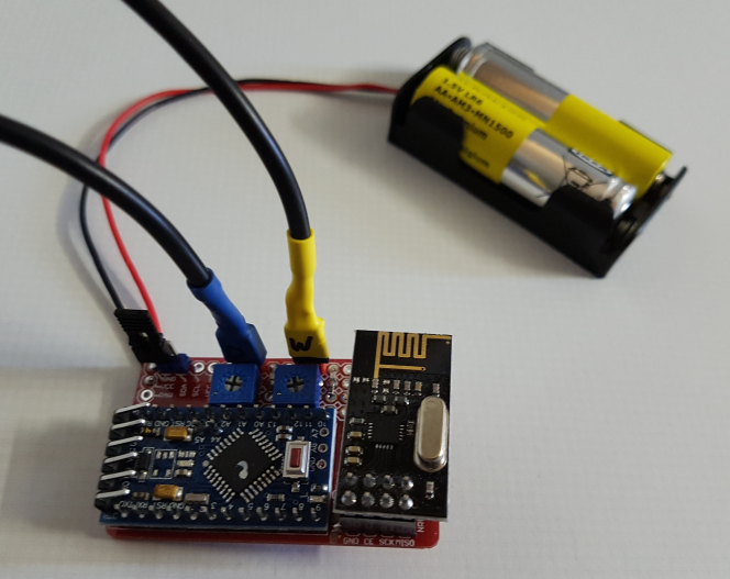
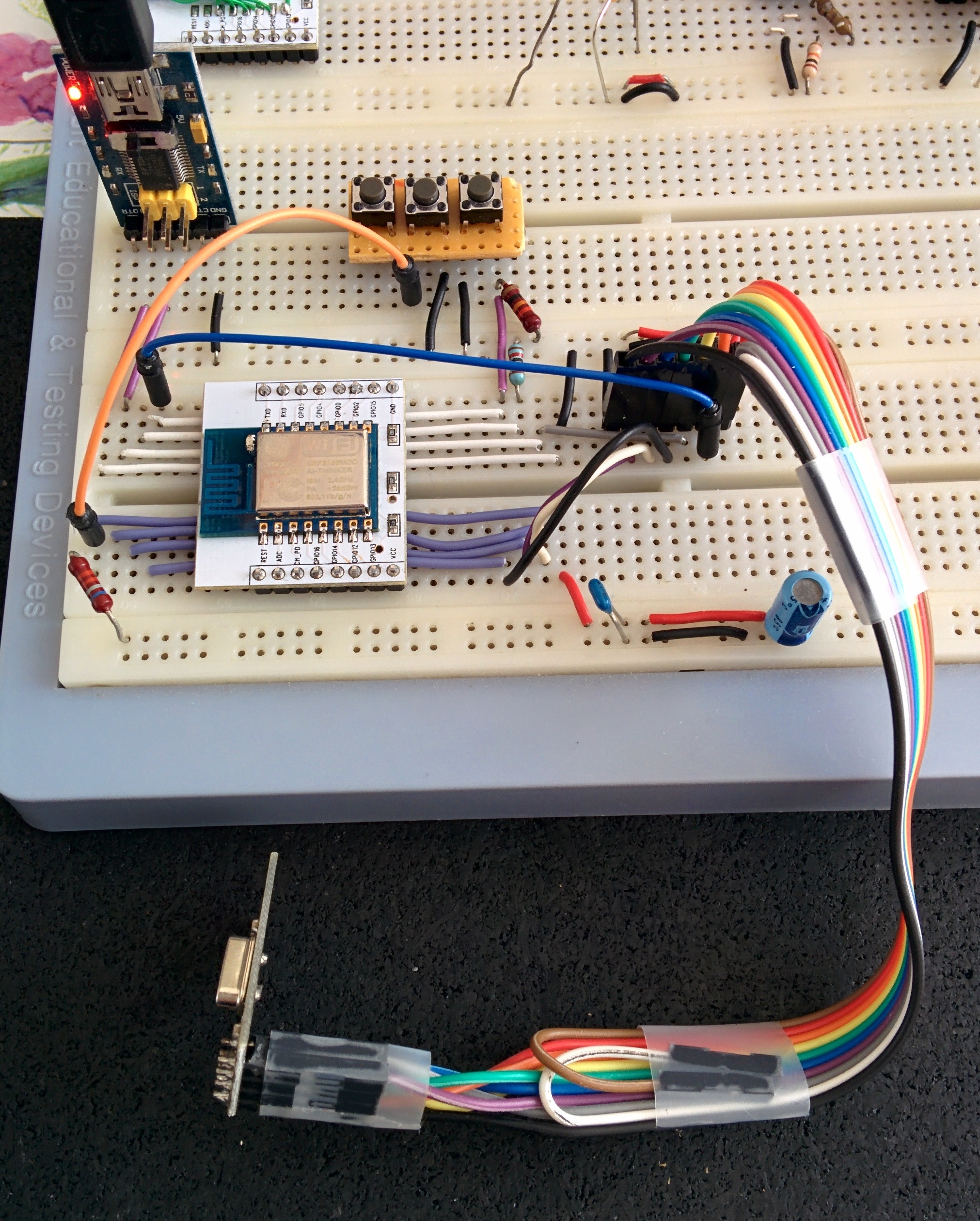
    Connecting the radio:

    • Make sure to use an ESP8266 module which breaks out pins GPIO 4, 12, 13, 14, 15 (e.g. ESP12 module)
    • Connect the radio as described in the header of the gateway code.
    • Connect the other signals as described in the header of the gateway code.
    • I mounted two switches (for reset & bootload) which your ESP8266 may already be equipped with (e.g. the NodeMCU boards have them most of the time)
    • I use an FTDI USB->Serial converter to connect the ESP8266 to my PC, which outputs levels at 3.3V. This is very important as the ESP8266 cannot officially handle 5V signals, and cheap USB->Serial converters often output at 5V levels. When in doubt, please check before connecting!
    • Power both the ESP8266 and the nRF24L01+ from a separate 3.3V power supply. The 3.3V supply from many USB->Serial converters is often too weak.
    • Decouple the power supply with a large capacitor (e.g. 1000uF) and 100nF, to buffer the input and suppress any noise.

    Downloading your sketch:

    • Start wit a low upload speed (e.g. 9600baud). It will take ages to download, but I sometimes have issues downloading at high speeds.

    • Press reset + bootload buttons.

    • Keep bootload pressed while releasing reset

    • After a few seconds release bootload.

    • The ESP8266 is now in bootload mode, and ready to download your code.

    • Choose Upload in the Arduino IDE

    • After some time (a lot of dots) upload should finish and your code starts. The serial monitor (115200 baud) shows the progress:

        ESP8266 MySensors Gateway
        Connecting to SSID
        ...........Connected!
        IP: 192.168.1.119
        0;0;3;0;9;gateway started, id=0, parent=0, distance=0
        0;0;3;0;9;read: 123-123-0 s=1,c=1,t=24,pt=5,l=4,sg=0:2810347
        123;1;1;0;24;2810347
      
    • This text will be preceded by some garbage from the bootloader (it outputs at a lower baudrate)

    • The IP address of the WiFI gateway will currently be obtained from a DHCP server.

    Now connect a telnet session (e.g. putty) to the IP address mentioned in the serial output (192.168.1.119 in this case), port 5003 and send some serial commands!

    Development

  • MySensors booth at Eindhoven Maker Faire!
    YveauxY Yveaux

    The MySensors core team is proud to announce our participation in the Eindhoven Maker Faire 2017!

    The event will take place September 2-3 2017, in Eindhoven, The Netherlands and we will be hosting a full size booth.

    We plan to have a static setup, showing MySensors enabled hardware (from Sensebenders to breadboard) and a live scale model of a MySensorized house.
    Any wild ideas or help are very welcome.

    We hope to meet you all in person and have a fun time!

    Update: We devoted a full page on the Faire!

    Announcements

  • What did you build today (Pictures) ?
    YveauxY Yveaux

    Battery powered MySensors Washing machine & dryer monitor, using LDR's to monitor LEDs on front of the appliances.
    Each time a LED toggles, the node wakes from interrupt and sends a message. Easy peasy!
    When a device is ready, I'll get a message on my mobile phone :smile:

    0_1511607742913_upload-656fdf4c-6707-4a8b-a58c-ef7e74fe1b9f

    0_1511607798459_upload-0183f0a1-571d-45e6-8ecc-b4a33fd9c4e9

    Still need to stuff it in an enclosure...

    General Discussion

  • Windows PopCom tool shows which USB serial ports are available
    YveauxY Yveaux

    I bumped into this handy Windows tool which shows a notification when USB Serial ports are connected or disconnected:

    https://github.com/avishorp/PopCom

    "PopCom is a COM port plug-in/plug-out notifier. Whenever a USB device that emulates a COM port is connected to the computer, a pop-up will be displayed, describing the device that has been plugged in and the COM number assigned to it. This pop-up helps determinig the COM number assigned to each device, a number that is required for communicating with it."

    0_1534241461629_2bd3169b-943b-4611-b04f-6718576760b0-image.png

    As we are plugging serial devices all the time it can be of use to you too!

    Enjoy!

    General Discussion

  • 💬 MySensors @Eindhoven Maker Fair 2017 2-3 September
    YveauxY Yveaux

    Hey guys!

    Just a quick update on the Eindhoven Maker Faire !
    Yesterday we had the first day. @hek, @tbowmo, @scalz, @sincze , @marceltrapman and myself were present at our booth:

    0_1504423218280_upload-382f9719-745f-4791-be51-acbf7d061575

    We had a huge amount of visitors! Many were already familiar with MySensors and we convinced the others to at least have a look a out site :smile:
    The kids loved the automated dollhouse we have on display!

    0_1504423594968_upload-5288f931-5610-4c38-88f9-27bfbd64dae0
    Today we continue with the second day, so you still have one more change to meet us IRL!

    Eindhoven Maker Faire
    11:00 - 18:00
    Klokgebouw 50
    5617 AB Eindhoven
    The Netherlands

    See you there!

    Announcements

  • Good-looking way to control dimmer?
    YveauxY Yveaux

    @mfalkvidd How about a capacitve touch dimmer (rotary, on/off or linear, whatever you like) ?
    Most electricity wall mount systems (e.g. Busch Jaeger, Gira) have 'blind covers' which you can easily fit a capacitive touch pcb behind:

    0_1460356031337_blindafdek.PNG

    Use a chip like MPR121 to readout the capacitive touch PCB and translate it into roraty movements, clicks, whatevers...

    General Discussion

  • 💬 MySensors @Eindhoven Maker Fair 2017 2-3 September
    YveauxY Yveaux

    @gohan I'll probably do a writeup of the house anywhere soon. Please give me some time to process and recover from the Faire :grin:

    Announcements

  • What did you build today (Pictures) ?
    YveauxY Yveaux

    A temperature controlled PWM fan controller for my DPS5005 power supply!

    0_1513282712833_b39ad537-771a-4175-bb65-07a980b2b734-image.png

    The original 2-wire fan that came with the power supply casing made an incredible amount of noise.
    Using PWM to reduce its velocity made it even more noisy :imp:

    So, I made a fresh start and ordered a quality fan (almost as expensive as the whole casing...)

    Using nothing more than a 5V pro mini, piezo speaker, DS18B20 temperature sensor and a resistor I made a full fledged fan controller ;-)

    It takes the current temp from the DS18B20 (which will be mounted on the heatsink) and ramps up the fan linearly in the 30..60 C range. Below 30 C, the fan is off.
    If RPM readback indicates a stalled fan, or DS18B20 returns wrong values the buzzer will force me to invest what's wrong :muscle:

    General Discussion

  • Fun with magnetometer / digital compass sensors
    YveauxY Yveaux

    Attached the HMC5883L to my water meter using some putty (just stuck it on the edge near the metal magnet on the big red arrow):

    0_1458070009000_2016-03-15 20.11.11.jpg

    I let the water run for a while and spilled around 20 litres (0.02m3). You can see the magnet has moved from the 5-digit to the 7-digit:

    0_1458070013698_2016-03-15 20.14.20.jpg

    Next is the chart of the HMC5883L's X/Y/Z readings (Range 8_1GA, average over 8 samples, 1 sample (horizontal pixel) per second):

    0_1458070295145_Naamloos.png

    You can clearly see the sensor readings starting to change when the valve opens and stop changing when it's close again!
    I didn't want to spill 100 litres just for a quick test, but I expect the curves to be sinusodial, and certainly periodic with the turning of the magnet.
    The position of the sensor isn't critical at all (in contrast to all other water meter sensors I've seen), you could even stick it on the closed lid of the water meter!
    Every position will generate a different swing of the X/Y/Z signals, so some clever software is required to translate this into (partial)rotations of the magnet.

    BTW I used this library and modified HMC5883L_simple.ino to output the data for the Arduino plotter.

    Hardware

  • [SOLVED] Sleep dont run
    YveauxY Yveaux

    This information is outdated. An error in the ATMega328P datasheet has been confirmed. See https://forum.mysensors.org/topic/6572/sleep-with-interrupt-only-works-with-level-low

    @AWI Ok, last reply :simple_smile:

    I'll have to dwell a little to explain how the AVR works and what its limitations are regarding sleeping, and how the MySensors library handles it.

    For AVR architecture, the MySensors library uses the 'Power-Down mode' when sleeping.
    I'll focus on ATMega328P here, for which the datasheet states the possible wake-up sources:

    0_1490722068118_upload-b2cbd80d-2c88-4e52-8bae-c46adb341c4f

    So in our case that's INT and WDT (TWI Address match is for i2c slave implementations).
    When a timeout parameter is passed to a sleep() function of the MySensors library the watchdog (WDT) will be used to wake after the specified timeout. If timeout is set to 0 (and wake-up from interrupts is specified) the watchdog will be completely disabled to save some more power.
    When an interrupt source is passed to a sleep() function of the library it will configure INT0 and/or INT1 to wake up the ATMega328.
    Note point 3, as only level interrupts (more precise LOW in case of ATMega328, thanks @AWI for reminding me) can be used as a wake-up source.
    Many posts here use RISING/FALLING/CHANGE as wake-up source for ATMega328 which is not supported by the ATMega328P and thus not supported by the MySensors library. Although people claim it is working for them you are on your own when using the chip out of spec and can expect strange behavior!

    The datasheet continues in detail on the power-down mode:

    0_1490721842267_upload-e4216667-02ab-4505-989f-e2b14c8edfaf

    The MySensors library disables brown-out to save some power. Serial interface address match and pin change interrupt are not used by the library.
    Pay special attention to the note: Waking the AVR from a INT0/INT1 interrupt will require the LOW level to remain for the startup-time, or the interrupt will not trigger. This means that only when the level is held long enough the library will be able to detect it woke from the external interrupt. If the level is not held at least the startup-time, it will assume it woke because of the total sleep time expired, and return MY_WAKE_UP_BY_TIMER (value -1).

    This start-up time depends on the clock frequency and fuse bits, which for e.g. an 8MHz Arduino Pro Mini comes down to 2ms.

    So just remember: In the MySensors library, only use LOW level interrupts to wake an ATMega328 from sleep and assure the interrupt level remains constant for at least the start-up time!

    @AWI Your third example is out-of spec (CHANGE interrupt) and behavior is therefore undefined. If it seems to work, you're lucky...

    This information is outdated. An error in the ATMega328P datasheet has been confirmed. See https://forum.mysensors.org/topic/6572/sleep-with-interrupt-only-works-with-level-low

    Troubleshooting

  • Wireless nRF24L01+ sniffer for MySensors
    YveauxY Yveaux

    Ok, brace yourself! :zap:

    I finally had the time to write on my blog about the wireless network sniffer I've been working on lately.
    For the impatient see:

    • http://yveaux.blogspot.nl/2014/07/nrf24l01-sniffer-part-1.html
    • http://yveaux.blogspot.nl/2014/07/nrf24l01-sniffer-part-2.html
    • http://yveaux.blogspot.nl/2014/07/nrf24l01-sniffer-part-3.html

    This wireless sniffer allows you to capture traffic on air between multiple nodes of your MySensors network and is able to even capture packets with invalid CRC Values. The amount of CRC errors gives a fair indication of link quality, which is not provided by the nRF24.

    The sniffer in action:
    http://www.youtube.com/embed/wxjxm0LnkAk

    Actual capturing is performed by an nRF24L01+ module connected to an Arduino (we all known how to do that ;-) ). No other hardware is required.

    A small piece of software (currently only for Windows, sorry @hek) reads the packet data from the sniffer and forwards it to Wireshark, a network protocol analyzer.
    Wireshark then allows you to inspect the packages from high-level down to the individual bits, filter by content, and analyze statistics.
    Details are all in the blog posts. Last post in this series, which is yet to be written, will dive into using Wireshark and getting useful information from it.
    I didn't want to keep this tool to myself until finally finished and documented, so there can (will?) still be some bugs left...

    Please discuss any issues/ideas/suggestions in here or in my blog.

    Happy sniffin' to all of you!

    Development omg sniffer wireshark nrf24l01+

  • 💬 MySensors @Eindhoven Maker Fair 2017 2-3 September
    YveauxY Yveaux

    Today I posted a full write up of the dollhouse. Find it here: https://www.mysensors.org/build/dollhouse

    Announcements

  • Your workshop :)
    YveauxY Yveaux

    @Matt I like the chainsaw/oscilloscope combo :stuck_out_tongue_winking_eye:

    General Discussion

  • A small NRF24L01 chip comparison
    YveauxY Yveaux

    @alowhum By the way, I finished an extension for the nRF24Doctor about a week ago to display the nRF24 received power spectrum:

    0_1536688587355_8de2f048-1b75-44ac-bcee-87368ca7a8be-image.png

    Between channels 0 and 125 you see a little 'chart' which has a clear peak around the center. The little dot above the chart is an indicator which shows the selected channel (61), frequency (2.461GHz) and Wifi channel (11) at the bottom row.

    The peak in the chart is caused by my Wifi at channel 11 ;-)

    Hardware

  • Why I quit using MySensors for actuators
    YveauxY Yveaux

    @NeverDie Simple said: Buffer messages at nodes until they receive an acknowledge that the message was delivered succesfully. Retry sending the message after some time if the acknowledge does not arrive.
    The principle is simple, but the devil is in the details :smiling_imp:

    General Discussion

  • Calibrating nRF24 pcb antennas
    YveauxY Yveaux

    I ran into this article that uses MySensors and the nrf-doctor to correct issues with Pcb antennas on nRF24 modules.
    I didn't try it, but seems to deserve a mention at this forum!

    General Discussion

  • Visual feedback (leds) @ error
    YveauxY Yveaux

    @sundberg84 the indication system in MySensors allows a user's sketch to receive events each time the MySensors stack does something 'meaningful' or detects an error condition.
    The core/MyIndication.h file contains an enum indication_t that defines all events that will be generated by the stack; e.g. INDICATION_TX indicates a message is about to be sent over the air to a node and INDICATION_ERR_TRANSPORT_FAILURE indicates a problem with the transport layer (radio defect).

    The stack itself implements a setIndication() handler for these events (I removed the #ifdefs for readability):

    void setIndication( const indication_t ind )
    {
        if ((INDICATION_TX == ind) || (INDICATION_GW_TX == ind)) {
            ledsBlinkTx(1);
        } else
        if ((INDICATION_RX == ind) || (INDICATION_GW_RX == ind)) {
            ledsBlinkRx(1);
        } else
        if (ind > INDICATION_ERR_START) {
            // Number of blinks indicates which error occurred.
            ledsBlinkErr(ind-INDICATION_ERR_START);
        }
    }
    

    As you can see it blinks the Tx led one time when an INDICATION_TX or INDICATION_GW_TX event is received, it blinks the Rx led one time when an INDICATION_RX or INDICATION_GW_RX event is received, and it blinks the error led a number of times, depending on the actual error event code.

    The error events are defined in a separate range of the indication_t enum, starting from INDICATION_ERR_START which is defined as 100.
    As you see in the code above, in case of errors the INDICATION_ERR_START value will be substracted from the actual event value.
    The first actual error in indication_t is defined as INDICATION_ERR_HW_INIT (its value is 101), and will therefore cause the error led to blink 1 time.
    The next error in indication_t is defined as INDICATION_ERR_TX(its value is 102), and will therefore cause the error led to blink 2 times, etc.

    The fun thing is, you can define your own handler which receives exactly the same events as this piece of LED blink code from the stack does!

    To enable it, define MY_INDICATION_HANDLER before the MySensors-include in your sketch:

    #define MY_INDICATION_HANDLER
    #include <MySensors.h>
    

    Now, anywhere in your sketch add the following function:

    void indication( const indication_t ind )
    {
        // .. act on events you're interested in ..
        // Not a very useful example, but I hope you get the point
        if (INDICATION_TX == ind) {
            // turn my garden lights on
            digitalWrite(GARDEN_LIGHTS_PIN, HIGH);
        }
        if (INDICATION_RX == ind)
            // turn my garden lights off
            digitalWrite(GARDEN_LIGHTS_PIN, LOW);
        }
    }
    

    Make sure to not stay long in this function, as it will block the MySensors stack from running! Do the bare minimum of what you need to do and exit. Don't use delay() and the like, and don't call any MySensors functions from it!

    The gateway from @Japio uses the indication() function. (Note that he doesn't define MY_INDICATION_HANDLER as it was written for an older version of the library).

    My dollhouse sketches also use the indication() handler, but I wrapped it into a library as the implementation is shared for all sketches.

    This dollhouse library also uses my Arduino LedPattern library what was the other thing suitable for your application.
    Instead of having to code all kinds of different LED blinking patterns, you can simply define them as (repeating) sequences in your code and call an update function at regular intervals. The library automagically blinks and/or fades the LEDs in the defined pattern without having to worry about a thing.

    Definition of a basic sequence to fade a LED looks like:

    // A repeating sequence of fading the LED to on
    // in 50 cycles, then fading back to off in 100 cycles.
    const uint8_t myPattern[] = {
        LedPattern::CMD_SET, OFF,
        LedPattern::CMD_REPEAT, LedPattern::repeatForever, 
            LedPattern::CMD_FADETO,  50, LED_ON,
            LedPattern::CMD_FADETO, 100, LED_OFF,
        LedPattern::CMD_ENDREPEAT
    };
    

    To start the fading pattern, just call

    pattern.start(myPattern);
    

    And in your loop() you call update regularly:

    void loop()
    {
      // Update pattern state. LED gets updated and the pattern gets parsed.
      pattern.update();
      
      // Wait 1 time (10ms) cycle before updating again.
      delay(10);
    }
    

    Another option is to call update() from e.g. a timer interrupt.
    The library supports regular LEDs (or garden lights ;-) ), RGB LEDs, NeoPixels and FastLED library. See the readme and examples that come with it.

    Now, if you look again at the dollhouse sketch library, you see I defined a number of different blinking patterns for different states of the stack:

    const uint8_t ledPatternJoin[] = {
      LedPattern::CMD_REPEAT, LedPattern::repeatForever,
      LedPattern::CMD_SET, LED_ON,
      LedPattern::CMD_WAIT, 10,
      LedPattern::CMD_SET, LED_OFF,
      LedPattern::CMD_WAIT, 50,
      LedPattern::CMD_ENDREPEAT
    };
    
    // ...
    
    const uint8_t ledPatternTxRx[] = {
      LedPattern::CMD_SET, LED_ON,
      LedPattern::CMD_WAIT, 1,
      LedPattern::CMD_SET, LED_OFF,
      LedPattern::CMD_FINISHED
    };
    

    These patterns are started from the indication() handler I explained above (simplified):

    void indication( const indication_t ind )
    {
      if (     INDICATION_TX == ind)
           || (INDICATION_GW_TX == ind)
           || (INDICATION_RX == ind)
           || (INDICATION_GW_RX == ind) )
        {
           ledPattern.start(ledPatternTxRx);
        }
      } else if (INDICATION_FIND_PARENT == ind)
      {
        ledPattern.start(ledPatternJoin);
      } // ... else ... 
    }
    

    So any TX/RX event from the stack will play the ledPatternTxRx sequence, and when the node starts searching for a parent the ledPatternJoin sequence is played!
    You might want to block starting new patterns once a pattern is playing to prevent getting a blinking mess when events come in rapidly. The ledPattern.finished() function tells you if a pattern is currently playing or not.

    Note that these sketches use MsTimer2 to time the LedPattern update() calls.

    Combining these two techniques in your gardenlights will certainly drive your neighbours crazy :stuck_out_tongue_winking_eye:

    Feature Requests

  • Hacking a wireless weather station display
    YveauxY Yveaux

    Hey there!

    In the past days I succeeded in taking over an indoor wireless weather display and feed it the data from a bunch of weather sensors.

    gif_im_color_dither_32_6267298df7.gif

    An 868Mhz transmitter is fed with sensor data obtained through a MySensors network, which will then be shown on the display.
    A description of the project can be found at my blog: http://yveaux.blogspot.nl/2015/08/hacking-wireless-weather-display.html

    Enjoy!

    My Project

  • Your workshop :)
    YveauxY Yveaux

    By popular demand (@hek :wink:), my main workplace:

    0_1459682326478_2016-04-03 12.25.11.jpg

    Semi-organized chaos :metal: and some interesting new projects in the making!

    General Discussion

  • LEDs on GW and nodes aren't working as expected
    YveauxY Yveaux

    @jpaulin Fix is now in development (also tested on ESP8266) and sleeping issue is also solved.
    Node will now finish its LED pattern before going to sleep.

    Bug Reports
  • Login

  • Don't have an account? Register

  • Login or register to search.
  • First post
    Last post
0
  • MySensors
  • OpenHardware.io
  • Categories
  • Recent
  • Tags
  • Popular