@naty6458 no need to be sorry. I keep hoping there is a better answer than what I found, and each time it is asked I learn something, so there is at least one person that is happy you asked.
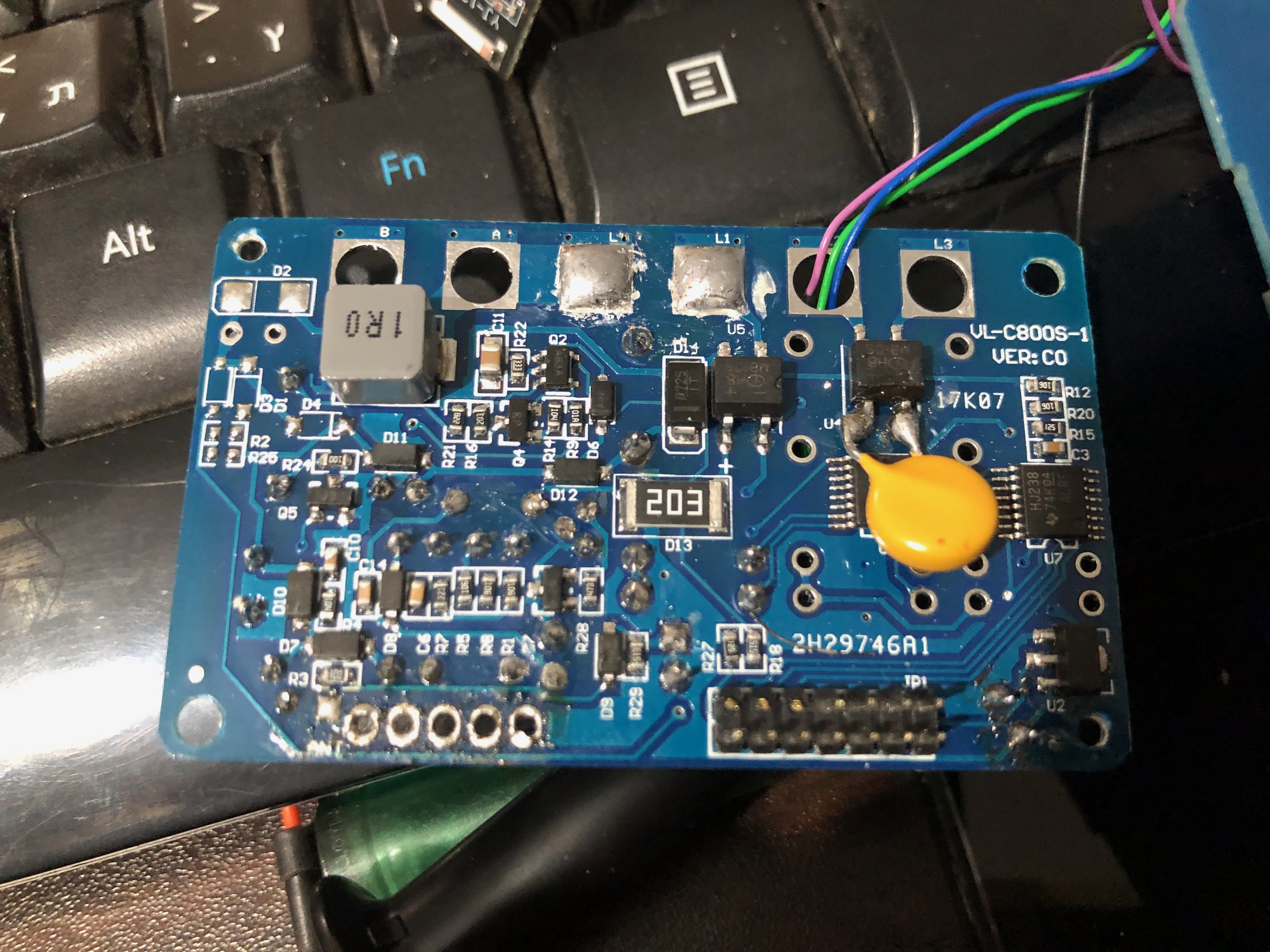
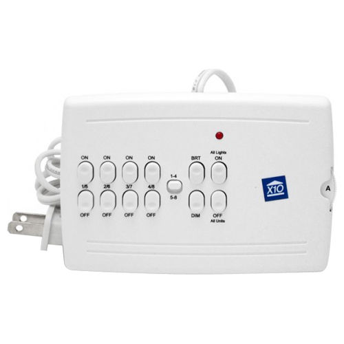
My plan is optocouplers, maybe a rechargeable coin cell to help power them. I want to connect to the pins for the rf receiver. I should be able to send the same code the remote uses to turn it on and off. Since I wont be sending codes often the coin cell should be fully charged most of the time, so the low capacity (~23mah) shouldn't cause a problem, unless someone flicks the lights on and off repeatedly.
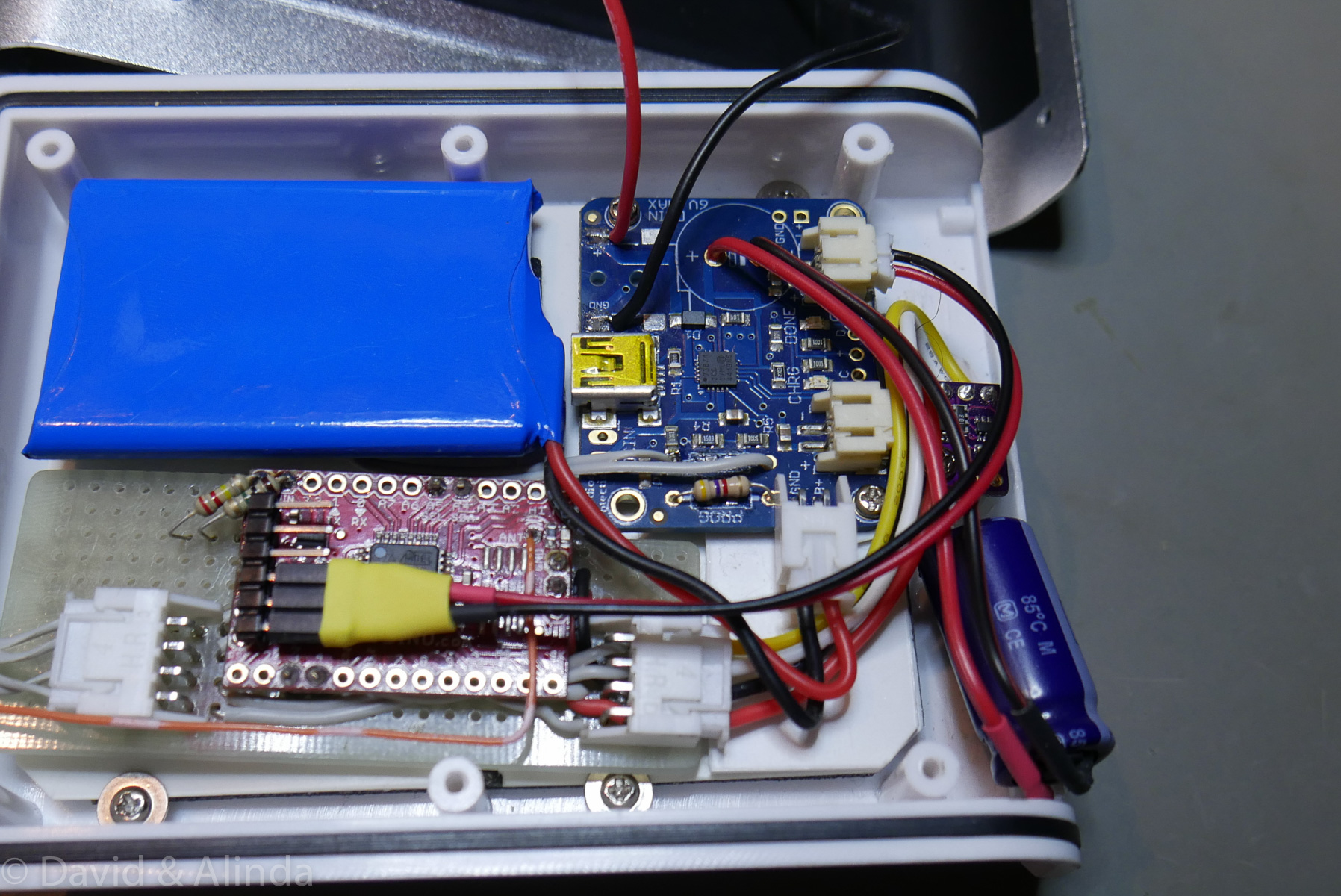
I'll power the arduino/rs485 module separately.