Skip to content

Hardware

Talk about fun sensor hardware, MCUs, PCBs and how to power your sensors here.
1.8k Topics 18.3k Posts
  • Any one using gps tracker?

    Locked
    7
    1 Votes
    7 Posts
    2k Views
    D
    @mfalkvidd might be you are right:blush: but actually if it is good, i am positive with these. lol
  • Processing audio signal in sensor

    2
    0 Votes
    2 Posts
    744 Views
    mfalkviddM
    Hi @Afnan Welcome to the MySensors community. While this is an interesting question, I don't think youl'll find many audio analysis experts in this forum. We're mainly focused on home automation. What results did you get when you tried in Matlab with the lower sample rate and shorter duration? Will the mcu be able to perform the required calculations quick enough? How much ram will the calculations require? Will the required libraries fit in the flash on the mcu? Linking to your question on Stack Overflow so people don't waste time answering here if there already has been posted an answer there: https://stackoverflow.com/questions/44609083/processing-audio-signals-in-matlab-vs-sensor
  • Arduino Nano issue

    13
    0 Votes
    13 Posts
    3k Views
    qqlapralineQ
    @mfalkvidd, nice pickup ! Thanks !
  • Low power PIR breakout board for Mysensors and evaluation

    35
    6 Votes
    35 Posts
    14k Views
    scalzS
    @Nca78 i didn't forget what i said ;) Here, from the logic analyzer, a screenshot of my lib refactor for e931.96. Write (2nd row) and read back (1st row) : ok [image: 1497530549153-e931.96-resized.png] just a few things i would like to check, and i'll release the lib, as this chip will be optional on one of my new boards.
  • relays

    relay water pump
    5
    0 Votes
    5 Posts
    1k Views
    gohanG
    If you can figure out a way to control them maybe using an optocoupler, it could be an option
  • Trace to antenna?

    6
    0 Votes
    6 Posts
    2k Views
    E
    Quick followup: After I started looking for them, i saw quite a few traces like this. A lot of them put rows of vias in the groundplane along the trace. I see that this would change the impedance taken from the calculator if they are close (since there is more ground around), but should there be any closeby connection between top and bottom ground? At the beginning and/or end, e.g.?
  • My Sensor node "motherboard" (MySensorsNode)

    72
    12 Votes
    72 Posts
    36k Views
    AnticimexA
    @bilbolodz well, no it is 2mm pitch.
  • Low profile header connectors

    5
    1
    1 Votes
    5 Posts
    2k Views
    mfalkviddM
    @dbemowsk I'm at the wrong side of the Atlantic to check, but I think the entire thin part fits inside the header.
  • This topic is deleted!

    1
    0 Votes
    1 Posts
    106 Views
    No one has replied
  • NRF24L01+ genuine vs. counterfeit - checked some modules

    36
    8
    12 Votes
    36 Posts
    12k Views
    M
    Many thanks for your advice. For good or bad, reality is never black or white, but shades of grey. I already thought on switching to RFM69 or try the new LoRa but that would mean switching around 15 already functioning nodes, together with the associated cost. Out of those 15, the few showing problems to communicate with the gw are the furthest ones; those are where where I'm planning to give an oportunity to the new modules linked above. By the way, my gateway already has one PA+LNA module inside, but with an external whip antenna. 
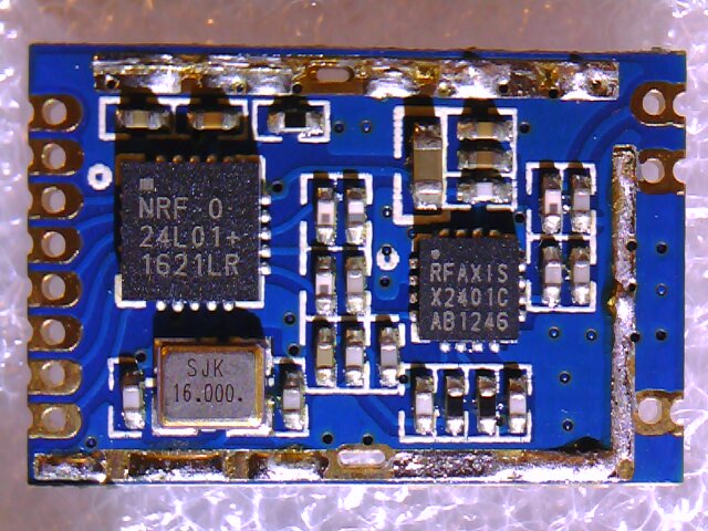
I actually just installed the first one. I removed the "normal" nrf24 and switched by one of these in the most problematic node. Soldering the wiring into the 1.27mm holes was a challenge; some adapters that should make connection easier should be about to arrive but I was eager to run some tests. For the moment this module seems to have less problems to connect to the gateway - of course I won't be able to draw more final conclusions until it's been in use for some days, but for the moment it looks promising. Of course, should they finally not show a significant improvemen over the former modules, I'll consider testing some of the other options.
  • Buy big amount of Arduino nano with FTDI

    5
    0 Votes
    5 Posts
    1k Views
    Richard van der PlasR
    ive good good experience with the BAITE online store, fast shipping and offering a price by 10
  • Distance sensor power

    10
    0 Votes
    10 Posts
    3k Views
    zboblamontZ
    @fhenryco Yes to the first. The 5v supply will give a 5v logic output from the sensor on the echo pin. That must be reduced. Below a good 5v supply these sensors has been found to give unreliable results, although there are many different model numbers which look identical, so it is a bit of a minefield. No to the second, this particular sensor will not work reliably at other than a good 5v supply. The 3v3 is sufficient to give a logical high to the sensor to initiate measurement on this 5v device, a 5v trigger would also work from a 5v board. The echo output is at the sensor voltage of 5v level. If I recall one past thread on this, the poster was getting weird readings using a 3AA supply over time, the booster gave him rock solid readings until the batteries reached 1v.
  • What kind of wireless is recommended ?

    2
    0 Votes
    2 Posts
    711 Views
    mfalkviddM
    @donnib A 3.3V Arduino Pro Mini is recommended for battery powering, see https://www.mysensors.org/build/battery for details. For a comparison between rfm69 and nrf24l01+, see https://forum.mysensors.org/topic/3993/nordic-or-hoperf-radio nrf and rfm use roughly the same amount of power, so battery-wise there is no big difference.
  • Raspi GPIO as input to gateway

    6
    0 Votes
    6 Posts
    1k Views
    gohanG
    There is a WIKI page on Domoticz site about GPIO
  • 3.3 or 5v tranformer for mysensors projects

    26
    0 Votes
    26 Posts
    8k Views
    gohanG
    @DavidZH said in 3.3 or 5v tranformer for mysensors projects: This is one area I'm quite envied with the US building methods. Well at least our houses don't fly away with a tornado (at least mine didn't) :D Anyway I think the best approach in retrofitting an "old" house to home automation stuff is to be flexible and also include, when needed, commercial product like zwave switches that are miniaturized to fit in the size of a light switch.
  • Sensebender pinout

    5
    0 Votes
    5 Posts
    1k Views
    A
    Nice, thanks for helping guys! :+1:
  • Use this instead of NRF24L01+ ?

    3
    0 Votes
    3 Posts
    1k Views
    Matt BriggsM
    Thanks for the info. Just getting started trying to do some of this and am biting off more than I can chew. I need to get back to the basics and learn rather than jumping around too much, but there are some great things to do and I don't want to wait! Reading the forums on different topics I have seen that the cheap way is the best way to get messed up and discouraged.
  • USNAP (ANSI/CEA-2045) Smart-Grid interface

    2
    0 Votes
    2 Posts
    1k Views
    PhracturedBlueP
    I think I got confused somewhere along the way. I do not think the protocol is actually MODBUS as Modbus does not appear to use a start-of frame bit and specifies a CRC rather than a simple checksum. The water heater is a Reliance DHPST hybrid water heater (electric + Heat Pump) Data on RS485 is transmitted at 19200 baud Data is 1 startbit, 8 data bits, 1 'start of frame' bit, and 1 stop bit/ The 'start of frame' bit is 1 for the 1st byte, and 0 for all remaining bytes. The last byte is a single 1-byte sum of all previous bytes of the frame. This represents most of the packets I have seen (I have removed the 'start of packet' bit: (3) : 90 00 90 (64) : 40 08 1e 00 00 00 03 00 78 00 00 00 00 00 00 71 44 74 6a 49 47 30 00 02 00 00 00 00 00 00 00 00 00 00 00 00 00 00 00 69 cd 00 00 00 00 16 02 00 00 00 09 00 00 00 00 00 00 41 08 00 00 50 00 26 (30) : 40 0b 0d 02 00 62 00 5a 00 5e 00 52 00 00 00 ff ff 00 00 00 00 00 00 00 00 00 01 00 02 c7 (3) : 8c 00 8c (3) : 82 00 82 (8) : 40 00 02 05 00 b2 00 f9 (28) : 40 0d 0c 00 01 00 3c 00 00 00 10 00 78 00 78 01 01 00 00 00 00 00 01 00 00 00 00 99 For anyone interested, the easiest way to read this in linux is to set the INPCK and PARMRK, and then read with 'SPACE' parity. this will generate an error whenever the parity bit is set, that can then be converted into a 'start of frame' bit. Here is some example python code: import serial import termios i ser = serial.Serial(port, 19200, parity=serial.PARITY_SPACE) iflag, oflag, cflag, lflag, ispeed, ospeed, cc = termios.tcgetattr(ser) iflag |= termios.INPCK | termios.PARMRK termios.tcsetattr(ser, termios.TCSANOW, [iflag, oflag, cflag, lflag, ispeed, ospeed, cc]) buf = [] while True: try: b = ord(ser.read(1)) if b == 0xff : b = ord(ser.read(1)) if b == 0x00: b = 0x100 | ord(ser.read()) buf.append(b) except SerialException as e: print(e) I'll follow-up with the bytes I've figured out so far.
  • Sensor Network and rPi's onboard WiFi?

    13
    0 Votes
    13 Posts
    3k Views
    C
    Cool. Many thanks for your prompt and helpful advice, much appreciated.
  • RFM69 and TLC5940

    10
    0 Votes
    10 Posts
    3k Views
    dbemowskD
    Would using shift registers work?

17

Online

11.7k

Users

11.2k

Topics

113.1k

Posts