Getting started with Wemos d1 mini & RFM69HW
-
Hi everyone!
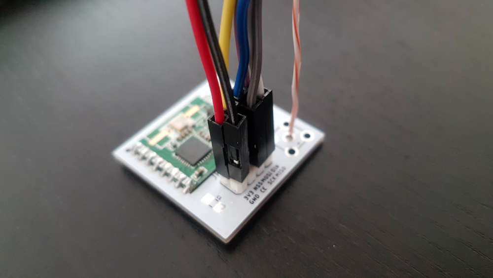
I've tried connecting a wemos d1 mini to a RFM69HW. I have a PCB with headers, connect the pins from the RFM69 to the wemos in the following configuration:
GND GND
3.3V VCC
D1 DIO0
D5 SCK
D6 MISO
D7 MOSI
D8 NSSIt repetitively shows the following on the serial output:
 __  __       ____
|  \/  |_   _/ ___|  ___ _ __  ___  ___  _ __ ___
| |\/| | | | \___ \ / _ \ `_ \/ __|/ _ \| `__/ __|
| |  | | |_| |___| |  __/ | | \__ \  _  | |  \__ \
|_|  |_|\__, |____/ \___|_| |_|___/\___/|_|  |___/
        |___/                      2.3.1

58 MCO:BGN:INIT NODE,CP=RRNNE---,REL=255,VER=2.3.1
73 TSM:INIT
74 TSF:WUR:MS=0
78 TSM:INIT:TSP OK
79 TSM:FPAR``````
Therefor I believe the board and rfm to be ok. As for sketches I've tried the ping pong sketch
Then crashes and restarts.
So I thought there could be a problem with the RFM or PCB. So I connected to a Raspberry pi (compiled in mqtt gw mode.) and get this.
Jul 29 13:08:41 INFO  Starting gateway...
Jul 29 13:08:41 INFO  Protocol version - 2.3.1
Jul 29 13:08:41 DEBUG MCO:BGN:INIT GW,CP=RPNGL---,REL=255,VER=2.3.1
Jul 29 13:08:41 DEBUG TSF:LRT:OK
Jul 29 13:08:41 DEBUG TSM:INIT
Jul 29 13:08:41 DEBUG TSF:WUR:MS=0
Jul 29 13:08:41 DEBUG TSM:INIT:TSP OK
Jul 29 13:08:41 DEBUG TSM:INIT:GW MODE
Jul 29 13:08:41 DEBUG TSM:READY:ID=0,PAR=0,DIS=0
Jul 29 13:08:41 DEBUG MCO:REG:NOT NEEDED
Jul 29 13:08:41 DEBUG MCO:BGN:STP
Jul 29 13:08:41 DEBUG MCO:BGN:INIT OK,TSP=1
Jul 29 13:08:41 DEBUG GWT:RMQ:MQTT RECONNECT
Jul 29 13:08:41 DEBUG connected to 10.0.0.56
Jul 29 13:08:41 DEBUG GWT:RMQ:MQTT CONNECTED
Jul 29 13:08:41 DEBUG GWT:TPS:TOPIC=mysensors-out/0/255/0/0/18,MSG SENT
Jul 29 13:08:41 DEBUG TSM:READY:NWD REQ
Jul 29 13:08:43 DEBUG TSF:MSG:SEND,0-0-255-255,s=255,c=3,t=20,pt=0,l=0,sg=0,ft=0,st=OK:
Jul 29 13:23:41 DEBUG TSF:SAN:OK
I believe that means it is ok, which rules out the RFM69 or the PCB.
So unless someone has an idea what is wrong, any suggestion on how I can connect another rfm69 to another raspberry pi and communicate with the mysensor gateway? Sorry I haven't seen any code for pi as non-gateway. And I only have extra raspberry pi, Wemos d1 mini and an arduino uno clone.
On a side note - could there be insufficient power for the rfm69?
-
I use this setup with this pcb
https://www.openhardware.io/view/392/Minimalist-RFM69HW-Shield-for-Wemos-D1-Mini
#define MY_RFM69_IRQ_PIN D2
#define MY_RFM69_IRQ_NUM MY_RFM69_IRQ_PIN
#define MY_RFM69_CS_PIN D8
It works, but crashes occasionally. I think i need to power the radio from its own supply.
-
Tried D1 & D2, no luck. Using a similar board, requires jumper wires to connect but allows future expansion of the antenna.
Found: https://www.openhardware.io/view/601/NRF24-to-RFM69-adapter
-
For your setup:
( change frequency and HW version)#define MY_RADIO_RFM69 #define MY_RFM69_FREQUENCY RFM69_433MHZ // Set your frequency here #define MY_IS_RFM69HW // Omit if your RFM is not "H" #define MY_RFM69_IRQ_PIN D1 #define MY_RFM69_IRQ_NUM MY_RFM69_IRQ_PIN #define MY_RFM69_CS_PIN D8 // NSS. Use MY_RFM69_SPI_CS for older versions (before 2.2.0)With this setup and GW sketch from MySensors examples I am running this GW almost year without problem.
On Wemos D1// Enable debug prints to serial monitor #define MY_DEBUG // Use a bit lower baudrate for serial prints on ESP8266 than default in MyConfig.h #define MY_BAUD_RATE 9600 // Enables and select radio type (if attached) //#define MY_RADIO_NRF24 #define MY_RADIO_RFM69 #define MY_IS_RFM69HW // Omit if your RFM is not "H" #define MY_RF69_IRQ_PIN D1 #define MY_RF69_IRQ_NUM MY_RF69_IRQ_PIN #define MY_RFM69_CS_PIN D8 // NSS. Use MY_RF69_SPI_CS for older versions (before 2.2.0) //#define MY_RADIO_RFM95 #define MY_GATEWAY_ESP8266 #define MY_ESP8266_SSID "SSID" #define MY_ESP8266_PASSWORD "password" // Enable UDP communication //#define MY_USE_UDP // If using UDP you need to set MY_CONTROLLER_IP_ADDRESS below // Set the hostname for the WiFi Client. This is the hostname // it will pass to the DHCP server if not static. //#define MY_ESP8266_HOSTNAME "sensor-gateway" // Enable MY_IP_ADDRESS here if you want a static ip address (no DHCP) #define MY_IP_ADDRESS 192,168,1,252 // If using static ip you can define Gateway and Subnet address as well #define MY_IP_GATEWAY_ADDRESS 192,168,1,254 #define MY_IP_SUBNET_ADDRESS 255,255,255,0 // The port to keep open on node server mode #define MY_PORT 5003 // How many clients should be able to connect to this gateway (default 1) #define MY_GATEWAY_MAX_CLIENTS 2 // Controller ip address. Enables client mode (default is "server" mode). // Also enable this if MY_USE_UDP is used and you want sensor data sent somewhere. //#define MY_CONTROLLER_IP_ADDRESS 192, 168, 1, 17 // Enable inclusion mode //#define MY_INCLUSION_MODE_FEATURE // Enable Inclusion mode button on gateway //#define MY_INCLUSION_BUTTON_FEATURE // Set inclusion mode duration (in seconds) //#define MY_INCLUSION_MODE_DURATION 60 // Digital pin used for inclusion mode button //#define MY_INCLUSION_MODE_BUTTON_PIN 3 // Set blinking period //#define MY_DEFAULT_LED_BLINK_PERIOD 300 // Flash leds on rx/tx/err // Led pins used if blinking feature is enabled above //#define MY_DEFAULT_ERR_LED_PIN 16 // Error led pin //#define MY_DEFAULT_RX_LED_PIN 16 // Receive led pin //#define MY_DEFAULT_TX_LED_PIN 16 // the PCB, on board LED #if defined(MY_USE_UDP) #include <WiFiUdp.h> #endif #include <ESP8266WiFi.h> #include <MySensors.h> void setup() { // Setup locally attached sensors } void presentation() { // Present locally attached sensors here } void loop() { // Send locally attached sensors data here }``` -
Using a very simple sketch (trying to test after all)
// Enable debug prints
#define MY_DEBUG

#define MY_RADIO_RFM69
#define MY_RFM69_FREQUENCY  RFM69_915MHZ
#define MY_IS_RFM69HW // Omit if your RFM is not "H"
#define MY_RFM69_IRQ_PIN D1
#define MY_RFM69_IRQ_NUM MY_RFM69_IRQ_PIN
#define MY_RFM69_CS_PIN D8 // NSS. Use MY_RFM69_SPI_CS for older versions (before 2.2.0)
#define MY_RFM69_NETWORKID  99

#define MY_BAUD_RATE  115200

#include <MySensors.h>

#define CHILD_ID 1   // Id of the sensor child
int counter =0;

// Initialize motion message
MyMessage msg(CHILD_ID, V_TEMP);

void setup()
{
  Serial.println("Setup completed");
}

void presentation()
{
	// Send the sketch version information to the gateway and Controller
	sendSketchInfo("Test Sensor", "1.0");

	// Register all sensors to gw (they will be created as child devices)
	present(CHILD_ID, S_TEMP);
}

void loop()
{
  Serial.println("Looped");

//	send(msg.set(tripped?"1":"0"));  // Send tripped value to gw

	send(msg.set(counter, 1));
	counter=counter+1;
  sleep(2000);
}
If I disconnect the 3v, it doesn't crash just gives the fail message since it can't communicate with the rfm69. As soon as reconnect it crashes :(
-
Got some good news. Adding the #define MY_RFM69_NEW_DRIVER and now it doesn't crash! Thanks evb and mfalkvidd for the tips.
So, now that the wemos with radio is has the above sketch, just a simple send of a number running.
On the pi I download the main branch, ran:
./configure --my-transport=rfm69 --my-rfm69-irq-pin=22 --my-rfm69-cs-pin=24 --my-rfm69-frequency=915 --my-is-rfm69hw
--my-gateway=mqtt --my-controller-ip-address=127.0.0.1 --my-mqtt-publish-topic-prefix=mysensors-out
--my-mqtt-subscribe-topic-prefix=mysensors-in --my-mqtt-client-id=mysgw1  --my-mqtt-user=UID
--my-mqtt-password=password
then
make
sudo ./bin/mysgw
The output is the same as post 1. They both say they are sending, but neither receive anything. Did I miss some settings? I know in the sketch I specified a network id which I didn't see the option for in the gateway on pi.
@les if the sketch uses a different network id, it will be on a different network. Different networks are, well, different - as in not the same. So there will be no communication between them.
If you need to set network id, set the define as described on https://www.mysensors.org/build/raspberry#advanced If you don't need to set network id, don't set network id.
-
@les if the sketch uses a different network id, it will be on a different network. Different networks are, well, different - as in not the same. So there will be no communication between them.
If you need to set network id, set the define as described on https://www.mysensors.org/build/raspberry#advanced If you don't need to set network id, don't set network id.
@mfalkvidd I figured it had something to do with the network ID, but from what I understand there is no way to specify it on the PI. However in my case I don't need an ID I was just under the impression it was required. So I've removed it. And 1/2 success.
The Pi when starting mysgw still produces the same startup and sends 1 msg out.
On the wemos serial output I see it gets 1 msg from the pi but doesn't progress.
32566 TSM:INIT
32568 TSM:INIT:TSP OK
32570 TSM:FPAR
33075 TSF:MSG:SEND,255-255-255-255,s=255,c=3,t=7,pt=0,l=0,sg=0,ft=0,st=OK:
33814 TSF:MSG:READ,0-0-255,s=255,c=3,t=20,pt=0,l=0,sg=0:
35082 !TSM:FPAR:NO REPLY
35084 TSM:FPAR
35589 TSF:MSG:SEND,255-255-255-255,s=255,c=3,t=7,pt=0,l=0,sg=0,ft=0,st=OK:
37596 !TSM:FPAR:NO REPLY
37598 TSM:FPAR
Is there some extra steps required to pair them or get the two to communicate?
-
also worth noting I am manually running sudo bin/mysgw not as a service. As the instructions sound like it can be tested this way to make sure it is working.
-
@mfalkvidd I figured it had something to do with the network ID, but from what I understand there is no way to specify it on the PI. However in my case I don't need an ID I was just under the impression it was required. So I've removed it. And 1/2 success.
The Pi when starting mysgw still produces the same startup and sends 1 msg out.
On the wemos serial output I see it gets 1 msg from the pi but doesn't progress.
32566 TSM:INIT
32568 TSM:INIT:TSP OK
32570 TSM:FPAR
33075 TSF:MSG:SEND,255-255-255-255,s=255,c=3,t=7,pt=0,l=0,sg=0,ft=0,st=OK:
33814 TSF:MSG:READ,0-0-255,s=255,c=3,t=20,pt=0,l=0,sg=0:
35082 !TSM:FPAR:NO REPLY
35084 TSM:FPAR
35589 TSF:MSG:SEND,255-255-255-255,s=255,c=3,t=7,pt=0,l=0,sg=0,ft=0,st=OK:
37596 !TSM:FPAR:NO REPLY
37598 TSM:FPAR
Is there some extra steps required to pair them or get the two to communicate?
-
I'm going to take a stab in the dark that the issue is with the pi node since the wemos received and sent and I don't see any message on the pi for anything being received.
With the debuging enabled on the client I get:
 __  __       ____
|  \/  |_   _/ ___|  ___ _ __  ___  ___  _ __ ___
| |\/| | | | \___ \ / _ \ `_ \/ __|/ _ \| `__/ __|
| |  | | |_| |___| |  __/ | | \__ \  _  | |  \__ \
|_|  |_|\__, |____/ \___|_| |_|___/\___/|_|  |___/
        |___/                      2.3.1

12703 MCO:BGN:INIT NODE,CP=RPNNE---,REL=255,VER=2.3.1
12893 TSM:INIT
12908 TSF:WUR:MS=0
12928 RFM69:INIT
12946 RFM69:INIT:PIN,CS=15,IQP=5,IQN=5
12988 RFM69:PTX:LEVEL=5 dBm
13017 RFM69:DUMP:Registers Address | HEX value
13067 RFM69:DUMP:REG=0x01 Value=0x04
13106 RFM69:DUMP:REG=0x02 Value=0x00
13145 RFM69:DUMP:REG=0x03 Value=0x02
13183 RFM69:DUMP:REG=0x04 Value=0x40
13222 RFM69:DUMP:REG=0x05 Value=0x03
13261 RFM69:DUMP:REG=0x06 Value=0x33
13300 RFM69:DUMP:REG=0x07 Value=0xe4
13338 RFM69:DUMP:REG=0x08 Value=0xc0
13377 RFM69:DUMP:REG=0x09 Value=0x00
13416 RFM69:DUMP:REG=0x0a Value=0x41
13454 RFM69:DUMP:REG=0x0b Value=0x00
13493 RFM69:DUMP:REG=0x0c Value=0x02
13532 RFM69:DUMP:REG=0x0d Value=0x92
13570 RFM69:DUMP:REG=0x0e Value=0xf5
13609 RFM69:DUMP:REG=0x0f Value=0x20
13648 RFM69:DUMP:REG=0x10 Value=0x24
13687 RFM69:DUMP:REG=0x11 Value=0x57
13725 RFM69:DUMP:REG=0x12 Value=0x09
13764 RFM69:DUMP:REG=0x13 Value=0x1a
13803 RFM69:DUMP:REG=0x14 Value=0x40
13841 RFM69:DUMP:REG=0x15 Value=0xb0
13880 RFM69:DUMP:REG=0x16 Value=0x7b
13919 RFM69:DUMP:REG=0x17 Value=0x9b
13958 RFM69:DUMP:REG=0x18 Value=0x88
13996 RFM69:DUMP:REG=0x19 Value=0xe2
14035 RFM69:DUMP:REG=0x1a Value=0xe2
14074 RFM69:DUMP:REG=0x1b Value=0x40
14112 RFM69:DUMP:REG=0x1c Value=0x80
14151 RFM69:DUMP:REG=0x1d Value=0x06
14190 RFM69:DUMP:REG=0x1e Value=0x10
14229 RFM69:DUMP:REG=0x1f Value=0x00
14267 RFM69:DUMP:REG=0x20 Value=0x00
14306 RFM69:DUMP:REG=0x21 Value=0x00
14345 RFM69:DUMP:REG=0x22 Value=0x00
14383 RFM69:DUMP:REG=0x23 Value=0x02
14422 RFM69:DUMP:REG=0x24 Value=0xff
14461 RFM69:DUMP:REG=0x25 Value=0x40
14499 RFM69:DUMP:REG=0x26 Value=0x07
14538 RFM69:DUMP:REG=0x27 Value=0x80
14577 RFM69:DUMP:REG=0x28 Value=0x00
14616 RFM69:DUMP:REG=0x29 Value=0xe4
14654 RFM69:DUMP:REG=0x2a Value=0x00
14693 RFM69:DUMP:REG=0x2b Value=0x00
14732 RFM69:DUMP:REG=0x2c Value=0x00
14770 RFM69:DUMP:REG=0x2d Value=0x03
14809 RFM69:DUMP:REG=0x2e Value=0x88
14848 RFM69:DUMP:REG=0x2f Value=0x2d
14886 RFM69:DUMP:REG=0x30 Value=0x64
14925 RFM69:DUMP:REG=0x31 Value=0x00
14964 RFM69:DUMP:REG=0x32 Value=0x00
15003 RFM69:DUMP:REG=0x33 Value=0x00
15041 RFM69:DUMP:REG=0x34 Value=0x00
15080 RFM69:DUMP:REG=0x35 Value=0x00
15119 RFM69:DUMP:REG=0x36 Value=0x00
15157 RFM69:DUMP:REG=0x37 Value=0xd4
15196 RFM69:DUMP:REG=0x38 Value=0x40
15235 RFM69:DUMP:REG=0x39 Value=0xff
15274 RFM69:DUMP:REG=0x3a Value=0xff
15312 RFM69:DUMP:REG=0x3b Value=0x00
15351 RFM69:DUMP:REG=0x3c Value=0x05
15390 RFM69:DUMP:REG=0x3d Value=0x10
15428 RFM69:DUMP:REG=0x3e Value=0x00
15467 RFM69:DUMP:REG=0x3f Value=0x00
15506 RFM69:DUMP:REG=0x40 Value=0x00
15544 RFM69:DUMP:REG=0x41 Value=0x00
15583 RFM69:DUMP:REG=0x42 Value=0x00
15622 RFM69:DUMP:REG=0x43 Value=0x00
15661 RFM69:DUMP:REG=0x44 Value=0x00
15699 RFM69:DUMP:REG=0x45 Value=0x00
15738 RFM69:DUMP:REG=0x46 Value=0x00
15777 RFM69:DUMP:REG=0x47 Value=0x00
15815 RFM69:DUMP:REG=0x48 Value=0x00
15854 RFM69:DUMP:REG=0x49 Value=0x00
15893 RFM69:DUMP:REG=0x4a Value=0x00
15931 RFM69:DUMP:REG=0x4b Value=0x00
15970 RFM69:DUMP:REG=0x4c Value=0x00
16009 RFM69:DUMP:REG=0x4d Value=0x00
16048 RFM69:DUMP:REG=0x4e Value=0x01
16086 RFM69:DUMP:REG=0x4f Value=0x00
16125 TSM:INIT:TSP OK
16148 TSM:FPAR
16164 RFM69:SWR:SEND,TO=255,SEQ=0,RETRY=0
16209 RFM69:CSMA:RSSI=-36
16236 RFM69:CSMA:RSSI=-36
16264 RFM69:CSMA:RSSI=-36
16291 RFM69:CSMA:RSSI=-36
16318 RFM69:CSMA:RSSI=-36
16345 RFM69:CSMA:RSSI=-36
16373 RFM69:CSMA:RSSI=-36
16400 RFM69:CSMA:RSSI=-36
16427 RFM69:CSMA:RSSI=-36
16454 RFM69:CSMA:RSSI=-36
16482 RFM69:CSMA:RSSI=-36
16509 RFM69:CSMA:RSSI=-36
16536 RFM69:CSMA:RSSI=-36
16564 RFM69:CSMA:RSSI=-36
16591 RFM69:CSMA:RSSI=-36
16618 RFM69:CSMA:RSSI=-36
16645 RFM69:CSMA:RSSI=-36
16673 RFM69:CSMA:RSSI=-36
16700 RFM69:CSMA:RSSI=-36
16730 TSF:MSG:SEND,255-255-255-255,s=255,c=3,t=7,pt=0,l=0,sg=0,ft=0,st=OK:
18810 !TSM:FPAR:NO REPLY
18836 TSM:FPAR
18851 RFM69:SWR:SEND,TO=255,SEQ=1,RETRY=0
18897 RFM69:CSMA:RSSI=-36
18924 RFM69:CSMA:RSSI=-36
18951 RFM69:CSMA:RSSI=-36
18978 RFM69:CSMA:RSSI=-36
19006 RFM69:CSMA:RSSI=-36
19033 RFM69:CSMA:RSSI=-36
19060 RFM69:CSMA:RSSI=-36
19087 RFM69:CSMA:RSSI=-36
19115 RFM69:CSMA:RSSI=-36
19142 RFM69:CSMA:RSSI=-36
19169 RFM69:CSMA:RSSI=-36
19196 RFM69:CSMA:RSSI=-36
19224 RFM69:CSMA:RSSI=-36
19251 RFM69:CSMA:RSSI=-36
19278 RFM69:CSMA:RSSI=-36
19305 RFM69:CSMA:RSSI=-36
19333 RFM69:CSMA:RSSI=-36
19360 RFM69:CSMA:RSSI=-36
19387 RFM69:CSMA:RSSI=-36
19418 TSF:MSG:SEND,255-255-255-255,s=255,c=3,t=7,pt=0,l=0,sg=0,ft=0,st=OK:
20911 TSF:MSG:READ,0-0-255,s=255,c=3,t=20,pt=0,l=0,sg=0:
21497 !TSM:FPAR:NO REPLY
21523 TSM:FPAR
21538 RFM69:SWR:SEND,TO=255,SEQ=2,RETRY=0
21584 RFM69:CSMA:RSSI=-36
21611 RFM69:CSMA:RSSI=-36
21638 RFM69:CSMA:RSSI=-36
21665 RFM69:CSMA:RSSI=-36
21693 RFM69:CSMA:RSSI=-36
21720 RFM69:CSMA:RSSI=-36
21747 RFM69:CSMA:RSSI=-36
21774 RFM69:CSMA:RSSI=-36
21802 RFM69:CSMA:RSSI=-36
21829 RFM69:CSMA:RSSI=-36
21856 RFM69:CSMA:RSSI=-36
21883 RFM69:CSMA:RSSI=-36
21911 RFM69:CSMA:RSSI=-36
21938 RFM69:CSMA:RSSI=-36
21965 RFM69:CSMA:RSSI=-36
21992 RFM69:CSMA:RSSI=-36
22020 RFM69:CSMA:RSSI=-36
22047 RFM69:CSMA:RSSI=-36
22074 RFM69:CSMA:RSSI=-36
22105 TSF:MSG:SEND,255-255-255-255,s=255,c=3,t=7,pt=0,l=0,sg=0,ft=0,st=OK:
24184 !TSM:FPAR:NO REPLY
24210 TSM:FPAR
24225 RFM69:SWR:SEND,TO=255,SEQ=3,RETRY=0
24271 RFM69:CSMA:RSSI=-36
24298 RFM69:CSMA:RSSI=-36
24325 RFM69:CSMA:RSSI=-36
24352 RFM69:CSMA:RSSI=-36
24380 RFM69:CSMA:RSSI=-36
24407 RFM69:CSMA:RSSI=-36
24434 RFM69:CSMA:RSSI=-36
24461 RFM69:CSMA:RSSI=-36
24489 RFM69:CSMA:RSSI=-36
24516 RFM69:CSMA:RSSI=-36
24543 RFM69:CSMA:RSSI=-36
24570 RFM69:CSMA:RSSI=-36
24598 RFM69:CSMA:RSSI=-36
24625 RFM69:CSMA:RSSI=-36
24652 RFM69:CSMA:RSSI=-36
24679 RFM69:CSMA:RSSI=-36
24707 RFM69:CSMA:RSSI=-36
24734 RFM69:CSMA:RSSI=-36
24761 RFM69:CSMA:RSSI=-36
24792 TSF:MSG:SEND,255-255-255-255,s=255,c=3,t=7,pt=0,l=0,sg=0,ft=0,st=OK:
26871 !TSM:FPAR:FAIL
26893 TSM:FAIL:CNT=1
26915 TSM:FAIL:DIS
26934 TSF:TDI:TSL
26953 RFM69:RSL
On the pi, in /etc/mysensors.conf it has
verbose=debug
Not sure if it needs to be set elsewhere.Always produces this initialization, 1 sent message and just sits there.
Jul 30 16:51:25 INFO Starting gateway... Jul 30 16:51:25 INFO Protocol version - 2.3.2-beta Jul 30 16:51:25 DEBUG MCO:BGN:INIT GW,CP=RPNGL---,FQ=NA,REL=6,VER=2.3.2-beta Jul 30 16:51:25 DEBUG TSF:LRT:OK Jul 30 16:51:25 DEBUG TSM:INIT Jul 30 16:51:25 DEBUG TSF:WUR:MS=0 Jul 30 16:51:25 DEBUG TSM:INIT:TSP OK Jul 30 16:51:25 DEBUG TSM:INIT:GW MODE Jul 30 16:51:25 DEBUG TSM:READY:ID=0,PAR=0,DIS=0 Jul 30 16:51:25 DEBUG MCO:REG:NOT NEEDED Jul 30 16:51:25 DEBUG MCO:BGN:STP Jul 30 16:51:25 DEBUG MCO:BGN:INIT OK,TSP=1 Jul 30 16:51:25 DEBUG GWT:RMQ:CONNECTING... Jul 30 16:51:25 DEBUG connected to 127.0.0.1 Jul 30 16:51:25 DEBUG GWT:RMQ:OK Jul 30 16:51:25 DEBUG GWT:TPS:TOPIC=mysensors-out/0/255/0/0/18,MSG SENT Jul 30 16:51:25 DEBUG TSM:READY:NWD REQ Jul 30 16:51:27 DEBUG ?TSF:MSG:SEND,0-0-255-255,s=255,c=3,t=20,pt=0,l=0,sg=0,ft=0,st=OK: -
@Les, I'm still learning also :-)
In your first post you mentioned the wemos - rfm69hw hardware connections:
GND GND
3.3V VCC
D1 DIO0
D5 SCK
D6 MISO
D7 MOSI
D8 NSSIn previous posts, you mentioned in your sketch:
#define MY_RFM69_IRQ_PIN D1
#define MY_RFM69_IRQ_NUM MY_RFM69_IRQ_PIN
#define MY_RFM69_CS_PIN D8But in the latest debug output, I see:
12946 RFM69:INIT:PIN,CS=15,IQP=5,IQN=5Your CS/NSS pin is now on D15 and the IRQ pin on D5?
@mfalkvidd: or must I interpret these numbers different?
(I don't want to hijack this thread, but I've the same problem with my SAMD21 M0 board, see my thread in the same section ;-) ) -
@Les, I'm still learning also :-)
In your first post you mentioned the wemos - rfm69hw hardware connections:
GND GND
3.3V VCC
D1 DIO0
D5 SCK
D6 MISO
D7 MOSI
D8 NSSIn previous posts, you mentioned in your sketch:
#define MY_RFM69_IRQ_PIN D1
#define MY_RFM69_IRQ_NUM MY_RFM69_IRQ_PIN
#define MY_RFM69_CS_PIN D8But in the latest debug output, I see:
12946 RFM69:INIT:PIN,CS=15,IQP=5,IQN=5Your CS/NSS pin is now on D15 and the IRQ pin on D5?
@mfalkvidd: or must I interpret these numbers different?
(I don't want to hijack this thread, but I've the same problem with my SAMD21 M0 board, see my thread in the same section ;-) )@evb D1, D8, etc are just macros or variables. They (normally) resolve to numbers. What numbers they resolve to (and which macros are available) is set by the board files in the Arduino IDE.
I am not familiar with the M0 boards, but here is an example of what the macros look like: https://github.com/arduino/ArduinoCore-samd/blob/master/variants/arduino_mzero/variant.h
Here is a big table with numbers and pins for Arduino M0.
Here are the macros for D1 Mini: https://github.com/esp8266/Arduino/blob/master/variants/d1_mini/pins_arduino.h
Excerpt from that file:static const uint8_t D8 = 15;The macros are replaced with their real values when compiling. So the debug output can only show the number, it can not show what macro was used. That's why the debug output shows 15 instead of D8.
-
Yes D8 = pin 15 :)
So any ideas on why the raspberry pi isn't sending parent information or "listening/responding" to the wemos?
As a side sanity check I will try a different raspberry pi. Can someone confirm the pins on Pi2/3?
Power - 1
Mosi -19
Miso -21
DIO - 22
Clk - 23
NSS - 24
GND - 25
Hello! It looks like you're interested in this conversation, but you don't have an account yet.
Getting fed up of having to scroll through the same posts each visit? When you register for an account, you'll always come back to exactly where you were before, and choose to be notified of new replies (either via email, or push notification). You'll also be able to save bookmarks and upvote posts to show your appreciation to other community members.
With your input, this post could be even better 💗
Register Login