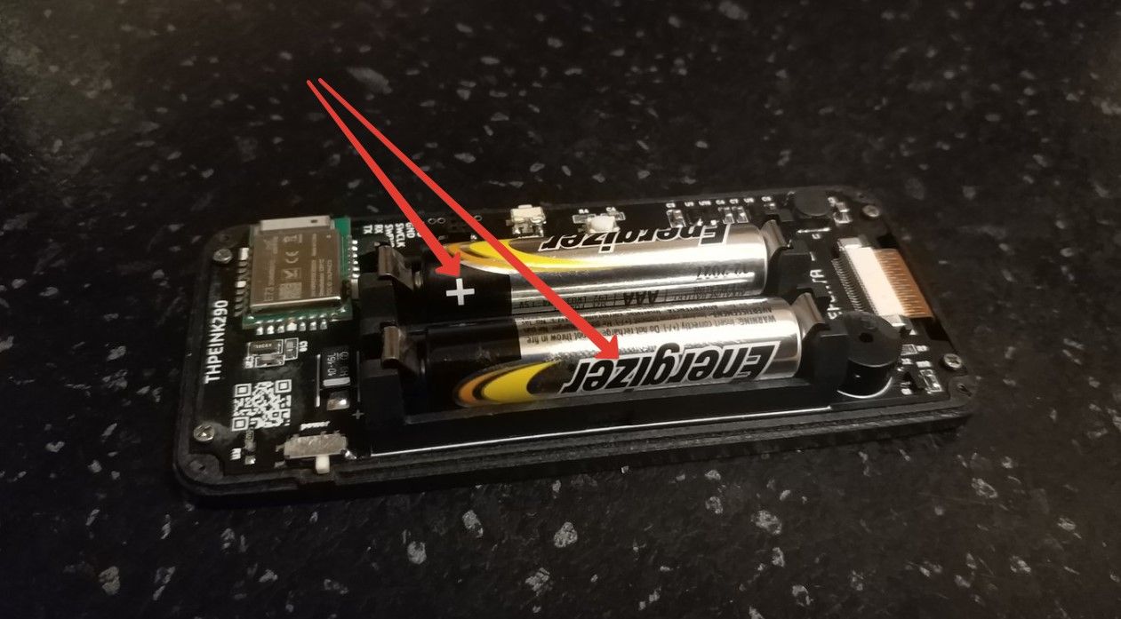
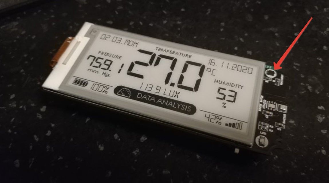
@tiana I have not used it, but it is possible to create different revisions. See https://www.openhardware.io/view/4/EasyNewbie-PCB-for-MySensors#tabs-revisions as an example.
@zeblong, you can generate these from the board files, however i'm leaving this one for @Ivan-Z to discuss with you as this is his device and he knows all details regarding this.
I think you can just set the I2C pins in MyBoardNRF5.h without remapping the pins in MyBoardNRF5.cpp.
Look in MyBoardNRF5.h, under the Wire Interfaces section. Set SDL and SCA to 30 and 31 as appropriate for your board.
Nice project
manufacturers datasheets, RF appnotes etc all mention this, with results for different usecases (like gnd plane size etc). I mentioned it a few times on the forum:
nothing under or near antenna (keep out zone)
their matching circuit, and CE/FCC certif are based on their development boards+their antenna if external, often without enclosure.
there are a very few pcb antennas which are resilient to untuning. ceramic or meandered pcb are usually more compact but less resilient (like when you approach your hand and device suddently has better or worst communication)
once you change any of these parameters (board shape, gnd size, enclosure etc), it breaks FCC, and may need retuning, still you can get useable range.
"ideally" tuning should be done once enclosed for example. manufacturers can't cover all cases.
on my side, I try to follow these rules. and when interested in a design or a device, I check this. Mainly the routing+gnd, antenna choice, keepout zone, and orientation vs my usecase (long range needed or not for example)