Dimmer doesn't appear in devices


  • Hi!

    I just added a led dimmer to my setup
    i used this to build it:
    http://www.mysensors.org/build/dimmer

    the problem is that it doesn't appear in my list 'devices' in domoticz
    in the domoticz log i see this:

    2015-07-13 12:53:36.517 MySensors: Node: 1, Sketch Name: DimmableLED
    2015-07-13 12:53:36.523 MySensors: Node: 1, Sketch Version: 1.1

    someone who can help me with this?


  • Hero Member

    @ThomasDecock did you hardcode the node id?


  • Hero Member

    @ThomasDecock oh and if you can send the sketch and serial monitor outout please?


  • I used this sketch:

    /***
     * This program is free software; you can redistribute it and/or
     * modify it under the terms of the GNU General Public License
     * version 2 as published by the Free Software Foundation.
     * 
     * DESCRIPTION
     * This sketch provides a Dimmable LED Light using PWM and based Henrik Ekblad 
     * <henrik.ekblad@gmail.com> Vera Arduino Sensor project.  
     * Developed by Bruce Lacey, inspired by Hek's MySensor's example sketches.
     * 
     * The circuit uses a MOSFET for Pulse-Wave-Modulation to dim the attached LED or LED strip.  
     * The MOSFET Gate pin is connected to Arduino pin 3 (LED_PIN), the MOSFET Drain pin is connected
     * to the LED negative terminal and the MOSFET Source pin is connected to ground.  
     *
     * This sketch is extensible to support more than one MOSFET/PWM dimmer per circuit.
     *
     * REVISION HISTORY
     * Version 1.0 - February 15, 2014 - Bruce Lacey
     * Version 1.1 - August 13, 2014 - Converted to 1.4 (hek) 
     *
     ***/
    #define SN "DimmableLED"
    #define SV "1.1"
    
    #include <MySensor.h> 
    #include <SPI.h>
    
    #define LED_PIN 3      // Arduino pin attached to MOSFET Gate pin
    #define FADE_DELAY 10  // Delay in ms for each percentage fade up/down (10ms = 1s full-range dim)
    
    MySensor gw;
    
    static int currentLevel = 0;  // Current dim level...
    MyMessage dimmerMsg(0, V_DIMMER);
    MyMessage lightMsg(0, V_LIGHT);
    
    /***
     * Dimmable LED initialization method
     */
    void setup()  
    { 
      Serial.println( SN ); 
      gw.begin( incomingMessage );
      
      // Register the LED Dimmable Light with the gateway
      gw.present( 0, S_DIMMER );
      
      gw.sendSketchInfo(SN, SV);
      // Pull the gateway's current dim level - restore light level upon sendor node power-up
      gw.request( 0, V_DIMMER );
    }
    
    /***
     *  Dimmable LED main processing loop 
     */
    void loop() 
    {
      gw.process();
    }


    void incomingMessage(const MyMessage &message) {
      if (message.type == V_LIGHT || message.type == V_DIMMER) {
        
        //  Retrieve the power or dim level from the incoming request message
        int requestedLevel = atoi( message.data );
        
        // Adjust incoming level if this is a V_LIGHT variable update [0 == off, 1 == on]
        requestedLevel *= ( message.type == V_LIGHT ? 100 : 1 );
        
        // Clip incoming level to valid range of 0 to 100
        requestedLevel = requestedLevel > 100 ? 100 : requestedLevel;
        requestedLevel = requestedLevel < 0   ? 0   : requestedLevel;
        
        Serial.print( "Changing level to " );
        Serial.print( requestedLevel );
        Serial.print( ", from " ); 
        Serial.println( currentLevel );
    
        fadeToLevel( requestedLevel );
        
        // Inform the gateway of the current DimmableLED's SwitchPower1 and LoadLevelStatus value...
        gw.send(lightMsg.set(currentLevel > 0 ? 1 : 0));
    
        // hek comment: Is this really nessesary?
        gw.send( dimmerMsg.set(currentLevel) );
    
        
        }
    }
    
    /***
     *  This method provides a graceful fade up/down effect
     */
    void fadeToLevel( int toLevel ) {
    
      int delta = ( toLevel - currentLevel ) < 0 ? -1 : 1;
      
      while ( currentLevel != toLevel ) {
        currentLevel += delta;
        analogWrite( LED_PIN, (int)(currentLevel / 100. * 255) );
        delay( FADE_DELAY );
      }
    }


    when i open the serial monitor (from the node) i see this: 5àèàÒààð

    i did try with an other script based on that from: GizMoCuz (DimmableLight) (just added one line to control the led's) this is working, but its without the fading and kinda complex :s

    /***
     * This program is free software; you can redistribute it and/or
     * modify it under the terms of the GNU General Public License
     * version 2 as published by the Free Software Foundation.
     * 
     * DESCRIPTION
     * This sketch provides an example how to implement a Dimmable Light 
     * It is pure virtual and it logs messages to the serial output
     * It can be used as a base sketch for actual hardware.
     * Stores the last light state and level in eeprom.
     * 
     * Developed by GizMoCuz (Domoticz)
     *
     * REVISION HISTORY
     * Version 1.0 - January 30, 2015
     *
     ***/
     
    #include <SPI.h>
    #include <MySensor.h>  
    
    #define CHILD_ID_LIGHT 1
    #define LED_PIN 3 
    
    #define EPROM_LIGHT_STATE 1
    #define EPROM_DIMMER_LEVEL 2
    
    #define LIGHT_OFF 0
    #define LIGHT_ON 1
    
    #define SN "Dimable Light"
    #define SV "1.0"
    
    int LastLightState=LIGHT_OFF;
    int LastDimValue=100;
    
    MySensor gw;
    MyMessage lightMsg(CHILD_ID_LIGHT, V_LIGHT);
    MyMessage dimmerMsg(CHILD_ID_LIGHT, V_DIMMER);
    
    void setup()  
    { 
      gw.begin(incomingMessage, AUTO, false);
    
      // Send the Sketch Version Information to the Gateway
      gw.sendSketchInfo(SN, SV);
    
      gw.present(CHILD_ID_LIGHT, S_DIMMER );
    
      //Retreive our last light state from the eprom
      int LightState=gw.loadState(EPROM_LIGHT_STATE); 
      if (LightState<=1) {
        LastLightState=LightState;
        int DimValue=gw.loadState(EPROM_DIMMER_LEVEL); 
        if ((DimValue>0)&&(DimValue<=100)) {
          //There should be no Dim value of 0, this would mean LIGHT_OFF
          LastDimValue=DimValue;
        }
      }
    
      //Here you actualy switch on/off the light with the last known dim level
      SetCurrentState2Hardware();
      
      Serial.println( "Node ready to receive messages..." );  
    }
    
    void loop()      
    {
      //delay(1000);  // Removed by hek 
      // Process incoming messages (like config and light state from controller)
      gw.process();
    }
    
    void incomingMessage(const MyMessage &message)
    {
      if (message.type == V_LIGHT) {
        Serial.println( "V_LIGHT command received..." );
        
        int lstate= atoi( message.data );
        if ((lstate<0)||(lstate>1)) {
          Serial.println( "V_LIGHT data invalid (should be 0/1)" );
          return;
        }
        LastLightState=lstate;
        gw.saveState(EPROM_LIGHT_STATE, LastLightState);
        
        if ((LastLightState==LIGHT_ON)&&(LastDimValue==0)) {
           //In the case that the Light State = On, but the dimmer value is zero,
           //then something (probably the controller) did something wrong,
           //for the Dim value to 100%
          LastDimValue=100;
          gw.saveState(EPROM_DIMMER_LEVEL, LastDimValue);
        }
        
        //When receiving a V_LIGHT command we switch the light between OFF and the last received dimmer value
        //This means if you previously set the lights dimmer value to 50%, and turn the light ON
        //it will do so at 50%
      }
      else if (message.type == V_DIMMER) {
        Serial.println( "V_DIMMER command received..." );  
        int dimvalue= atoi( message.data );
        if ((dimvalue<0)||(dimvalue>100)) {
          Serial.println( "V_DIMMER data invalid (should be 0..100)" );
          return;
        }
        if (dimvalue==0) {
          LastLightState=LIGHT_OFF;
        }
        else {
          LastLightState=LIGHT_ON;
          LastDimValue=dimvalue;
          gw.saveState(EPROM_DIMMER_LEVEL, LastDimValue);
        }
      }
      else {
        Serial.println( "Invalid command received..." );  
        return;
      }
    
      //Here you set the actual light state/level
      SetCurrentState2Hardware();
    }
    
    void SetCurrentState2Hardware()
    {
      if (LastLightState==LIGHT_OFF) {
         Serial.println( "Light state: OFF" );
      }
      else {
         Serial.print( "Light state: ON, Level: " );
         Serial.println( LastDimValue );
      }
    
    analogWrite( LED_PIN, (int)(LastDimValue / 100. * 255) );
      //Send current state to the controller
      SendCurrentState2Controller();
    }
    
    void SendCurrentState2Controller()
    {
      if ((LastLightState==LIGHT_OFF)||(LastDimValue==0)) {
        gw.send(dimmerMsg.set(0));
      }
      else {
        gw.send(dimmerMsg.set(LastDimValue));
      }
    }


  • Admin

    @ThomasDecock said:

    when i open the serial monitor (from the node) i see this: 5àèàÒààð

    Gibberish to the console is usually an indication that the IDE is set to the wrong board (e.g. 5V vs. 3.3V, Nano vs. Mini Pro, etc.) or the console baud in the Arduino IDE. The DimmableLED sketch above has been verified on 1.4.1, Github/Master and Github/development. Double-check your IDE settings and if that doesn't work, ping me and I will try to help you sort it out.

    Thanks,
    Bruce


  • Thanks for the fast reply!

    I use an arduino nano,
    and i see i selected the wrong baud,

    now i get this on the serial monitor:

    sensor started, id 1
    send: 1-1-0-0 s=255,c=0,t=17,pt=0,l=5,st=ok:1.4.1
    send: 1-1-0-0 s=255,c=3,t=6,pt=1,l=1,st=fail:0
    send: 1-1-0-0 s=0,c=0,t=4,pt=0,l=0,st=ok:
    send: 1-1-0-0 s=255,c=3,t=11,pt=0,l=11,st=ok:DimmableLED
    send: 1-1-0-0 s=255,c=3,t=12,pt=0,l=3,st=ok:1.1
    send: 1-1-0-0 s=0,c=2,t=3,pt=0,l=0,st=ok:
    

    in the domoticz log i get this:

    2015-07-13 16:13:15.077 MySensors: Node: 1, Sketch Name: DimmableLED
    2015-07-13 16:13:15.083 MySensors: Node: 1, Sketch Version: 1.1
    

    but the dimmer doesn't appear in the 'device' list from domoticz


  • Admin

    @ThomasDecock said:

    Thanks for the fast reply!

    I use an arduino nano,
    and i see i selected the wrong baud,

    but the dimmer doesn't appear in the 'device' list from domoticz

    Seems like a Domoticoz / gateway issue because the sketch is sending the information to the gateway. Have you added the dimmer to Domoticoz using the Domoticoz UI? Perhaps remove and re-add because you toggled between sketches or force Domoticoz to reload - bottom-line, it could just be a transient state issue that you need to reset once...


  • the way i should add the dimmer to domoticz is with the 'device' page, then i should be able to select the dimmer and add it to my domoticz configuration..

    but the problem with this sketch is that it doesn't appear in domoticz,
    when i use the sketch from GizMoCuz (DimmableLight)

    see here:

    /***
     * This program is free software; you can redistribute it and/or
     * modify it under the terms of the GNU General Public License
     * version 2 as published by the Free Software Foundation.
     * 
     * DESCRIPTION
     * This sketch provides an example how to implement a Dimmable Light 
     * It is pure virtual and it logs messages to the serial output
     * It can be used as a base sketch for actual hardware.
     * Stores the last light state and level in eeprom.
     * 
     * Developed by GizMoCuz (Domoticz)
     *
     * REVISION HISTORY
     * Version 1.0 - January 30, 2015
     *
     ***/
     
    #include <SPI.h>
    #include <MySensor.h>  
    
    #define CHILD_ID_LIGHT 1
    
    #define EPROM_LIGHT_STATE 1
    #define EPROM_DIMMER_LEVEL 2
    
    #define LIGHT_OFF 0
    #define LIGHT_ON 1
    
    #define SN "Dimable Light"
    #define SV "1.0"
    
    int LastLightState=LIGHT_OFF;
    int LastDimValue=100;
    
    MySensor gw;
    MyMessage lightMsg(CHILD_ID_LIGHT, V_LIGHT);
    MyMessage dimmerMsg(CHILD_ID_LIGHT, V_DIMMER);
    
    void setup()  
    { 
      gw.begin(incomingMessage, AUTO, false);
    
      // Send the Sketch Version Information to the Gateway
      gw.sendSketchInfo(SN, SV);
    
      gw.present(CHILD_ID_LIGHT, S_DIMMER );
    
      //Retreive our last light state from the eprom
      int LightState=gw.loadState(EPROM_LIGHT_STATE); 
      if (LightState<=1) {
        LastLightState=LightState;
        int DimValue=gw.loadState(EPROM_DIMMER_LEVEL); 
        if ((DimValue>0)&&(DimValue<=100)) {
          //There should be no Dim value of 0, this would mean LIGHT_OFF
          LastDimValue=DimValue;
        }
      }
    
      //Here you actualy switch on/off the light with the last known dim level
      SetCurrentState2Hardware();
      
      Serial.println( "Node ready to receive messages..." );  
    }
    
    void loop()      
    {
      //delay(1000);  // Removed by hek 
      // Process incoming messages (like config and light state from controller)
      gw.process();
    }
    
    void incomingMessage(const MyMessage &message)
    {
      if (message.type == V_LIGHT) {
        Serial.println( "V_LIGHT command received..." );
        
        int lstate= atoi( message.data );
        if ((lstate<0)||(lstate>1)) {
          Serial.println( "V_LIGHT data invalid (should be 0/1)" );
          return;
        }
        LastLightState=lstate;
        gw.saveState(EPROM_LIGHT_STATE, LastLightState);
        
        if ((LastLightState==LIGHT_ON)&&(LastDimValue==0)) {
           //In the case that the Light State = On, but the dimmer value is zero,
           //then something (probably the controller) did something wrong,
           //for the Dim value to 100%
          LastDimValue=100;
          gw.saveState(EPROM_DIMMER_LEVEL, LastDimValue);
        }
        
        //When receiving a V_LIGHT command we switch the light between OFF and the last received dimmer value
        //This means if you previously set the lights dimmer value to 50%, and turn the light ON
        //it will do so at 50%
      }
      else if (message.type == V_DIMMER) {
        Serial.println( "V_DIMMER command received..." );  
        int dimvalue= atoi( message.data );
        if ((dimvalue<0)||(dimvalue>100)) {
          Serial.println( "V_DIMMER data invalid (should be 0..100)" );
          return;
        }
        if (dimvalue==0) {
          LastLightState=LIGHT_OFF;
        }
        else {
          LastLightState=LIGHT_ON;
          LastDimValue=dimvalue;
          gw.saveState(EPROM_DIMMER_LEVEL, LastDimValue);
        }
      }
      else {
        Serial.println( "Invalid command received..." );  
        return;
      }
    
      //Here you set the actual light state/level
      SetCurrentState2Hardware();
    }
    
    void SetCurrentState2Hardware()
    {
      if (LastLightState==LIGHT_OFF) {
         Serial.println( "Light state: OFF" );
      }
      else {
         Serial.print( "Light state: ON, Level: " );
         Serial.println( LastDimValue );
      }
    
      //Send current state to the controller
      SendCurrentState2Controller();
    }
    
    void SendCurrentState2Controller()
    {
      if ((LastLightState==LIGHT_OFF)||(LastDimValue==0)) {
        gw.send(dimmerMsg.set(0));
      }
      else {
        gw.send(dimmerMsg.set(LastDimValue));
      }
    }


    with this sketc their does appear an dimmer in the 'device' page from domoticz
    (but this is a virtual sketch with no hardware connected to)

    i can add the hardware code from the DimmableLED sketch an inplement it in the sketch from GizMoCuz (DimmableLight).. but I am new at all this, its still kinda hard understanding all the code...
    I also want to add 2 more dimmers to this node (so 3 dimmers in total) but i'am also still figuring out how to do that

    Thanks,
    Thomas


  • Did you enable Domoticz to detect new hardware? It's the default setting but you can turn of the auto inclusion.


  • yes, i did.

    when i hook up a temp sensor and load the temp sketch it appears in my device list
    and it also appears when using the GizMoCuz (DimmableLight) sketch


  • Admin

    @ThomasDecock said:

    yes, i did.

    when i hook up a temp sensor and load the temp sketch it appears in my device list
    and it also appears when using the GizMoCuz (DimmableLight) sketch

    Try moving the gw.sendSketchInfo() before the gw.present() in setup(). Not sure why they are in that order but perhaps the Domoticoz plugin has some order dependence before it assumes a device is valid. If that doesn't work, I will take a look at the Domoticoz plugin to see if I can figure out what is going on...

    Are you using a serial or ethernet gateway?


  • Admin

    @ThomasDecock Also, check this out - http://www.domoticz.com/forum/viewtopic.php?f=6&t=6932

    Which version of Domoticoz and the Domoticoz MySensors plugin are you running?


  • @blacey said:

    @ThomasDecock said:

    yes, i did.

    when i hook up a temp sensor and load the temp sketch it appears in my device list
    and it also appears when using the GizMoCuz (DimmableLight) sketch

    Try moving the gw.sendSketchInfo() before the gw.present() in setup(). Not sure why they are in that order but perhaps the Domoticoz plugin has some order dependence before it assumes a device is valid. If that doesn't work, I will take a look at the Domoticoz plugin to see if I can figure out what is going on...

    Are you using a serial or ethernet gateway?

    I did what you suggested and moved the gw.sendSketchInfo() before the gw.present()
    but nothing changed.

    I am using domoticz version 2.2563 on RPI B+ and a serial gateway. I did take a look in that topic on the domoticz forum and left a reply.

    its really strange that when i use the 'Dimable Light' sketch the dimmer does appear in domoticz but not with the DimmableLED sketch.

    EDIT:
    extra info
    if i first use the ''Dimable Light" sketch so that the dimmer appears in the device list from domoticz and then upload the "DimmableLED" to the node, am i able to control the leds (on pin 3) with the dimmer that was created with the 'dimable light' sketch .

    Kind regards!
    Thomas


  • Hero Member

    Isn't 1 reserved for the gateway?


  • Admin

    @ThomasDecock Glad to hear you got it working! By the way, Domoticoz is up to V2.2657 so you may want to look into updating your version. Let me know if you need help with anything else.

    Cheers,
    Bruce


  • @blacey said:

    @ThomasDecock Glad to hear you got it working! By the way, Domoticoz is up to V2.2657 so you may want to look into updating your version. Let me know if you need help with anything else.

    Cheers,
    Bruce

    Thanks! I thought i was using the beta, but after checking i saw that the 'use beta' option wasn't selected anymore...
    so I just updated and tried once again with the 'DimmableLED' sketch (after deleting the dimmer in my domoticz) and now it does appear in my domoticz device list!!

    now i will attempt to make it from 1 dimmer to 3 dimmers..

    Thanks for the help!


  • Hi!

    I am kind of new here, but I have been trying to build a simple white led dimmer to control with Domoticz.

    So far, I have accomplished to get the radio working, then I built the hardware and finally I tested the dimmer with a simple arduino skecth:

     void setup()
     {
       pinMode( 9, OUTPUT);
       pinMode(10, OUTPUT);
     }
     
     byte b = 0;
    
     void loop()
     {
       analogWrite(9, b);
       analogWrite(10, b);
       delay(100);
       ++b;
     }
    

    And it worked!

    Also, I managed to get the node recognized in Domoticz (after some struggle), but I cannot seem to get Domoticz to actually dim the LED!

    FYI: I used this sketch:

    /**
     * The MySensors Arduino library handles the wireless radio link and protocol
     * between your home built sensors/actuators and HA controller of choice.
     * The sensors forms a self healing radio network with optional repeaters. Each
     * repeater and gateway builds a routing tables in EEPROM which keeps track of the
     * network topology allowing messages to be routed to nodes.
     *
     * Created by Henrik Ekblad <henrik.ekblad@mysensors.org>
     * Copyright (C) 2013-2015 Sensnology AB
     * Full contributor list: https://github.com/mysensors/Arduino/graphs/contributors
     *
     * Documentation: http://www.mysensors.org
     * Support Forum: http://forum.mysensors.org
     *
     * This program is free software; you can redistribute it and/or
     * modify it under the terms of the GNU General Public License
     * version 2 as published by the Free Software Foundation.
     *
     *******************************
     *
     * REVISION HISTORY
     * Version 1.0 - February 15, 2014 - Bruce Lacey
     * Version 1.1 - August 13, 2014 - Converted to 1.4 (hek) 
     *
     * DESCRIPTION
     * This sketch provides a Dimmable LED Light using PWM and based Henrik Ekblad 
     * <henrik.ekblad@gmail.com> Vera Arduino Sensor project.  
     * Developed by Bruce Lacey, inspired by Hek's MySensor's example sketches.
     * 
     * The circuit uses a MOSFET for Pulse-Wave-Modulation to dim the attached LED or LED strip.  
     * The MOSFET Gate pin is connected to Arduino pin 3 (LED_PIN), the MOSFET Drain pin is connected
     * to the LED negative terminal and the MOSFET Source pin is connected to ground.  
     *
     * This sketch is extensible to support more than one MOSFET/PWM dimmer per circuit.
     * http://www.mysensors.org/build/dimmer
     */
    
    #define SN "DimmableLED"
    #define SV "1.1"
    
    #include <MySensor.h> 
    #include <SPI.h>
    
    #define LED_PIN 3      // Arduino pin attached to MOSFET Gate pin
    #define FADE_DELAY 10  // Delay in ms for each percentage fade up/down (10ms = 1s full-range dim)
    
    MySensor gw;
    
    static int currentLevel = 0;  // Current dim level...
    MyMessage dimmerMsg(0, V_DIMMER);
    MyMessage lightMsg(0, V_LIGHT);
    
    
    /***
     * Dimmable LED initialization method
     */
    void setup()  
    { 
      Serial.println( SN ); 
      gw.begin( incomingMessage );
      
      // Register the LED Dimmable Light with the gateway
      gw.present( 0, S_DIMMER );
      
      gw.sendSketchInfo(SN, SV);
      // Pull the gateway's current dim level - restore light level upon sendor node power-up
      gw.request( 0, V_DIMMER );
    }
    
    /***
     *  Dimmable LED main processing loop 
     */
    void loop() 
    {
      gw.process();
    }


    void incomingMessage(const MyMessage &message) {
      if (message.type == V_LIGHT || message.type == V_DIMMER) {
        
        //  Retrieve the power or dim level from the incoming request message
        int requestedLevel = atoi( message.data );
        
        // Adjust incoming level if this is a V_LIGHT variable update [0 == off, 1 == on]
        requestedLevel *= ( message.type == V_LIGHT ? 100 : 1 );
        
        // Clip incoming level to valid range of 0 to 100
        requestedLevel = requestedLevel > 100 ? 100 : requestedLevel;
        requestedLevel = requestedLevel < 0   ? 0   : requestedLevel;
        
        Serial.print( "Changing level to " );
        Serial.print( requestedLevel );
        Serial.print( ", from " ); 
        Serial.println( currentLevel );
    
        fadeToLevel( requestedLevel );
        
        // Inform the gateway of the current DimmableLED's SwitchPower1 and LoadLevelStatus value...
        gw.send(lightMsg.set(currentLevel > 0 ? 1 : 0));
    
        // hek comment: Is this really nessesary?
        gw.send( dimmerMsg.set(currentLevel) );
    
        
        }
    }
    
    /***
     *  This method provides a graceful fade up/down effect
     */
    void fadeToLevel( int toLevel ) {
    
      int delta = ( toLevel - currentLevel ) < 0 ? -1 : 1;
      
      while ( currentLevel != toLevel ) {
        currentLevel += delta;
        analogWrite( LED_PIN, (int)(currentLevel / 100. * 255) );
        delay( FADE_DELAY );
      }
    }
    

    Can somebody help me please?

    I am using a 3.3v Arduino Mini Pro clone, a IRF540 MOSFET and a 12v power supply.

    Thanks for your help!

    PS: amazing project!


  • Hero Member

    @andrezibaia If you have the serial monitor hooked up to the sensor (dimmer), do you see the "Changing level to " output in the serial log?

    Cheers
    Al


  • Hi @Sparkman!

    No, the sensor does not get any input.

    This is all I get in the serial monitor:

    send: 55-55-0-0 s=255,c=0,t=17,pt=0,l=3,sg=0,st=ok:1.5
    send: 55-55-0-0 s=255,c=3,t=6,pt=1,l=1,sg=0,st=ok:0
    sensor started, id=55, parent=0, distance=0
    send: 55-55-0-0 s=0,c=0,t=4,pt=0,l=0,sg=0,st=ok:
    send: 55-55-0-0 s=255,c=3,t=11,pt=0,l=11,sg=0,st=ok:DimmableLED
    send: 55-55-0-0 s=255,c=3,t=12,pt=0,l=3,sg=0,st=ok:1.1
    send: 55-55-0-0 s=0,c=2,t=3,pt=0,l=0,sg=0,st=ok:
    

    Thanks for the ultra-fast reply!


  • Hero Member

    @andrezibaia NP. Maybe add a println in the incomingMessage function:

    void incomingMessage(const MyMessage &message) {
     Serial.println( message.type );
      if (message.type == V_LIGHT || message.type == V_DIMMER) {
    

    and then send a command from Domoticz and see what the serial log shows when you do that.

    Cheers
    Al


  • @Sparkman, nothing happens...

    No message at all in the serial monitor.


  • Hero Member

    @andrezibaia To rule out an issue with Domoticz, do you have the ability to hookup the gateway to MYSController? Might be worth a try to see what happens with it.

    Cheers
    Al


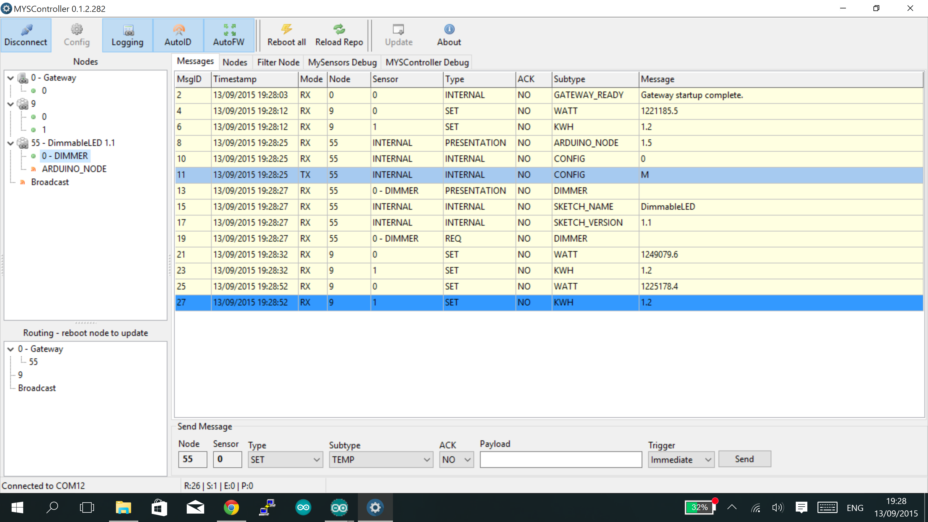
  • Yes, sure. Just did that.

    Here's what I have:

    upload-d51ca5cc-04b6-4516-9878-ce26ecbe57ed

    What should I do now?

    Cheers!


  • Hero Member

    @andrezibaia Should be able to send a message to the node using the "Send Message" portion on the bottom of the screen.

    Cheers
    Al


  • Sure. What should I write in the payload section?

    I tried this, but nothing happened.

    upload-2fe2e7d5-4492-44df-b83d-e35436ce14b3

    I'm sorry for all the "noobness", I am still trying to learn all this...


  • Hero Member

    @andrezibaia Looks correct. Anything in the serial monitor of the dimmer? Try the light subtype as well and send a 0 or a 1. What does the MYSController log show when you do this?

    Cheers
    Al


  • Nothing at all in the node serial monitor...

    The log from MYSController shows this:

    13/09/2015 19:53:01	TX	55;255;3;0;6;M
    13/09/2015 19:53:01	RX	55;255;3;0;6;0
    13/09/2015 19:53:04	RX	0;0;3;0;9;read: 55-55-0 s=0,c=0,t=4,pt=0,l=0,sg=0:
    13/09/2015 19:53:04	DEBUG	Update child id=0, type=DIMMER
    13/09/2015 19:53:04	RX	55;0;0;0;4;
    13/09/2015 19:53:04	RX	0;0;3;0;9;read: 55-55-0 s=255,c=3,t=11,pt=0,l=11,sg=0:DimmableLED
    13/09/2015 19:53:04	RX	55;255;3;0;11;DimmableLED
    13/09/2015 19:53:04	RX	0;0;3;0;9;read: 55-55-0 s=255,c=3,t=12,pt=0,l=3,sg=0:1.1
    13/09/2015 19:53:04	RX	55;255;3;0;12;1.1
    13/09/2015 19:53:04	RX	0;0;3;0;9;read: 55-55-0 s=0,c=2,t=3,pt=0,l=0,sg=0:
    13/09/2015 19:53:04	RX	55;0;2;0;3;
    13/09/2015 19:53:12	TX	55;0;1;0;3;50
    13/09/2015 19:53:46	RX	0;0;3;0;9;read: 55-55-0 s=255,c=0,t=17,pt=0,l=3,sg=0:1.5
    13/09/2015 19:53:46	DEBUG	Update child id=255, type=ARDUINO_NODE
    13/09/2015 19:53:46	RX	55;255;0;0;17;1.5
    13/09/2015 19:53:46	RX	0;0;3;0;9;read: 55-55-0 s=255,c=3,t=6,pt=1,l=1,sg=0:0
    13/09/2015 19:53:46	TX	55;255;3;0;6;M
    13/09/2015 19:53:46	RX	55;255;3;0;6;0
    13/09/2015 19:53:48	RX	0;0;3;0;9;read: 55-55-0 s=0,c=0,t=4,pt=0,l=0,sg=0:
    13/09/2015 19:53:48	DEBUG	Update child id=0, type=DIMMER
    13/09/2015 19:53:48	RX	55;0;0;0;4;
    13/09/2015 19:53:48	RX	0;0;3;0;9;read: 55-55-0 s=255,c=3,t=11,pt=0,l=11,sg=0:DimmableLED
    13/09/2015 19:53:48	RX	55;255;3;0;11;DimmableLED
    13/09/2015 19:53:48	RX	0;0;3;0;9;read: 55-55-0 s=255,c=3,t=12,pt=0,l=3,sg=0:1.1
    13/09/2015 19:53:48	RX	55;255;3;0;12;1.1
    13/09/2015 19:53:48	RX	0;0;3;0;9;read: 55-55-0 s=0,c=2,t=3,pt=0,l=0,sg=0:
    13/09/2015 19:53:48	RX	55;0;2;0;3;
    13/09/2015 19:53:56	TX	55;0;1;0;3;50
    13/09/2015 19:54:16	TX	55;0;1;0;2;50
    13/09/2015 19:55:02	TX	55;0;1;0;2;50
    

  • Hero Member

    @andrezibaia said:

    13/09/2015 19:53:56 TX 55;0;1;0;3;50
    13/09/2015 19:54:16 TX 55;0;1;0;2;50
    13/09/2015 19:55:02 TX 55;0;1;0;2;50

    The last 3 lines show you sending 50 to the dimmer device first (3) and then twice to the light device (2). The light device should only respond to a 0 or a 1. Have you tried sending that?

    Cheers
    Al


  • Yes, I tried that as well. Nothing happened.

    In the meantime, the serial monitor from the node shows only this and nothing else:

    send: 55-55-0-0 s=255,c=0,t=17,pt=0,l=3,sg=0,st=ok:1.5
    send: 55-55-0-0 s=255,c=3,t=6,pt=1,l=1,sg=0,st=ok:0
    sensor started, id=55, parent=0, distance=0
    send: 55-55-0-0 s=0,c=0,t=4,pt=0,l=0,sg=0,st=ok:
    send: 55-55-0-0 s=255,c=3,t=11,pt=0,l=11,sg=0,st=ok:DimmableLED
    send: 55-55-0-0 s=255,c=3,t=12,pt=0,l=3,sg=0,st=ok:1.1
    send: 55-55-0-0 s=0,c=2,t=3,pt=0,l=0,sg=0,st=ok:
    

    Is it perhaps a problem with the radio? It only sends and does not receive?

    I tried different NRF24L01+ chips, but the problem remains...

    I even tried to feed the NRF chip through a 3.3v regulator, but nothing happens...


  • Hero Member

    @andrezibaia said:

    Is it perhaps a problem with the radio? It only sends and does not receive?

    It's possible, but none of the logs indicate a communications issue. Maybe @blacey who wrote the sketch or @hek have some other ideas.

    Cheers
    Al


  • @Sparkman Thanks a lot for all your time and effort!

    Cheers!


  • @Sparkman, after a lot of days of despair, I found the problem!

    My gateway was built on a 3.3v Arduino Mini Pro. As soon as I set it up on a 5V one (I did not even need a power regulator for the radio, because I used one of those Sparkfun ones with an antenna.

    Now it's all kicking ass! 💃

    Thanks again, man!


  • Hero Member

    @andrezibaia You're welcome and glad to hear you got it resolved.

    Cheers
    Al


Log in to reply
 

Suggested Topics

  • 5
  • 4
  • 1
  • 3
  • 2
  • 5

28
Online

11.2k
Users

11.1k
Topics

112.5k
Posts