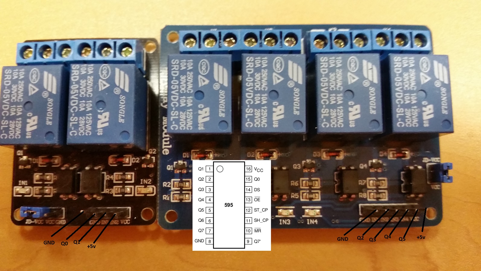
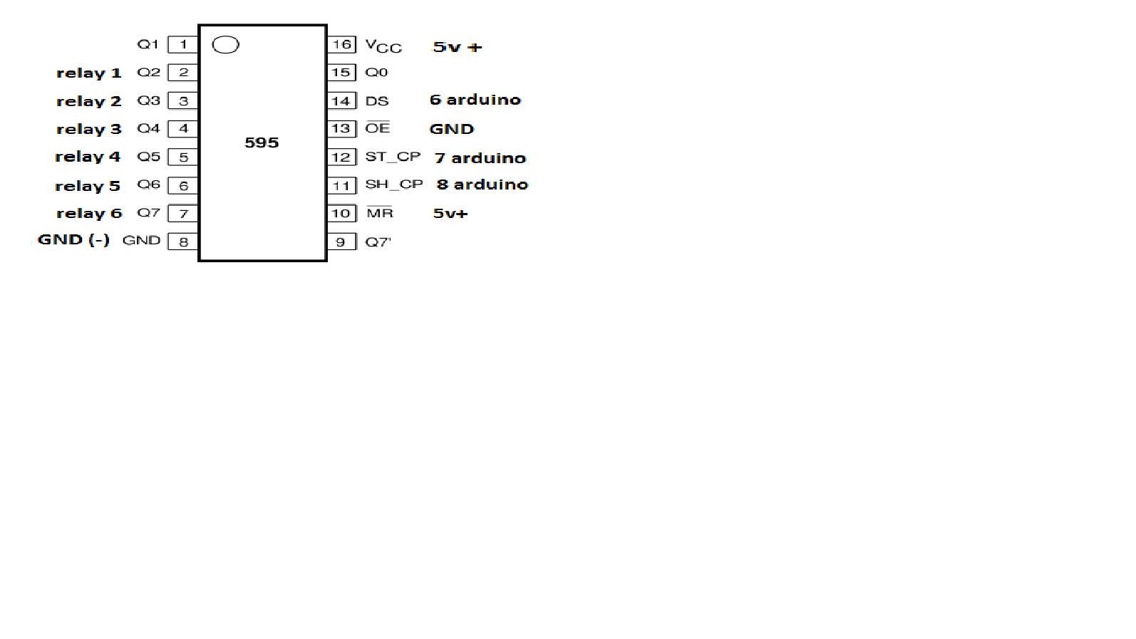
RelayWithButtonActuator (6 channel)


  • PARTS LIST:

    Relays (6 channel)
    NRF24L01 Radio
    Arduino Pro Mini
    Push button (6)
    Shift Register (SN74HC595)

    Hello. Help make this project. I need to control 6 groups of 6 through the controller and buttons that are on the device. I neselen writing sketch. what people can help.
    needs a sketch and a description of how to collect it. I need to control the lighting in the street like a phone and pressing locally on the device itself.
    willing to pay for it, if necessary.


  • устройство.jpg платка в сборе.jpg платка травление.jpg


  • Contest Winner

    @vampircik i can help writing a sketch, but what exactly do you want to achieve .

    • Just a 6 times on/off button operated relays?
    • and why adding the shift register the Pro mini should have enough I/O pins?

    But can you send met the exact wiring diagram, than i can give it a try.


  • you did not understand. in the scheme will be 6 switches and relays 6. all these controls one Arduino.

    @BartE said:

    i can help writing a sketch, but what exactly do you want to achieve .

    Just a 6 times on/off button operated relays?
    and why adding the shift register the Pro mini should have enough I/O pins?
    But can you send met the exact wiring diagram, than i can give it a try.


  • arduino.png


  • нажали кнопку, включилось реле, потом выключили через телефон это реле. и так в любой последовательности.


  • arduino.png


  • Contest Winner

    @vampircik this code snippet should work.

    The switch 1 till 6 should be connected to pin A0, A1, A2, A3, 4 and 5 and should connect to ground.

    The SN74HC595 should be connected with:

    • pin 14 (DS) to Arduino pin 6

    • pin 12 (LATCH/ST_CP) to Arduino pin 7

    • pin 8 (CLK/SH_CP) to Arduino pin 11

    • pin 16 (Vcc) and pin 10 (MR) to + 5 volt

    • pin 8 (GND) and pin 13 (OE) to ground

    • relay 1-6 to pin 15 (Q0), 1 (Q1), 2 (Q2), 3 (Q3), 4 (Q4) and 5 (Q4) the other relay pins connected to ground
      (note 18/1: fixed pin number error as posted below)

    /**
     * The MySensors Arduino library handles the wireless radio link and protocol
     * between your home built sensors/actuators and HA controller of choice.
     * The sensors forms a self healing radio network with optional repeaters. Each
     * repeater and gateway builds a routing tables in EEPROM which keeps track of the
     * network topology allowing messages to be routed to nodes.
     *
     * Created by Henrik Ekblad <henrik.ekblad@mysensors.org>
     * Copyright (C) 2013-2015 Sensnology AB
     * Full contributor list: https://github.com/mysensors/Arduino/graphs/contributors
     *
     * Documentation: http://www.mysensors.org
     * Support Forum: http://forum.mysensors.org
     *
     * This program is free software; you can redistribute it and/or
     * modify it under the terms of the GNU General Public License
     * version 2 as published by the Free Software Foundation.
     *
     *******************************
     *
     * REVISION HISTORY
     * Version 1.0 - Henrik Ekblad
     * Version 1.1 - Bart Eversdijk - 6 switch version with Shift Register (SN74HC595)
     * 
     * DESCRIPTION
     * Example sketch showing how to control physical relays. 
     * This example will remember relay state after power failure.
     * http://www.mysensors.org/build/relay
     */ 
    
    #include <MySigningNone.h>
    #include <MyTransportNRF24.h>
    #include <MyTransportRFM69.h>
    #include <MyHwATMega328.h>
    #include <MySensor.h>
    #include <Bounce2.h>
    #include <SPI.h>
    #define MYS_INIT_DELAY 500
    
    #define PIN_SR_DATA      6  // shift register data pin   -- data out - 74HC595 (DS) pin 14 
    #define PIN_SR_LATCH     7  // shift register latch pin  -- data out - 74HC595 (RCLK) pin 12 
    #define PIN_SR_CLOCK     8  // shift register clock pin  -- data out - 74HC595 (CLK) pin 11
    
    struct SWITCHES {
        byte      currentStatus; 
        int       SwitchPin;   // To which Arduino pin this switch is connected
        Bounce    debouncer;
        MyMessage switchMsg;
    };
    
    SWITCHES switches[] = {
              {0, A0, Bounce(), MyMessage(0, V_LIGHT)},    // Arduino pin A0
              {0, A1, Bounce(), MyMessage(1, V_LIGHT)},    // Arduino pin A1
              {0, A2, Bounce(), MyMessage(2, V_LIGHT)},    // Arduino pin A2
              {0, A3, Bounce(), MyMessage(3, V_LIGHT)},    // Arduino pin A3
              {0,  4, Bounce(), MyMessage(4, V_LIGHT)},    // Arduino pin D4
              {0,  5, Bounce(), MyMessage(5, V_LIGHT)}     // Arduino pin D5
            };
    #define MAXSWITCHES (sizeof(switches)/sizeof(SWITCHES))
    
    
    // NRFRF24L01 radio driver (set low transmit power by default) 
    MyTransportNRF24 radio(RF24_CE_PIN, RF24_CS_PIN, RF24_PA_LEVEL_GW);  
    //MyTransportRFM69 radio;
    // Message signing driver (none default)
    //MySigningNone signer;
    // Select AtMega328 hardware profile
    MyHwATMega328 hw;
    // Construct MySensors library
    MySensor gw(radio, hw);
    
    void setup()  
    {   
        // Initialize library and add callback for incoming messages
        gw.begin(incomingMessage, AUTO, true);
        
        // Send the sketch version information to the gateway and Controller
        gw.sendSketchInfo("RelaySix", "1.1");
    
        // Fetch relay status
        for (int id=0; id < MAXSWITCHES; id++) {
           pinMode(switches[id].SwitchPin, INPUT);
           // Activate internal pull-up
           digitalWrite(switches[id].SwitchPin, HIGH); 
            
           gw.present( id, S_LIGHT );
           delay( MYS_INIT_DELAY );
    
           // Pull the gateway's current dim level - restore light level upon sendor node power-up
           gw.request( id, V_STATUS );
           delay( MYS_INIT_DELAY );
           
           // After setting up the button, setup debouncer
           switches[id].debouncer.attach(switches[id].SwitchPin);
           switches[id].debouncer.interval(5);
        }
        
        // Set shift register pins
        pinMode(PIN_SR_DATA,     OUTPUT);
        pinMode(PIN_SR_LATCH,    OUTPUT);
        pinMode(PIN_SR_CLOCK,    OUTPUT);
        digitalWrite(PIN_SR_LATCH, HIGH);
        
        // Switch off all relays
        sendRelayValues();
    }
    
    
    void loop() 
    {
        // Alway process incoming messages whenever possible
        gw.process();
      
        for (byte id = 0; id < MAXSWITCHES; id++) {
            // Button change detected
            if (switches[id].debouncer.update()) {
               Serial.print (F("Switch #"));
               Serial.print (id);
               Serial.print (F(" to "));
               Serial.println (switches[id].debouncer.read());
               
               // Button release detected toggle relay
               if (!switches[id].debouncer.read()) {
                 // Toggle relay status
                 switches[id].currentStatus = (switches[id].currentStatus ? 0 : 1);
                 
                 // Set the actual relay status (all 6 at once)
                 sendRelayValues();
                 
                 // Inform the gateway of the current switch status...
                 gw.send(switches[id].switchMsg.set(switches[id].currentStatus));
               }
            }
        }
    }
    
    void sendRelayValues() {
        // Actually send the valve bits
        digitalWrite(PIN_SR_LATCH, LOW);
    
        // Shift out all station bit values
        // from the highest bit to the lowest
        for(int id = 0; id < 8; id++)  {
            digitalWrite(PIN_SR_CLOCK, LOW);
            if (id < MAXSWITCHES) {
              digitalWrite(PIN_SR_DATA, (switches[id].currentStatus > 0 ? HIGH : LOW));
            } else {
              digitalWrite(PIN_SR_DATA, LOW);
            }
            digitalWrite(PIN_SR_CLOCK, HIGH);          
        }
        // Set new data active
        digitalWrite(PIN_SR_LATCH, HIGH);
    }
    
    void incomingMessage(const MyMessage &message) {
      if (message.isAck()) {
         Serial.println("This is an ack from gateway");
      }
      
      if (message.type == V_LIGHT) {
         byte id = (message.sensor % MAXSWITCHES);
    
         // Store new value
         switches[id].currentStatus = message.getBool() ? 1 : 0;
         
         // Set the actual relay status (all 6 at once)
         sendRelayValues();
         
         // Inform the gateway of the current switch status...
         gw.send(switches[id].switchMsg.set(switches[id].currentStatus));
               
         // Write some debug info
         Serial.print("Incoming change for sensor:");
         Serial.print(message.sensor);
         Serial.print(", New status: ");
         Serial.println(message.getBool());
       } 
    }


    About your "willing to pay" remark in the original post, just make a donation to the MySensors project


  • Thank you. Today I will try. according to the results let you know.


  • @BartE said:

    pin 8 (CLK) to Arduino pin 11

    pin 16 (Vcc) to + 5 volt

    pin 8 (GND) to ground

    ?
    Arduino pin 11 = (GND) ?


  • pin 8 (CLK) to Arduino pin 11
    pin 8 (GND) to ground

    contrary


  • pin 14 (DS) to Arduino pin 6

    relay 1-6 to pin 14 (Qa)

    contraryмикросхема.png


  • This post is deleted!


  • pin 14 (DS) to Arduino pin 6
    pin 8 (CLK) to Arduino pin 11
    pin 8 (GND) to ground
    relay 1-6 to pin 14 (Qa),
    микрик.png


  • Hero Member

    Maybe it should be like this:

    relay 1-6 to pin 15 (Q0), 1 (Q1), 2 (Q2), 3 (Q3), 4 (Q4) and 5 (Q5)


  • pin 8 (CLK) to Arduino pin 11

    and with the contact what to do?


  • Arduino pin 11 = MOSI NRF24


  • wiring.png
    it seems to me must be so connected. except for the screen?


  • Hero Member

    @vampircik said:

    pin 8 (CLK) to Arduino pin 11

    and with the contact what to do?

    Looking att the code @BartE posted it seems like it was supposed to be

    pin 11 (CLK) to Arduino pin 8


  • ok try. ...............


  • Hero Member

    So the correct instructions should have been:

    pin 14 (DS) to Arduino pin 6
    pin 12 (RCLK) to Arduino pin 7
    pin 11 (CLK) to Arduino pin 8
    pin 16 (Vcc) to + 5 volt
    pin 8 (GND) to ground

    relay 1-6 to pin 15 (Q0), 1 (Q1), 2 (Q2), 3 (Q3), 4 (Q4) and 5 (Q5) the other relay pins connected to ground

    Please @BartE correct me if I'm wrong since I have no personal experience from this kind of setup.


  • collected is not working. the controller displays the switch, but it does not control the Arduino.


  • includes buttons, it is displayed on the controller, with only relay nothing happens


  • так.jpg


  • Hero Member

    Do you get anything in the serial monitor for your Relay Node?


  • send: 18-18-0-0 s=255,c=0,t=18,pt=0,l=3,sg=0,st=ok:1.5
    send: 18-18-0-0 s=255,c=3,t=6,pt=1,l=1,sg=0,st=ok:0
    read: 0-0-18 s=255,c=3,t=6,pt=0,l=1,sg=0:M
    repeater started, id=18, parent=0, distance=1
    send: 18-18-0-0 s=255,c=3,t=11,pt=0,l=8,sg=0,st=ok:RelaySix
    send: 18-18-0-0 s=255,c=3,t=12,pt=0,l=3,sg=0,st=ok:1.1
    send: 18-18-0-0 s=0,c=0,t=3,pt=0,l=0,sg=0,st=ok:
    send: 18-18-0-0 s=0,c=2,t=2,pt=0,l=0,sg=0,st=ok:
    send: 18-18-0-0 s=1,c=0,t=3,pt=0,l=0,sg=0,st=ok:
    send: 18-18-0-0 s=1,c=2,t=2,pt=0,l=0,sg=0,st=ok:
    send: 18-18-0-0 s=2,c=0,t=3,pt=0,l=0,sg=0,st=ok:
    send: 18-18-0-0 s=2,c=2,t=2,pt=0,l=0,sg=0,st=ok:
    send: 18-18-0-0 s=3,c=0,t=3,pt=0,l=0,sg=0,st=fail:
    send: 18-18-0-0 s=3,c=2,t=2,pt=0,l=0,sg=0,st=fail:
    send: 18-18-0-0 s=4,c=0,t=3,pt=0,l=0,sg=0,st=fail:
    send: 18-18-0-0 s=4,c=2,t=2,pt=0,l=0,sg=0,st=fail:
    send: 18-18-0-0 s=5,c=0,t=3,pt=0,l=0,sg=0,st=fail:
    send: 18-18-0-0 s=5,c=2,t=2,pt=0,l=0,sg=0,st=fail:
    find parent
    send: 18-18-255-255 s=255,c=3,t=7,pt=0,l=0,sg=0,st=bc:
    read: 0-0-18 s=0,c=1,t=2,pt=0,l=1,sg=0:0
    send: 18-18-0-0 s=0,c=1,t=2,pt=1,l=1,sg=0,st=ok:0
    Incoming change for sensor:0, New status: 0
    read: 0-0-18 s=1,c=1,t=2,pt=0,l=1,sg=0:0
    send: 18-18-0-0 s=1,c=1,t=2,pt=1,l=1,sg=0,st=ok:0
    Incoming change for sensor:1, New status: 0
    read: 0-0-18 s=2,c=1,t=2,pt=0,l=1,sg=0:0
    send: 18-18-0-0 s=2,c=1,t=2,pt=1,l=1,sg=0,st=ok:0
    Incoming change for sensor:2, New status: 0
    read: 0-0-18 s=255,c=3,t=8,pt=1,l=1,sg=0:0
    parent=0, d=1
    Switch #1 to 1
    Switch #2 to 1
    Switch #3 to 1
    Switch #4 to 1
    Switch #5 to 1
    Switch #1 to 0
    send: 18-18-0-0 s=1,c=1,t=2,pt=1,l=1,sg=0,st=ok:1
    Switch #1 to 1
    Switch #2 to 0
    send: 18-18-0-0 s=2,c=1,t=2,pt=1,l=1,sg=0,st=ok:1
    Switch #2 to 1
    Switch #0 to 1
    Switch #0 to 0
    send: 18-18-0-0 s=0,c=1,t=2,pt=1,l=1,sg=0,st=ok:1
    Switch #3 to 0
    send: 18-18-0-0 s=3,c=1,t=2,pt=1,l=1,sg=0,st=ok:1
    Switch #3 to 1
    Switch #4 to 0
    send: 18-18-0-0 s=4,c=1,t=2,pt=1,l=1,sg=0,st=ok:1
    Switch #4 to 1
    Switch #5 to 0
    send: 18-18-0-0 s=5,c=1,t=2,pt=1,l=1,sg=0,st=ok:1
    Switch #5 to 1
    Switch #4 to 0
    send: 18-18-0-0 s=4,c=1,t=2,pt=1,l=1,sg=0,st=ok:1
    Switch #4 to 1
    Switch #4 to 0
    send: 18-18-0-0 s=4,c=1,t=2,pt=1,l=1,sg=0,st=ok:1
    Switch #4 to 1
    Switch #4 to 0
    send: 18-18-0-0 s=4,c=1,t=2,pt=1,l=1,sg=0,st=ok:1
    Switch #4 to 1
    Switch #4 to 0
    send: 18-18-0-0 s=4,c=1,t=2,pt=1,l=1,sg=0,st=ok:1
    Switch #4 to 1
    Switch #5 to 0
    send: 18-18-0-0 s=5,c=1,t=2,pt=1,l=1,sg=0,st=ok:1
    Switch #5 to 1
    Switch #5 to 0
    send: 18-18-0-0 s=5,c=1,t=2,pt=1,l=1,sg=0,st=ok:1
    Switch #5 to 1
    Switch #4 to 0
    send: 18-18-0-0 s=4,c=1,t=2,pt=1,l=1,sg=0,st=ok:1
    Switch #4 to 1
    Switch #5 to 0
    send: 18-18-0-0 s=5,c=1,t=2,pt=1,l=1,sg=0,st=ok:1
    Switch #5 to 1
    Switch #3 to 0
    send: 18-18-0-0 s=3,c=1,t=2,pt=1,l=1,sg=0,st=ok:1
    Switch #3 to 1
    Switch #3 to 0
    send: 18-18-0-0 s=3,c=1,t=2,pt=1,l=1,sg=0,st=ok:1
    Switch #3 to 1
    Switch #3 to 0
    send: 18-18-0-0 s=3,c=1,t=2,pt=1,l=1,sg=0,st=ok:1
    Switch #3 to 1
    Switch #4 to 0
    send: 18-18-0-0 s=4,c=1,t=2,pt=1,l=1,sg=0,st=ok:1
    Switch #4 to 1
    Switch #4 to 0
    send: 18-18-0-0 s=4,c=1,t=2,pt=1,l=1,sg=0,st=ok:1
    Switch #4 to 1
    Switch #4 to 0
    send: 18-18-0-0 s=4,c=1,t=2,pt=1,l=1,sg=0,st=ok:1
    Switch #4 to 1
    Switch #5 to 0
    send: 18-18-0-0 s=5,c=1,t=2,pt=1,l=1,sg=0,st=ok:1
    Switch #5 to 1
    Switch #0 to 1
    Switch #0 to 0
    send: 18-18-0-0 s=0,c=1,t=2,pt=1,l=1,sg=0,st=ok:1
    Switch #0 to 1
    Switch #0 to 0
    send: 18-18-0-0 s=0,c=1,t=2,pt=1,l=1,sg=0,st=ok:1
    Switch #2 to 0
    send: 18-18-0-0 s=2,c=1,t=2,pt=1,l=1,sg=0,st=ok:1
    Switch #2 to 1
    Switch #2 to 0
    send: 18-18-0-0 s=2,c=1,t=2,pt=1,l=1,sg=0,st=ok:1
    Switch #2 to 1
    Switch #1 to 0
    send: 18-18-0-0 s=1,c=1,t=2,pt=1,l=1,sg=0,st=ok:1
    Switch #1 to 1
    Switch #1 to 0
    send: 18-18-0-0 s=1,c=1,t=2,pt=1,l=1,sg=0,st=ok:1
    Switch #1 to 1


  • 11211.png

    this is what I have now happened. includes a button, turn on the relay, reclosing button, there is no result


  • individual libraries should be shipped to the chip?


  • This post is deleted!

  • Contest Winner

    @vampircik i see that with some help from korttoma you manage to find the correct pins setting. @korttoma thx for your help.
    korttoma is right about the pin 11, i should have added this link with more background info

    The sketch is designed for push buttons and not for toggle switches and will respond when releasing a button press.
    In your movie i see that switching on and off via MySensors (mouse clicks) works but the button presses not (always) only switching off.

    I found an error in my sketch on line 131

    // Store new switch value
    switches[id].currentStatus = (switchValue ? 0 : 1);


    the correct line should be

    // Toggle relay status
    switches[id].currentStatus = (switches[id].currentStatus ? 0 : 1);


    note: I've updated the sketch in the original post as well


  • BartE Thank you. everything worked.


  • I made my monetary investment. though not particularly large


  • Connect the power supply to the relay which should be governed by the device stops working


Log in to reply
 

Suggested Topics

  • 8
  • 90
  • 3
  • 2
  • 1
  • 2

23
Online

11.2k
Users

11.1k
Topics

112.5k
Posts