My look at a cheap 12V power supply
-
Summary
This post shares my own non-professional evaluation of the 230Vac to 12Vdc cheap Chinese converter module (aka Switched Mode Power Supply, SMPS) called YS-12V400-B. It's now rather rare, but instead replaced by the very simmilar HX-12V400X which is found easily on Aliexpress by searching "12V 400mA power supply").
This is not a thorough test. I've looked documentation, load- and temperature- and startup characteristics and did some simple noise filter tests.
I will not give a straight answer to your question "is it safe?", instead I hope to provide information enough for you to draw your own conclusions.
Introduction
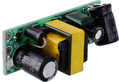
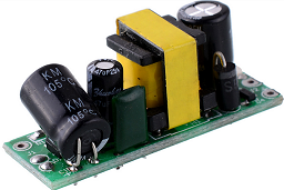
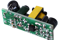
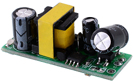
I first saw this module from @axillents post in another thread . I bought a batch almost a year ago , but haven't had the time to look at it until now. Now, a quick look at Ali tells me that it has become rather popular at a few sellers, but there's still no reviews to find. Some user comments I found here .There is a new variant of the YS-12V400-B called HX-12V400X where the first (of few?) differences I can see from photos is that a clear blue (XY-grade?) high voltage capacitor has replaced a flat dark green one. Also there's an anti-creepage hole removed near mains input, where a pad has been changed instead. The HX-12V400X seems to be the most common one available on Ali and should probably be better to buy. The one I bought is gone of course. Here's one of few old ones, though.
Like everybody else, I'm looking for a small supply for my projects. The HLK-PM01 is bulky and I don't see a great value of the enclosure when the bare 230V pins are still there. Also, I care about safety and would not feel comfortable with this kind of unknown quality supply in a class III appliance device where secondary side is touchable. I'd prefer a metal case (class I) for safety earthing and fire protection, but it's not always very economical or practical so I then put my trust in good fuses, insulation (class II) and protective functions.
Some reasons for me to favour 12V in front of 3.3V and 5V are:
- A strive to standardize parts, reuse and keep my assortment of parts as lean as possible.
- Easily converted to 5V or 3.3V with linear regulator where the extra converter's power supply ripple rejection (PSRR) is desired.
- I don't mind the small extra loss or heat due to 5V or 3.3V conversion.
- Flexible in respect of component selection and circuit design. Particularly when dealing with electromechanics like relays and servos.
- Preferable if one wish to distribute power further without to much loss and voltage drop.
- Less current and smaller components.
- Works with Arduino Pro Mini internal regulator. (Note that some APM clones can't handle 12V.)
Since the HLK-PM01 has become our reference device after the famous lygte-info.dk review , I've been thinking that some kind of testing and closer look needs to be done before using ANY kind of Chinese SMPS. I may not have all equipment or skill, but with a small effort a lot can be done. At least to reassure myself that the device is useable (or not). Still, I don't consider anything but certified products as "safe".
Documentation
Official specifications are hard to find and very limited as usual when it comes to these cheap Chinese products:
Dimensions: :4 x1.5 x 1.8cm
Input voltage:AC 90V~240V 50/60HZ
Output voltage:DC 12V (±0.2V)
Output Current: 400mA
Output power: 4.8W
90V~240V AC Input,Constant 12V DC Output ,Ultra small,Precision
Application: the power adapter,industrial equipment,microcontroller,LED lighting power supply, etc
AC input:Does not distinguish between live line and null line.
Protection functions:YES
Shortage Protection:YES
Temperature protection:YES
Overcurrent protection:YESA look through the magnifier reveals the controller IC name "THX208", which then provided a pretty good datasheet . (Of course you might need a translation tool, but after that it's very readable). It turns out that the power supply module we're studying is designed very close the provided typical circuit:
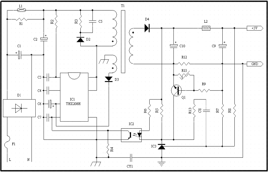
...but with a few simplifications (the low cost device is made even cheaper?). One is that the Y suppressor capacitor is omitted, great for safety but not so great for EMI suppression. Another is an inductor at primary side (simple line filter?). Bad EMI to expect from this then? Maybe, I don't have any tools or knowledge about EMC, but we'll see if there're any signs of this later perhaps... The HLK-PM01 EMC review is my reference of about what to expect.
Visual check
It looks OK, without any apparent insane design choices. Creepage distance around mains input is as usual unnecessary small. It's barely the required 3mm so keep it away from polluted environment and have good fuses before it. The primary-secondary distance looks good, with only the transformer and opto-coupler interconnecting.Load test measurements
Test input voltage: 239Vrms
No load output voltage: 11.85V
No load input current(AC): 2.4mA
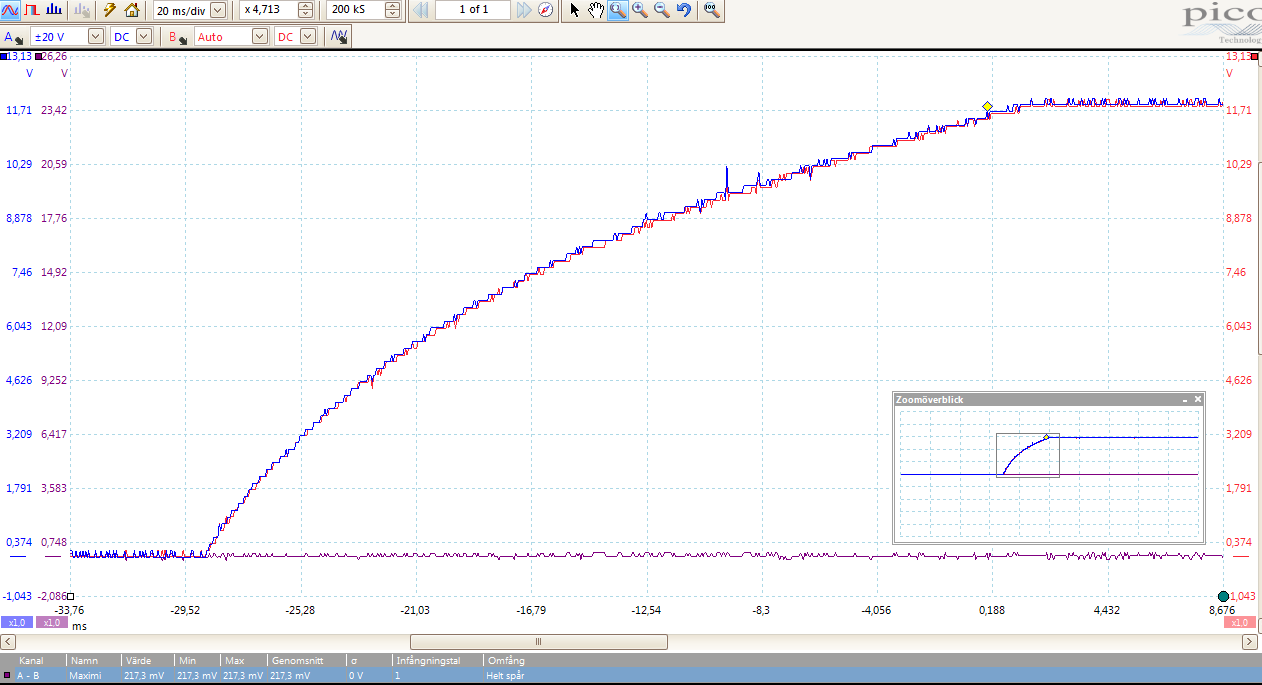
Load test presented below was conducted by applying a 150uF cap together with a few different resistive values. Different cap values (0-2mF) had a small impact on latest half of the output voltage rising slope, nothing else. 150uF was left through the rest of the tests to simulate a realistic value.
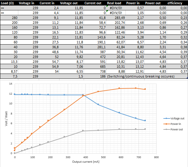
Maximum overload: n/a
As the current/load increases above nominal current 400mA, the controller effectively decreases voltage to keep within constant max power 4.8W. At 185% nominal current, it starts cutting off the output repeatedly at 2-3Hz.Output voltage ripple
At no load: 52mVrms
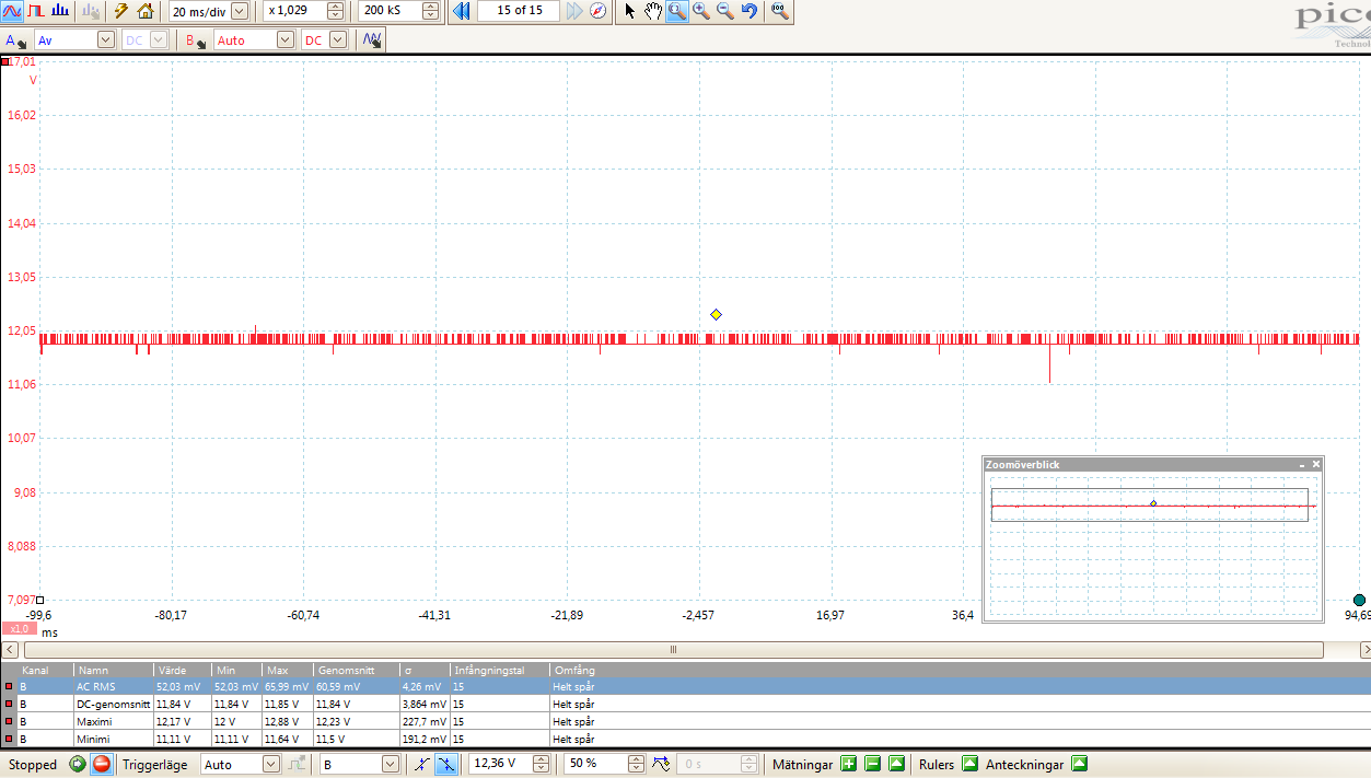
At nominal load: 76mVrms
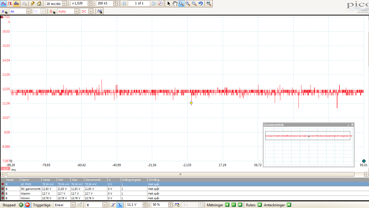
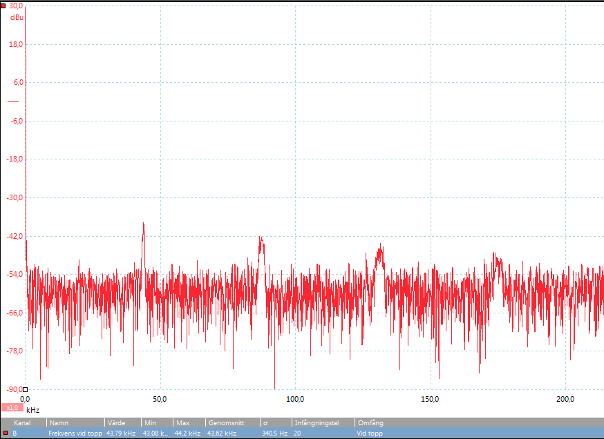
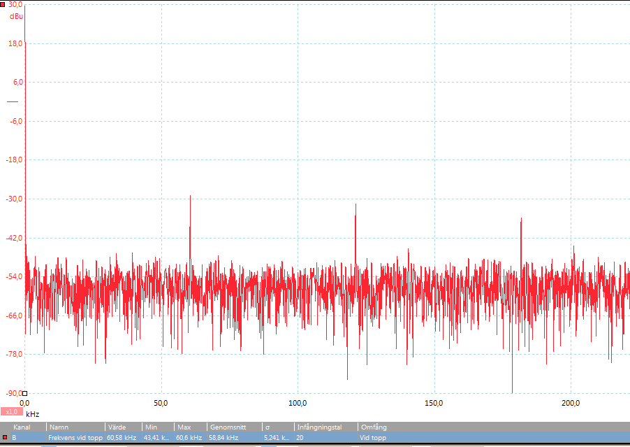
Switch frequency: 40-60kHz (increasing with load)
Half load:
Full (nominal) load:
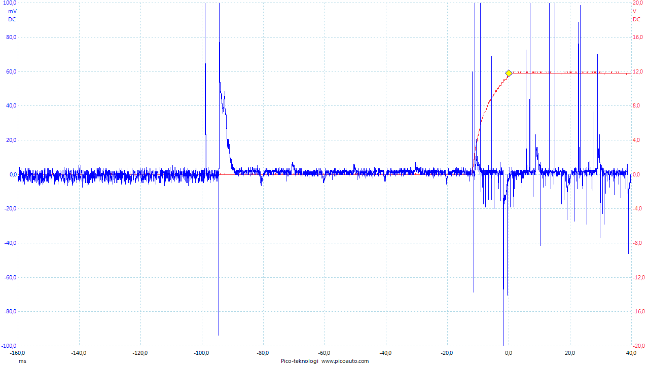
Startup time tests showed variations depending on line phase, load/load-type and unknown factors. Numbers presented below are averages from a lot of sample startup tests and typical characteristics are shown. A current probe (100mV/A) is used on AC input wire.
Controller startup time (from power-on until the beginning of output voltage increase): 15-20ms
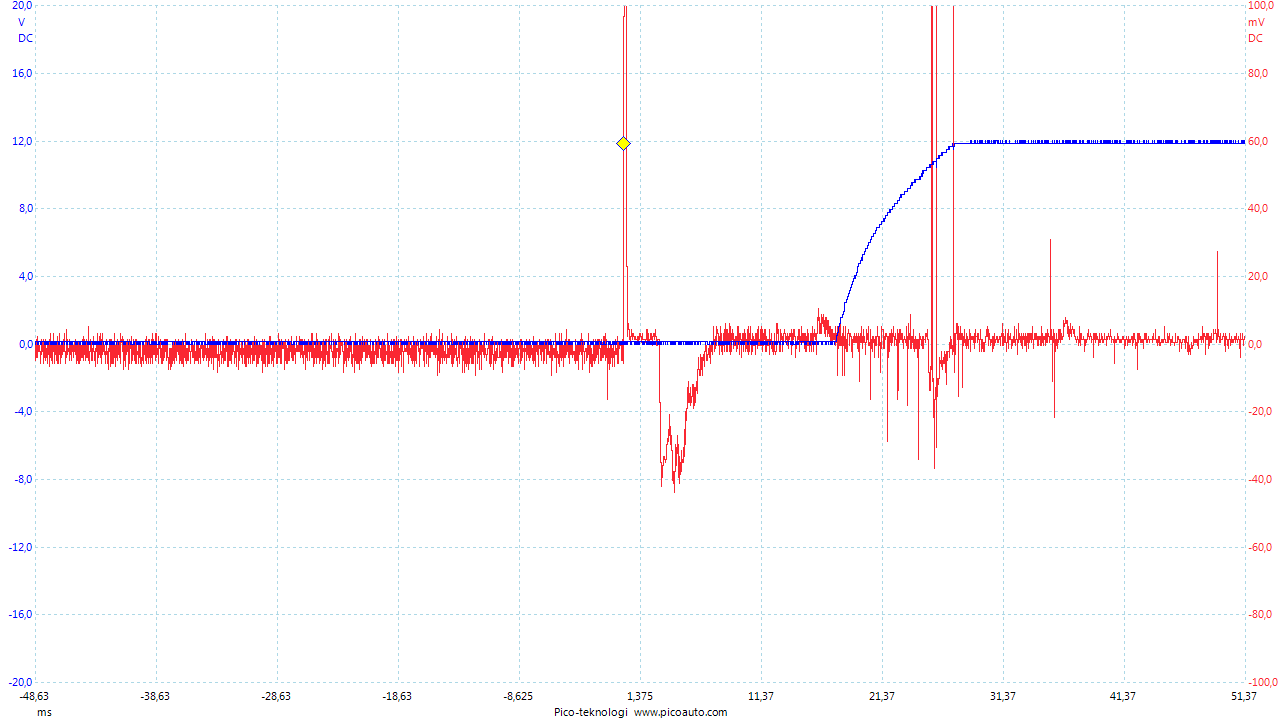
There also a strange phenomenon where startup time sometimes is ~100ms. I haven't been able to figure out when or why it happens, but there seems to be some correlation with high loads, load time and frequent startups.
Voltage rise time, no load: 7ms
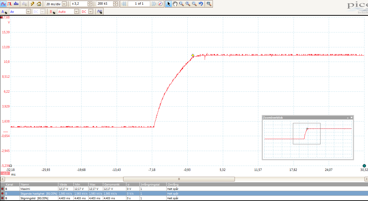
Voltage rise time, full load: 15-20ms
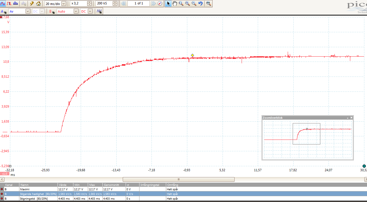
Voltage rise time, 1.5mF load: 30ms
A quick reconnect results in a little faster uptime but no notable difference in inrush current. The on-board output ballast (LED) de-energizes the load capacitor pretty fast.
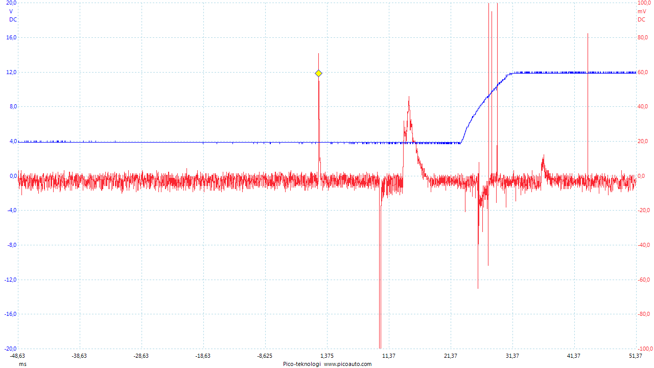
Inrush current and fuse value
Since using a fuse at the input to this supply is a very good safety practice, we need to know the expected current characteristics. Especially during startup when there's high currents even for moderate loads (link) . I had some theories and calculations posted in the "Safe in wall..."-thread . From the measurements presented in this post it looks that I was rather correct in my assumption regarding the first inrush current, but rather wrong about the succeeding one.
The first 1-2 peaks when energizing the filter cap has very high current, but very short duration (<1ms) which won't melt a normal fast fuse. Sometimes this first quick inrush impulses are several due to bouncing connectors and when in the line phase it connects.

The second one though was not as I thought. It was not related to load or output voltage raise. It was actually very unpredictable and could even superimpose on the first filter inrush current. In total worst case then there is a <1ms peak at >10xIn followed by 3-4ms at ~0.4A. If I've read IEC 60127 -1 and -2 correct, the fuse must have pre-arcing at 2xIn, meaning 0.2A fuse is on the edge and 0.3, 0.4 or even 0.5A would probably be better. I think 0.5A is the most common and easiest to find. The disadvantage with a too low value is wear and frequent spurious fuse blows with the risk of user neglecting real issues instead.
Since there's completely silent on the secondary (output) side, my guess is that this "second inrush" power is dissipated by the controller for some reason. - If an expert or anybody knows more about this or have another guess your welcome.Operating temperatures
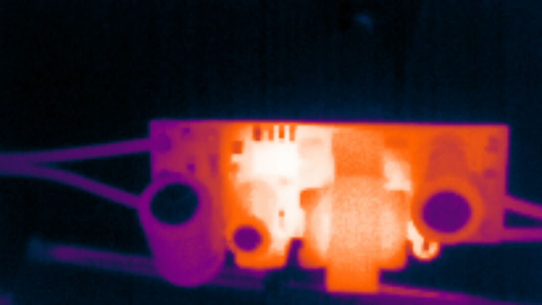
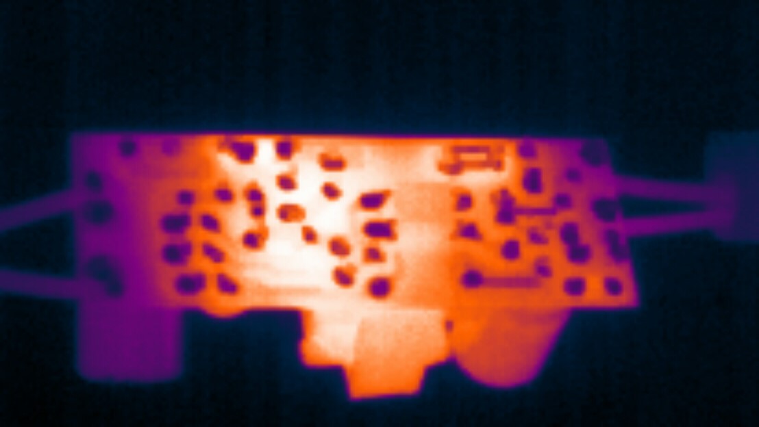
Max temperature at nominal load: 65'C
A maximum and stable temperature was reached after ~5min and remained the same until the test stopped after 60 min. The controller IC and the rectifying diode heats up pretty fast and to the same temperature. A litte faster and 1-2'C more for the controller. As the time goes the transformer will heat up as well. Probably partly because those hot components on each side.
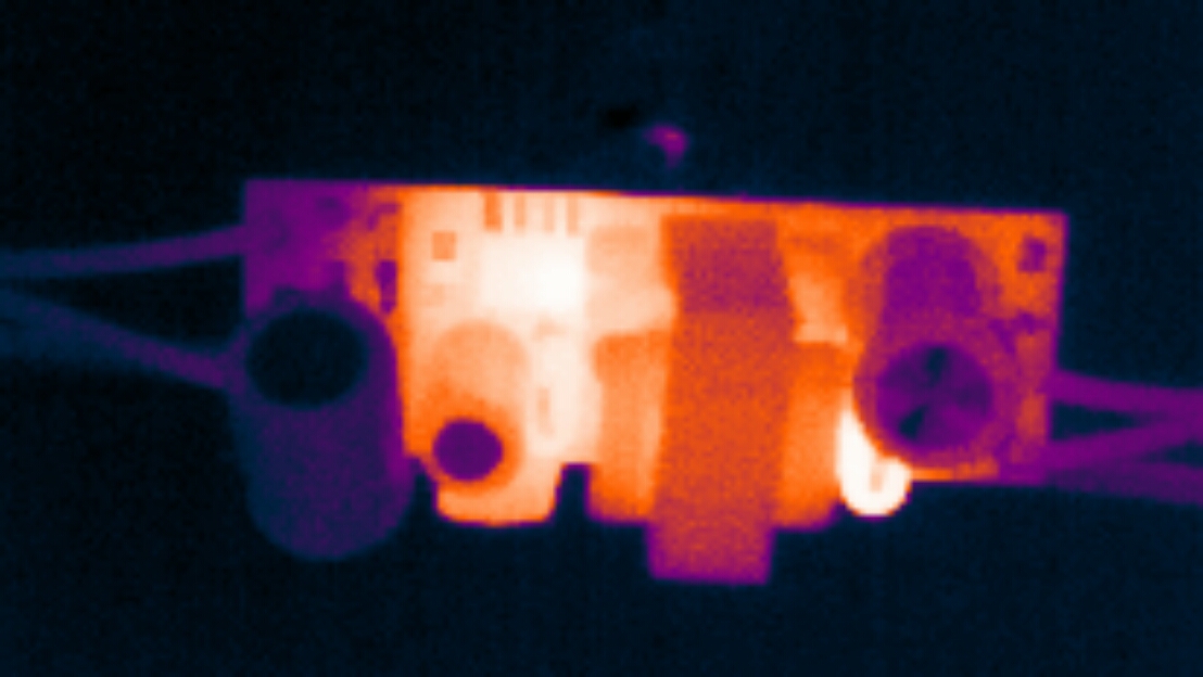
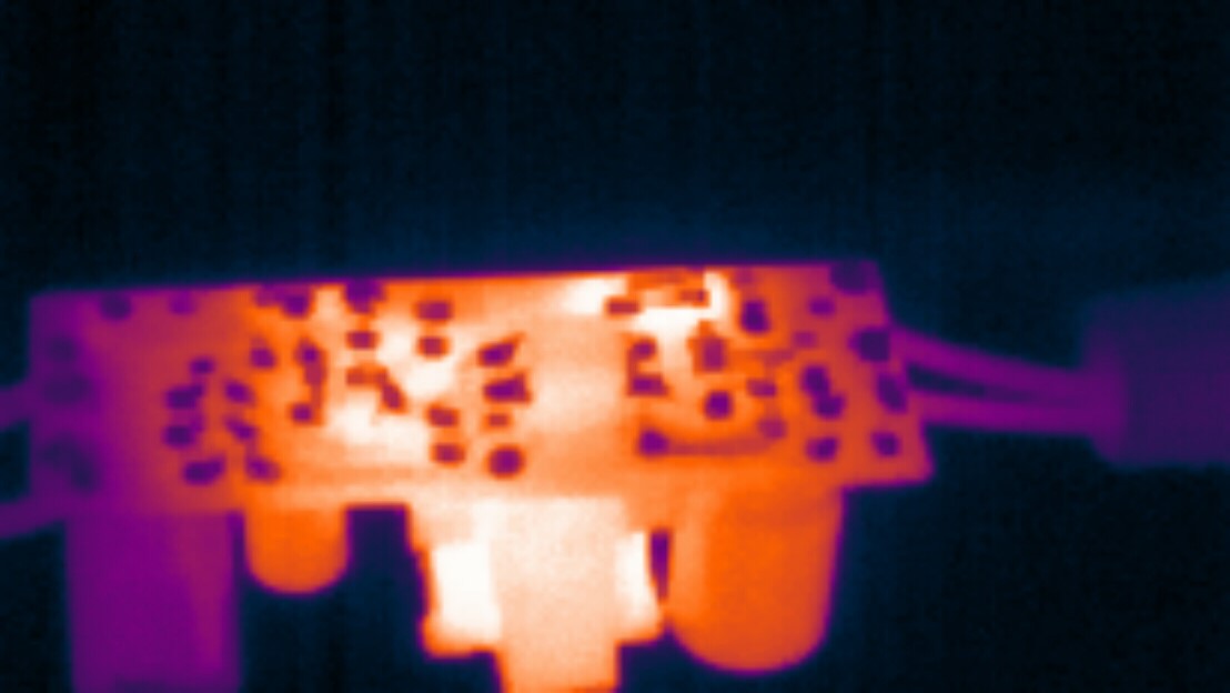
Max temperature at "overload": 75'C
Because of the controller overload protection, the supply can't be overloaded in the true meaning. Here's the study of high-current-low-voltage condition right before it enters protection mode with repeatedly switching on and off, and everything cool down. Just like the nominal case, the temperature stabilizes fast and stays there. The most notable difference in this case is the rectifier diode gets hotter than the controller (~5'C).
Noise
EMI is another great concern regarding these kinds of cheap Chinese power supplies. The HLK-PM01 EMC test confirms this and don't expect the YS-12V400-B to be any better. I don't have the equipment or knowledge to test EMC/EMI, but I have my Picoscope and two AC current probes I can use to study the device at different loads and so on. I assume this can be used to give an idea of what to expect.
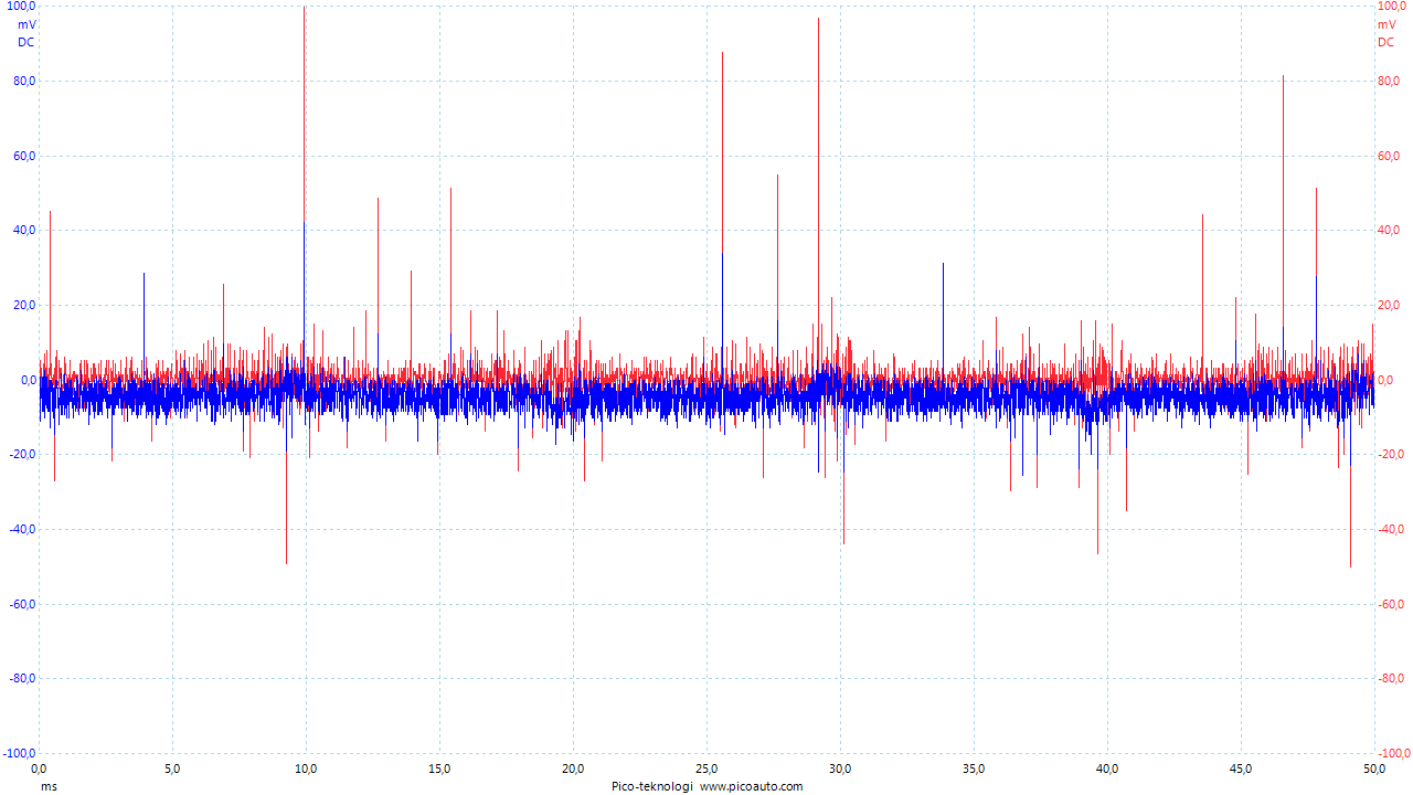
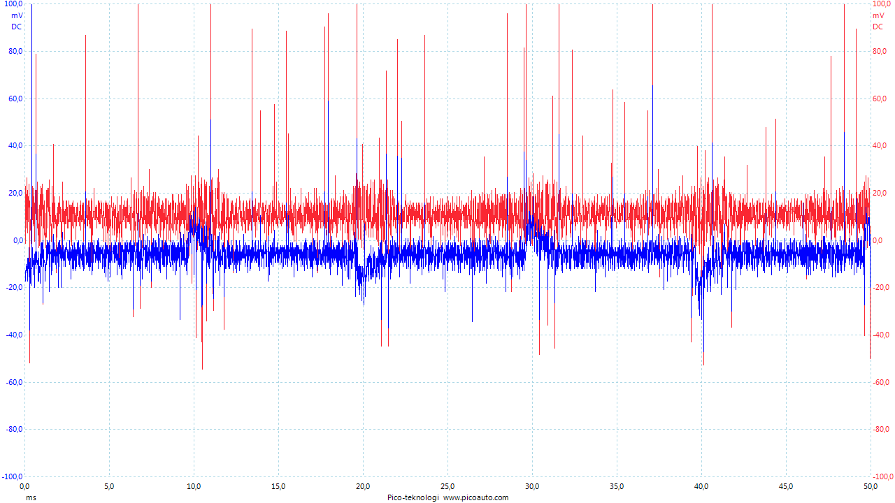
First its easy to see from the startup measurements above that there's more noise during the rise of output voltage. There's also a correlation between increased load and increased current noise.
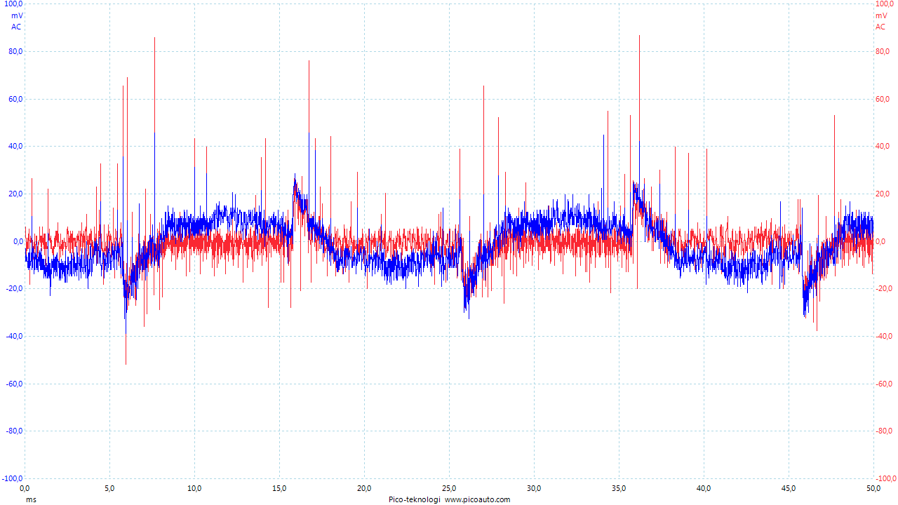
Here's a comparison between low load (280ohm) and nominal load (30ohm) in time domain (Blue=I_in, Red=I_out):
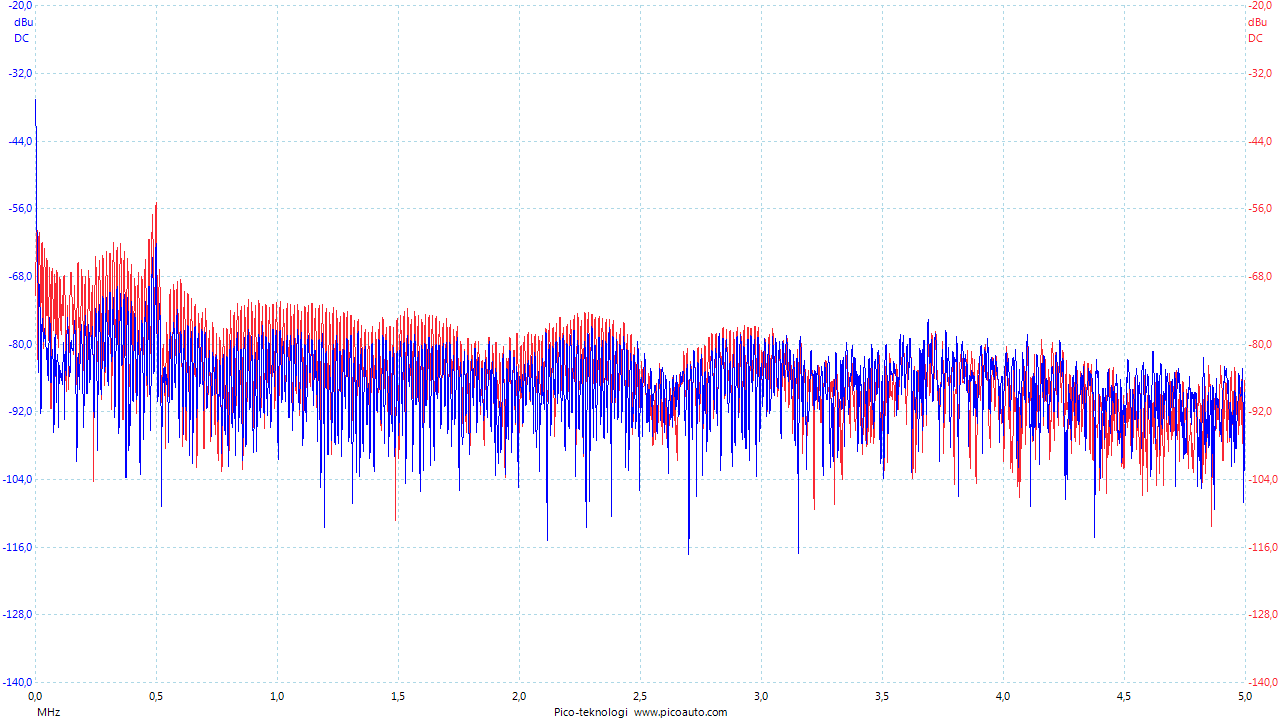
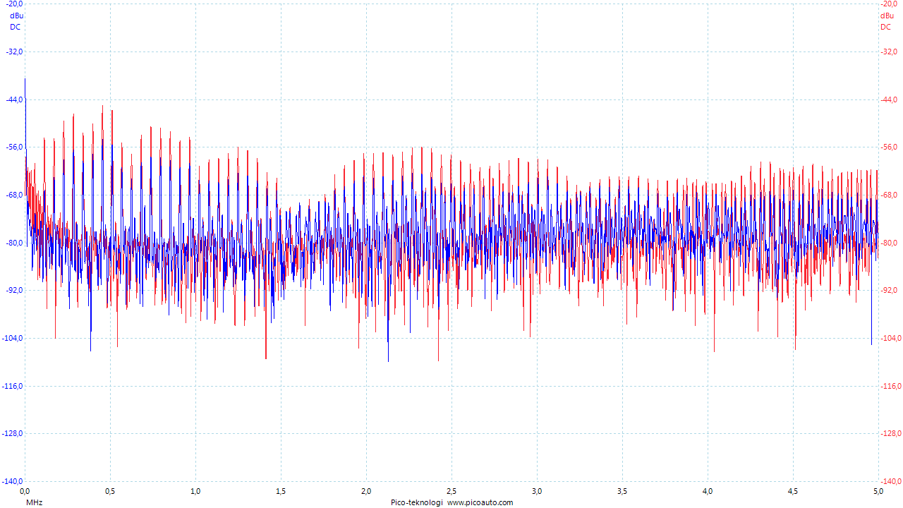
and in the frequency domain:
As an experiment I applied the line filter from a good quality 300W old computer PSU. It's actually a two stage filter where one is the common type built into the power cord socket.
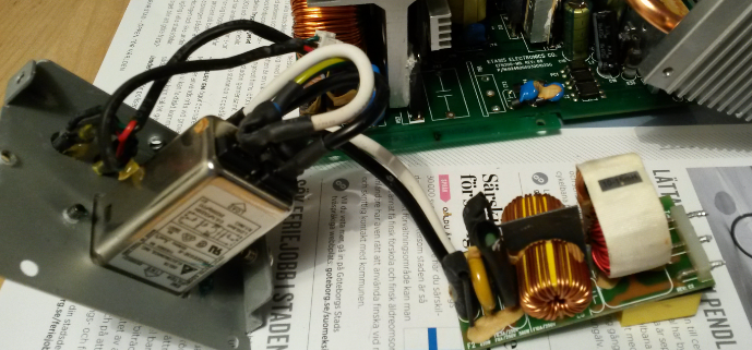
Here's it in action for nominal load (30ohm) (Blue=I_poweroutlet2filter, Red=I_filter2SMPS):
Here's a comparison between nominal load (30ohm) and low load (280ohm):
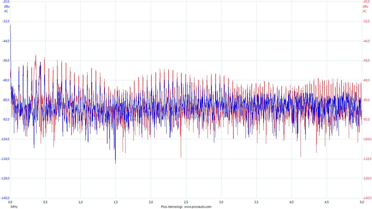
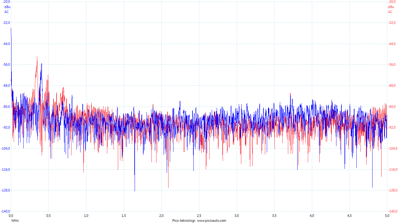
So the conclusion here is that the filter is working, but it's not nearly as effective as using a low load.
If you intend to use any of these supplies at 400mA or perhaps even at 50% continuously, it'd probably be recommended to use one of the models with EMI filter.Conclusion
A few aspects of the supply module have been studied, no issues have been found and it corresponds to the found documentation. EMI is probably OK if the load is small.Design Example
Here is a recent design example with this module:
https://www.openhardware.io/view/47/My-MySensorized-Wall-plug -
Great review!
What is the CY1 capacitor? Looks strange since its the only thing connection primary and secondary ?
Great that it otherwize have the transformer and optocoupler to do that... is this common? Im still learning alot here... -
Great review!
What is the CY1 capacitor? Looks strange since its the only thing connection primary and secondary ?
Great that it otherwize have the transformer and optocoupler to do that... is this common? Im still learning alot here...@sundberg84 It's the omitted Y suppressor cap. Follow the link in the text to read more.
-
Summary
This post shares my own non-professional evaluation of the 230Vac to 12Vdc cheap Chinese converter module (aka Switched Mode Power Supply, SMPS) called YS-12V400-B. It's now rather rare, but instead replaced by the very simmilar HX-12V400X which is found easily on Aliexpress by searching "12V 400mA power supply").
This is not a thorough test. I've looked documentation, load- and temperature- and startup characteristics and did some simple noise filter tests.
I will not give a straight answer to your question "is it safe?", instead I hope to provide information enough for you to draw your own conclusions.
Introduction
I first saw this module from @axillents post in another thread . I bought a batch almost a year ago , but haven't had the time to look at it until now. Now, a quick look at Ali tells me that it has become rather popular at a few sellers, but there's still no reviews to find. Some user comments I found here .There is a new variant of the YS-12V400-B called HX-12V400X where the first (of few?) differences I can see from photos is that a clear blue (XY-grade?) high voltage capacitor has replaced a flat dark green one. Also there's an anti-creepage hole removed near mains input, where a pad has been changed instead. The HX-12V400X seems to be the most common one available on Ali and should probably be better to buy. The one I bought is gone of course. Here's one of few old ones, though.
Like everybody else, I'm looking for a small supply for my projects. The HLK-PM01 is bulky and I don't see a great value of the enclosure when the bare 230V pins are still there. Also, I care about safety and would not feel comfortable with this kind of unknown quality supply in a class III appliance device where secondary side is touchable. I'd prefer a metal case (class I) for safety earthing and fire protection, but it's not always very economical or practical so I then put my trust in good fuses, insulation (class II) and protective functions.
Some reasons for me to favour 12V in front of 3.3V and 5V are:
- A strive to standardize parts, reuse and keep my assortment of parts as lean as possible.
- Easily converted to 5V or 3.3V with linear regulator where the extra converter's power supply ripple rejection (PSRR) is desired.
- I don't mind the small extra loss or heat due to 5V or 3.3V conversion.
- Flexible in respect of component selection and circuit design. Particularly when dealing with electromechanics like relays and servos.
- Preferable if one wish to distribute power further without to much loss and voltage drop.
- Less current and smaller components.
- Works with Arduino Pro Mini internal regulator. (Note that some APM clones can't handle 12V.)
Since the HLK-PM01 has become our reference device after the famous lygte-info.dk review , I've been thinking that some kind of testing and closer look needs to be done before using ANY kind of Chinese SMPS. I may not have all equipment or skill, but with a small effort a lot can be done. At least to reassure myself that the device is useable (or not). Still, I don't consider anything but certified products as "safe".
Documentation
Official specifications are hard to find and very limited as usual when it comes to these cheap Chinese products:
Dimensions: :4 x1.5 x 1.8cm
Input voltage:AC 90V~240V 50/60HZ
Output voltage:DC 12V (±0.2V)
Output Current: 400mA
Output power: 4.8W
90V~240V AC Input,Constant 12V DC Output ,Ultra small,Precision
Application: the power adapter,industrial equipment,microcontroller,LED lighting power supply, etc
AC input:Does not distinguish between live line and null line.
Protection functions:YES
Shortage Protection:YES
Temperature protection:YES
Overcurrent protection:YESA look through the magnifier reveals the controller IC name "THX208", which then provided a pretty good datasheet . (Of course you might need a translation tool, but after that it's very readable). It turns out that the power supply module we're studying is designed very close the provided typical circuit:
...but with a few simplifications (the low cost device is made even cheaper?). One is that the Y suppressor capacitor is omitted, great for safety but not so great for EMI suppression. Another is an inductor at primary side (simple line filter?). Bad EMI to expect from this then? Maybe, I don't have any tools or knowledge about EMC, but we'll see if there're any signs of this later perhaps... The HLK-PM01 EMC review is my reference of about what to expect.
Visual check
It looks OK, without any apparent insane design choices. Creepage distance around mains input is as usual unnecessary small. It's barely the required 3mm so keep it away from polluted environment and have good fuses before it. The primary-secondary distance looks good, with only the transformer and opto-coupler interconnecting.Load test measurements
Test input voltage: 239Vrms
No load output voltage: 11.85V
No load input current(AC): 2.4mA
Load test presented below was conducted by applying a 150uF cap together with a few different resistive values. Different cap values (0-2mF) had a small impact on latest half of the output voltage rising slope, nothing else. 150uF was left through the rest of the tests to simulate a realistic value.
Maximum overload: n/a
As the current/load increases above nominal current 400mA, the controller effectively decreases voltage to keep within constant max power 4.8W. At 185% nominal current, it starts cutting off the output repeatedly at 2-3Hz.Output voltage ripple
At no load: 52mVrms
At nominal load: 76mVrms
Switch frequency: 40-60kHz (increasing with load)
Half load:
Full (nominal) load:
Startup time tests showed variations depending on line phase, load/load-type and unknown factors. Numbers presented below are averages from a lot of sample startup tests and typical characteristics are shown. A current probe (100mV/A) is used on AC input wire.
Controller startup time (from power-on until the beginning of output voltage increase): 15-20ms
There also a strange phenomenon where startup time sometimes is ~100ms. I haven't been able to figure out when or why it happens, but there seems to be some correlation with high loads, load time and frequent startups.
Voltage rise time, no load: 7ms
Voltage rise time, full load: 15-20ms
Voltage rise time, 1.5mF load: 30ms
A quick reconnect results in a little faster uptime but no notable difference in inrush current. The on-board output ballast (LED) de-energizes the load capacitor pretty fast.
Inrush current and fuse value
Since using a fuse at the input to this supply is a very good safety practice, we need to know the expected current characteristics. Especially during startup when there's high currents even for moderate loads (link) . I had some theories and calculations posted in the "Safe in wall..."-thread . From the measurements presented in this post it looks that I was rather correct in my assumption regarding the first inrush current, but rather wrong about the succeeding one.
The first 1-2 peaks when energizing the filter cap has very high current, but very short duration (<1ms) which won't melt a normal fast fuse. Sometimes this first quick inrush impulses are several due to bouncing connectors and when in the line phase it connects.
The second one though was not as I thought. It was not related to load or output voltage raise. It was actually very unpredictable and could even superimpose on the first filter inrush current. In total worst case then there is a <1ms peak at >10xIn followed by 3-4ms at ~0.4A. If I've read IEC 60127 -1 and -2 correct, the fuse must have pre-arcing at 2xIn, meaning 0.2A fuse is on the edge and 0.3, 0.4 or even 0.5A would probably be better. I think 0.5A is the most common and easiest to find. The disadvantage with a too low value is wear and frequent spurious fuse blows with the risk of user neglecting real issues instead.
Since there's completely silent on the secondary (output) side, my guess is that this "second inrush" power is dissipated by the controller for some reason. - If an expert or anybody knows more about this or have another guess your welcome.Operating temperatures
Max temperature at nominal load: 65'C
A maximum and stable temperature was reached after ~5min and remained the same until the test stopped after 60 min. The controller IC and the rectifying diode heats up pretty fast and to the same temperature. A litte faster and 1-2'C more for the controller. As the time goes the transformer will heat up as well. Probably partly because those hot components on each side.
Max temperature at "overload": 75'C
Because of the controller overload protection, the supply can't be overloaded in the true meaning. Here's the study of high-current-low-voltage condition right before it enters protection mode with repeatedly switching on and off, and everything cool down. Just like the nominal case, the temperature stabilizes fast and stays there. The most notable difference in this case is the rectifier diode gets hotter than the controller (~5'C).
Noise
EMI is another great concern regarding these kinds of cheap Chinese power supplies. The HLK-PM01 EMC test confirms this and don't expect the YS-12V400-B to be any better. I don't have the equipment or knowledge to test EMC/EMI, but I have my Picoscope and two AC current probes I can use to study the device at different loads and so on. I assume this can be used to give an idea of what to expect.
First its easy to see from the startup measurements above that there's more noise during the rise of output voltage. There's also a correlation between increased load and increased current noise.
Here's a comparison between low load (280ohm) and nominal load (30ohm) in time domain (Blue=I_in, Red=I_out):
and in the frequency domain:
As an experiment I applied the line filter from a good quality 300W old computer PSU. It's actually a two stage filter where one is the common type built into the power cord socket.
Here's it in action for nominal load (30ohm) (Blue=I_poweroutlet2filter, Red=I_filter2SMPS):
Here's a comparison between nominal load (30ohm) and low load (280ohm):
So the conclusion here is that the filter is working, but it's not nearly as effective as using a low load.
If you intend to use any of these supplies at 400mA or perhaps even at 50% continuously, it'd probably be recommended to use one of the models with EMI filter.Conclusion
A few aspects of the supply module have been studied, no issues have been found and it corresponds to the found documentation. EMI is probably OK if the load is small.Design Example
Here is a recent design example with this module:
https://www.openhardware.io/view/47/My-MySensorized-Wall-plug@m26872
A review like this is worth a prize in it's own right ! Excellent work, thank you ! -
@m26872: impressive work :) I have some of these too but still in a box...
I still use for the moment hilink, for the package and easier integration on my pcb (and it is almost the same size). but I agree with you for the 12v vs 5v and about insulation. I will look what you plan to do with these ;) thx for share. -
@m26872 Great - thank you!
And again, its a excellent review and worth alot for future considerations in power. -
Nice work. :+1:
But I'm sure, it's too risky to use this power supply instead of HLK-PM01 (or other more or less "correct module").
Power supply without creepage barrier is scary. It's industrial standard, even for the cheapest solutions.
But omitted suppresion XY capacitor - disaster. It could be the cause of many indeterminate bugs, becouse your device will be helpless before common-mode interference. Also I can recommend using X capacitor (X has less protection requirements than Y) in input of power supply if it doesn't contain it.
To put it another way, it's not only the problem with EMI compatibility, it's the problem for your device stability.
Hello! It looks like you're interested in this conversation, but you don't have an account yet.
Getting fed up of having to scroll through the same posts each visit? When you register for an account, you'll always come back to exactly where you were before, and choose to be notified of new replies (either via email, or push notification). You'll also be able to save bookmarks and upvote posts to show your appreciation to other community members.
With your input, this post could be even better 💗
Register Login