CE line on sensor node?
-
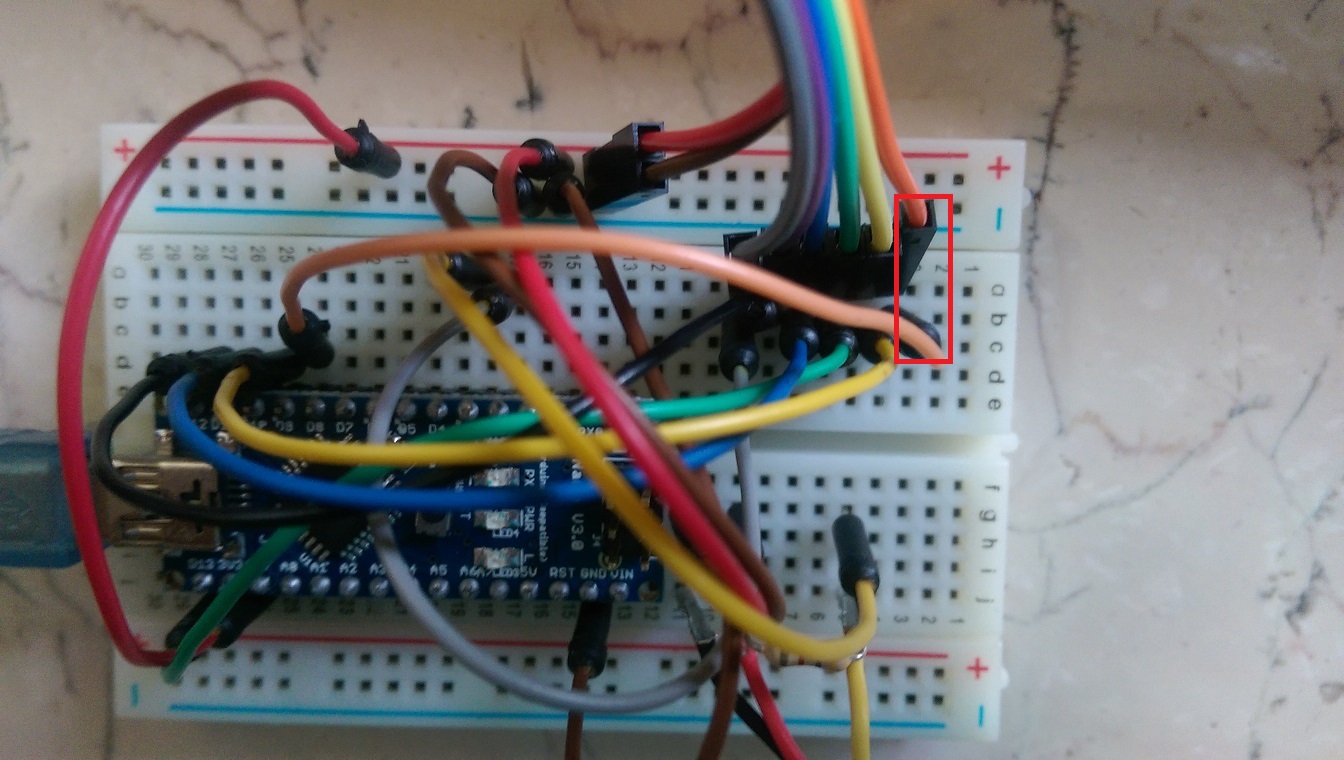
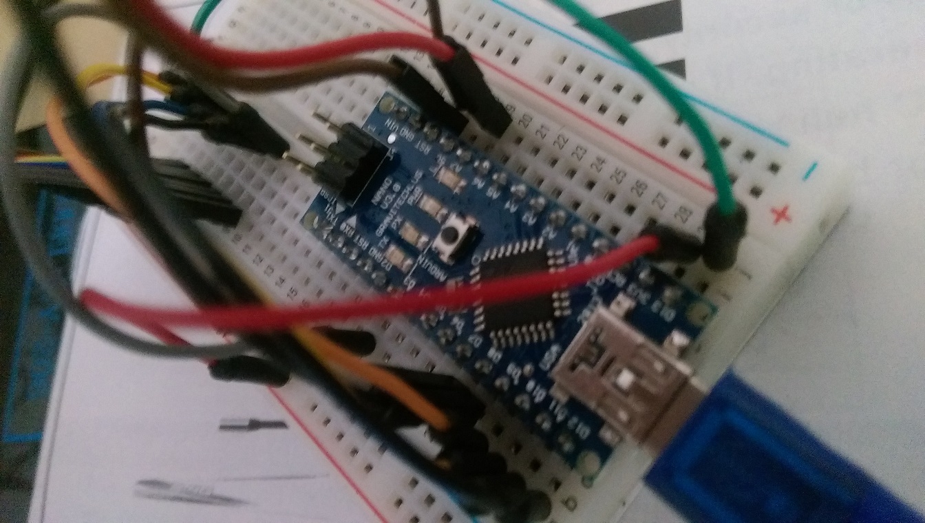
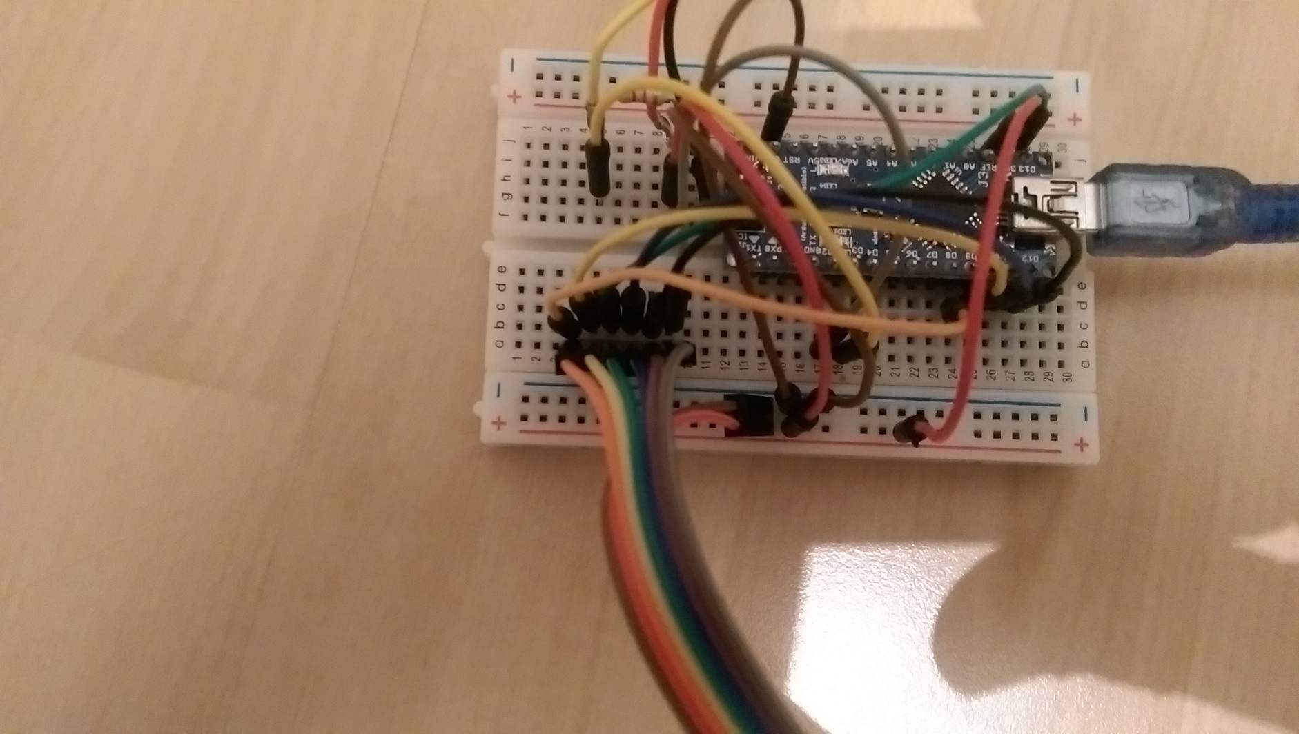
If I disconnect orange wire (red marker on first sensor picture), sensor works fine.
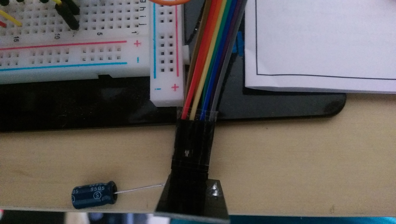
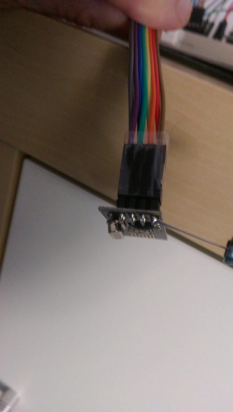
Sensor figures:
Gateway figures:
-
@aquapro sagte:> Hi,
I have tested 1000 times, wasted complete weekend. Rechecked with built up the wiring from scratch. Same Problem.
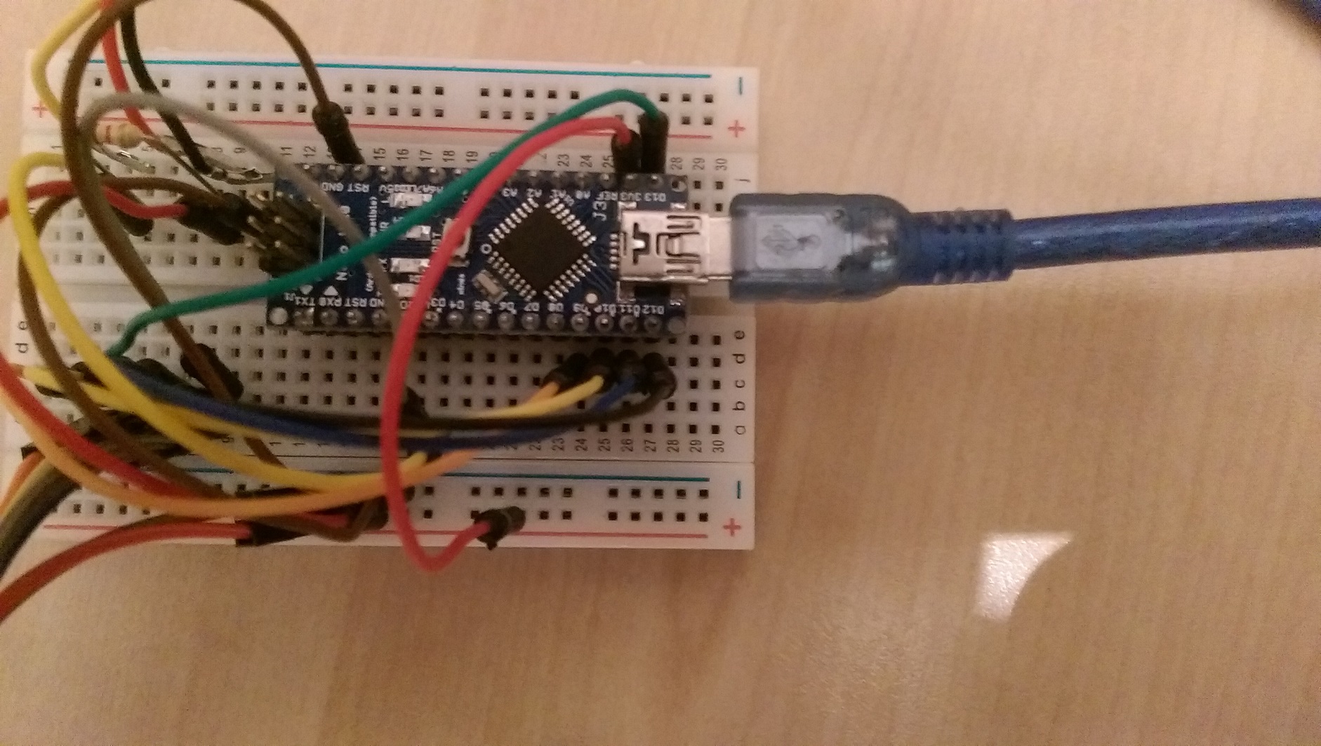
Suppose I have swap the cables, which I doubt, why it works when I disconnect it completely?I have all the cables replaced, also new from different suppliers. I used the next pins on the Arduino. For the pictures I have to build something stretched to better overview.
-
@aquapro sagte:> Hi,
I have tested 1000 times, wasted complete weekend. Rechecked with built up the wiring from scratch. Same Problem.
Suppose I have swap the cables, which I doubt, why it works when I disconnect it completely?I have all the cables replaced, also new from different suppliers. I used the next pins on the Arduino. For the pictures I have to build something stretched to better overview.
-
If I disconnect orange wire (red marker on first sensor picture), sensor works fine.
Sensor figures:
Gateway figures:
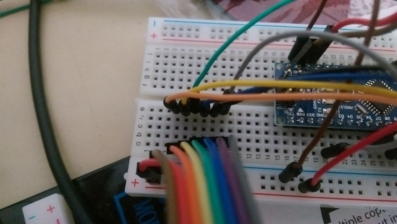
@aquapro The MySensors site (http://www.mysensors.org/build/connect_radio) gives the following wiring:
Arduino     nRF24
9           CE
10          CSN
13          SCK
11          MOSI
12          MISO
2           IRQ
These are the defaults for the library. CE & CSN you can adapt through the constructor of MySensor (did you do that?)
Looking at the pictures I have a hard time figuring out the connections for pins 8..12, while these are just the interesting part...
-
hello,
very good project!
I currently testing version 1.4b1 and I have a problem. Only if I disconnect the CE line on the sensor, the values are transferred.
If the CE line is connected, only one part will be sent, see Figure 1, the LED on the sensor remains on. As soon as I disconnect CE line, all values are not sent are transmitted (Figure 2) and the LED goes out and lights up briefly in the next transmission.Does anyone have an idea?
greeting
aqua
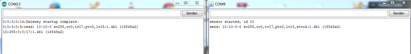
Figure1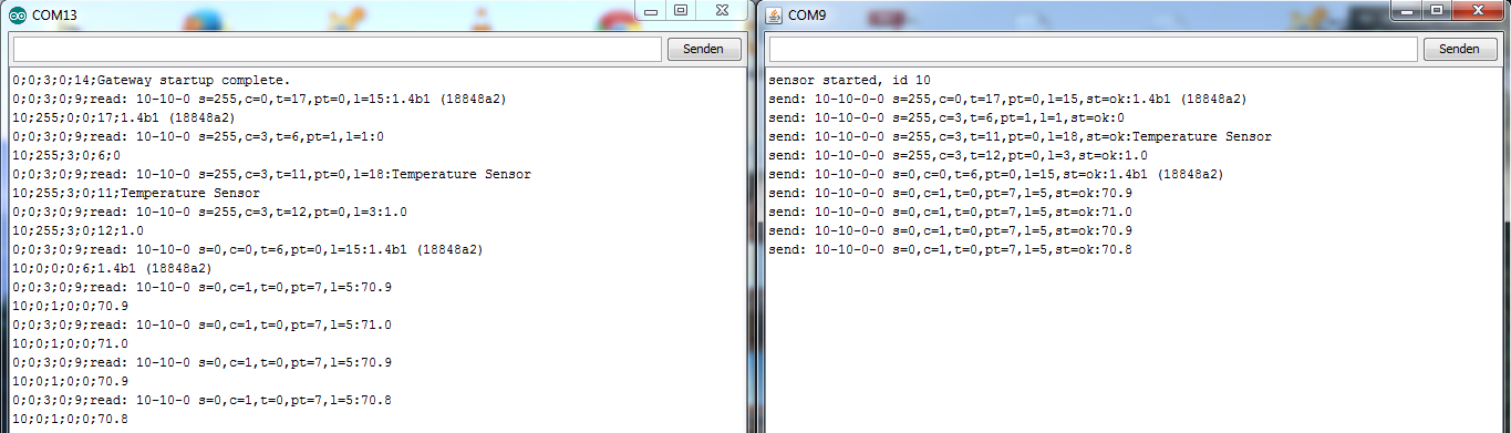
Figure 2@aquapro Hmmmm
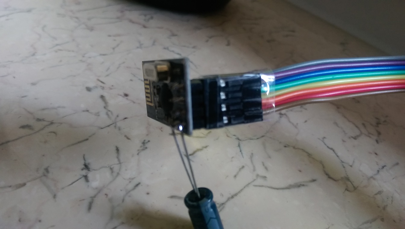
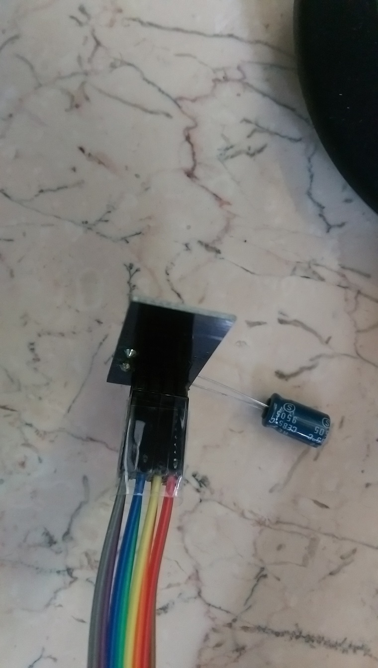
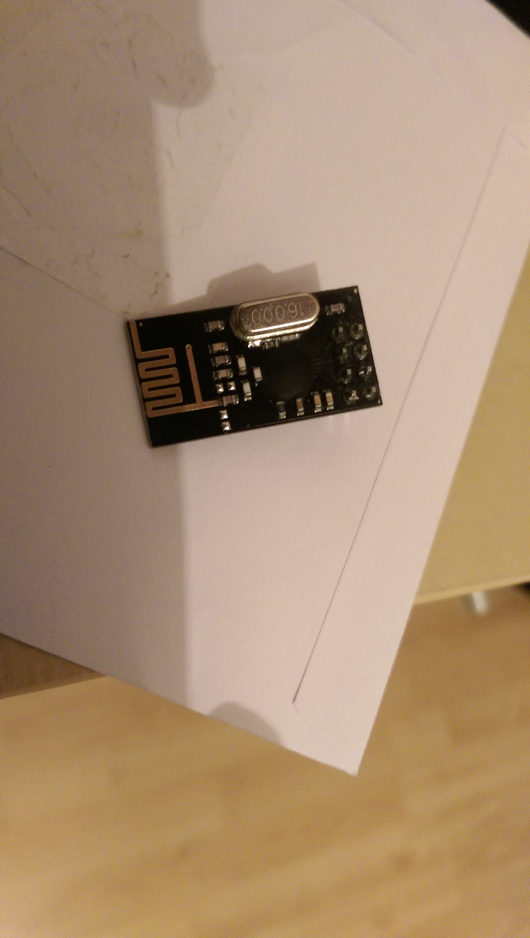
The chip on your looks like a blob more than this; You might have gotten a chinese ripoff .. I dont remember the chip name... Hmmmm hard to see!edit:
maybe : http://forum.mysensors.org/topic/300/rfm73-experience/ ?
inverted CE?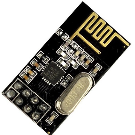
-
@aquapro Hmmmm
The chip on your looks like a blob more than this; You might have gotten a chinese ripoff .. I dont remember the chip name... Hmmmm hard to see!edit:
maybe : http://forum.mysensors.org/topic/300/rfm73-experience/ ?
inverted CE? -
@aquapro Hmmmm
The chip on your looks like a blob more than this; You might have gotten a chinese ripoff .. I dont remember the chip name... Hmmmm hard to see!edit:
maybe : http://forum.mysensors.org/topic/300/rfm73-experience/ ?
inverted CE? -
@aquapro The MySensors site (http://www.mysensors.org/build/connect_radio) gives the following wiring:
Arduino     nRF24
9           CE
10          CSN
13          SCK
11          MOSI
12          MISO
2           IRQ
These are the defaults for the library. CE & CSN you can adapt through the constructor of MySensor (did you do that?)
Looking at the pictures I have a hard time figuring out the connections for pins 8..12, while these are just the interesting part...
-
Looking at the pictures I have a hard time figuring out the connections for pins 8..12, while these are just the interesting part...
Pin 8?
-
Looking at the pictures I have a hard time figuring out the connections for pins 8..12, while these are just the interesting part...
Pin 8?
@aquapro I dont think you got a nordic semiconductor nrf24l01, What I can find they are only in QFN package.
http://www.nordicsemi.com/eng/Products/2.4GHz-RF/nRF24L01So the specs on that chip may be different. Maybe CE is inverted?
-
Hi,
I have bought the new modules (right on pic), which operate without modification. I simply swapped and all is fine.
What do I do with the other. How can I test inverted.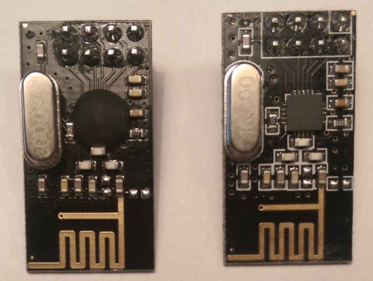
-
If it truly works correctly with CE disconnected, that could be an advantage when there is a shortage of pins (eg: 8 pin ATTiny).
Have you achieved full operation without CE on the old modules?
And did you leave CE floating or tie it high?
Hello! It looks like you're interested in this conversation, but you don't have an account yet.
Getting fed up of having to scroll through the same posts each visit? When you register for an account, you'll always come back to exactly where you were before, and choose to be notified of new replies (either via email, or push notification). You'll also be able to save bookmarks and upvote posts to show your appreciation to other community members.
With your input, this post could be even better 💗
Register Login