Skip to content
  • MySensors
  • OpenHardware.io
  • Categories
  • Recent
  • Tags
  • Popular
Skins
  • Light
  • Brite
  • Cerulean
  • Cosmo
  • Flatly
  • Journal
  • Litera
  • Lumen
  • Lux
  • Materia
  • Minty
  • Morph
  • Pulse
  • Sandstone
  • Simplex
  • Sketchy
  • Spacelab
  • United
  • Yeti
  • Zephyr
  • Dark
  • Cyborg
  • Darkly
  • Quartz
  • Slate
  • Solar
  • Superhero
  • Vapor

  • Default (No Skin)
  • No Skin
Collapse
Brand Logo
  1. Home
  2. Troubleshooting
  3. CE line on sensor node?

CE line on sensor node?

Scheduled Pinned Locked Moved Troubleshooting
29 Posts 6 Posters 8.5k Views 1 Watching
  • Oldest to Newest
  • Newest to Oldest
  • Most Votes
Reply
  • Reply as topic
Log in to reply
This topic has been deleted. Only users with topic management privileges can see it.
  • aquaproA aquapro

    Yes, checked with 5 Arduinos (all different vendor's) and 8 radios. Same Problem. I am totally confused.

    RJ_MakeR Offline
    RJ_MakeR Offline
    RJ_Make
    Hero Member
    wrote on last edited by
    #6

    @aquapro

    Have you tried all new wiring?

    RJ_Make

    1 Reply Last reply
    0
    • hekH Offline
      hekH Offline
      hek
      Admin
      wrote on last edited by
      #7

      If you show a few pictures also (closeups!) it might help.

      1 Reply Last reply
      0
      • aquaproA Offline
        aquaproA Offline
        aquapro
        wrote on last edited by
        #8

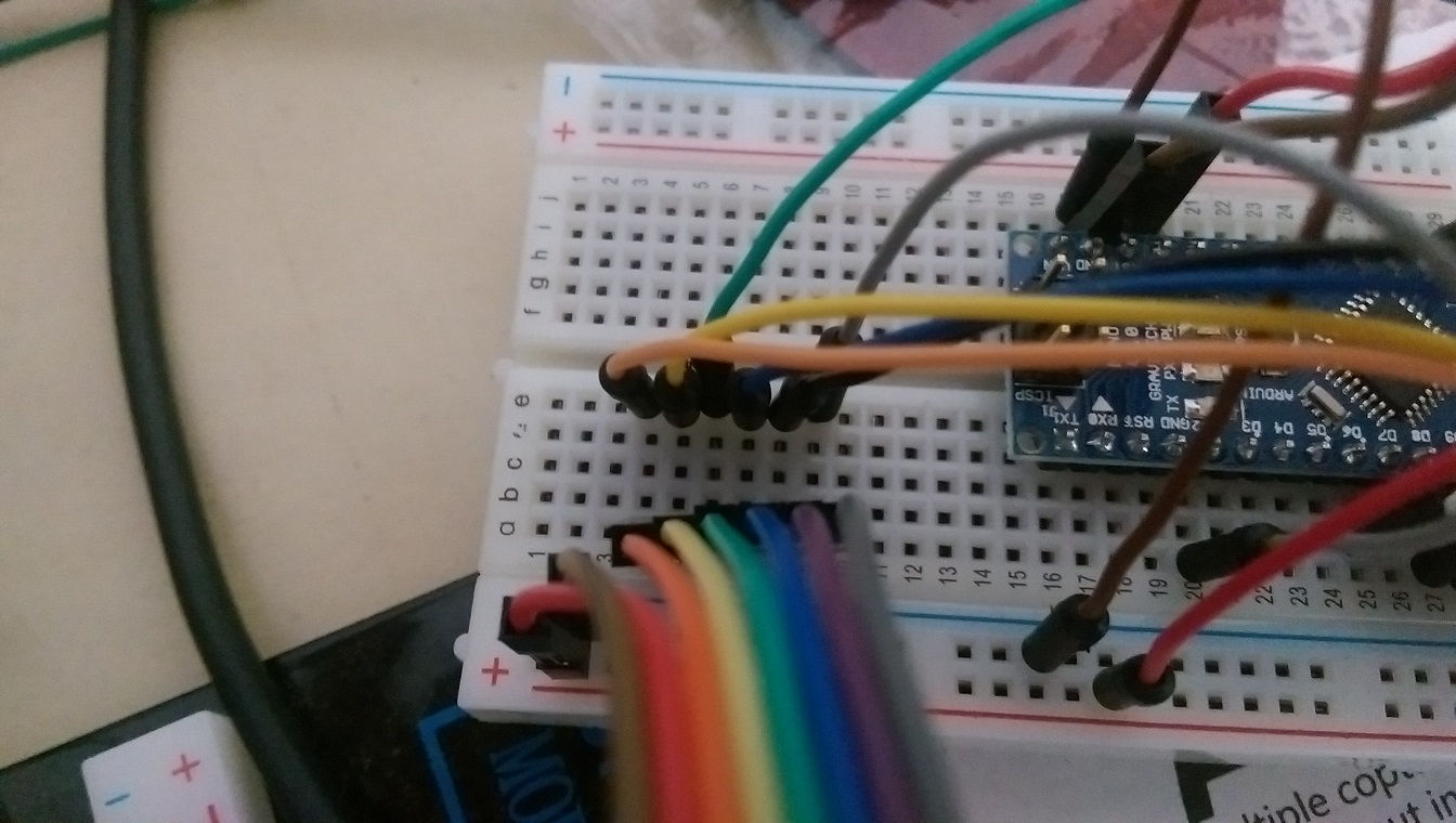
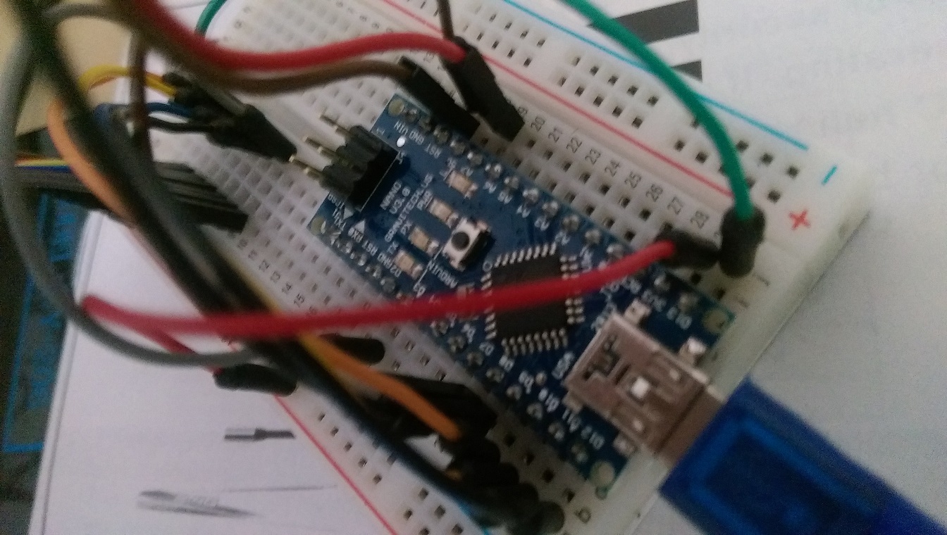
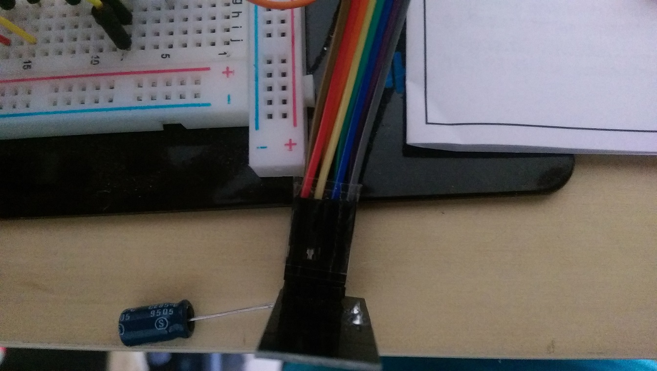
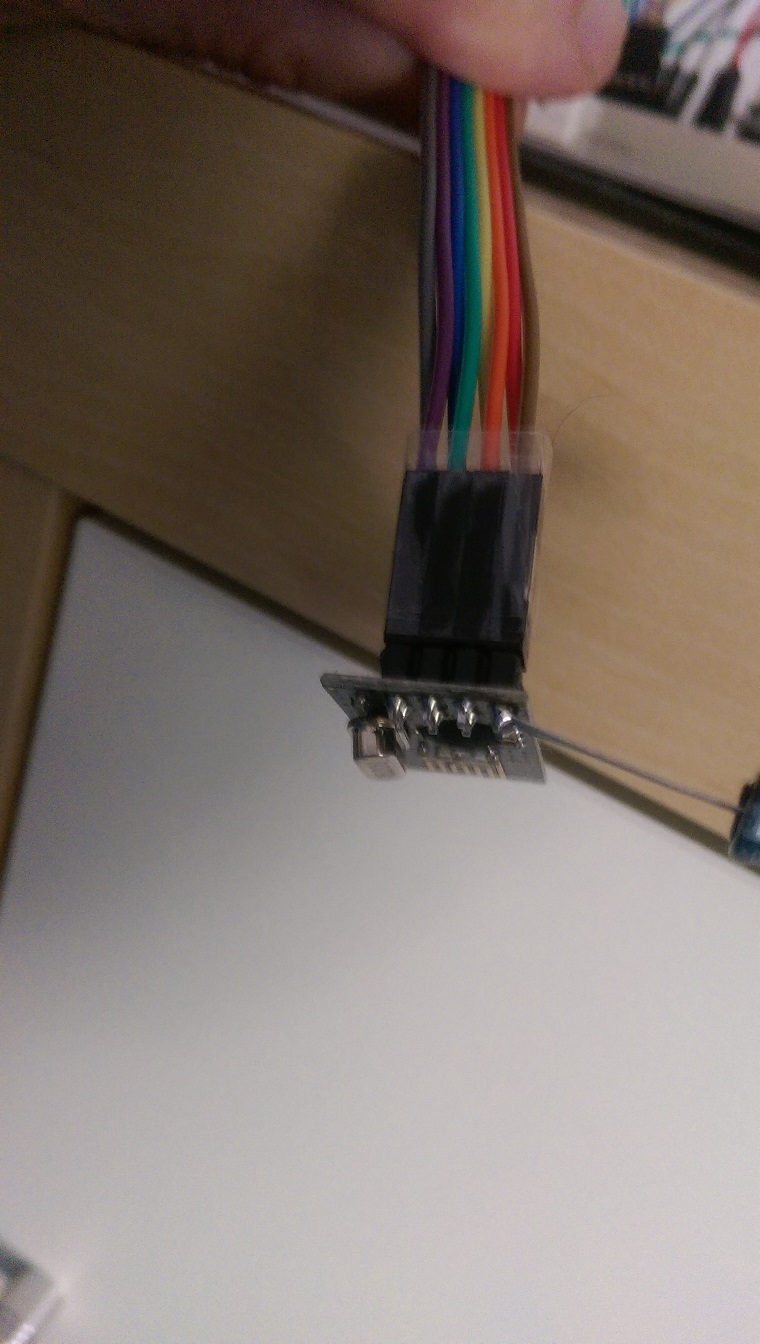
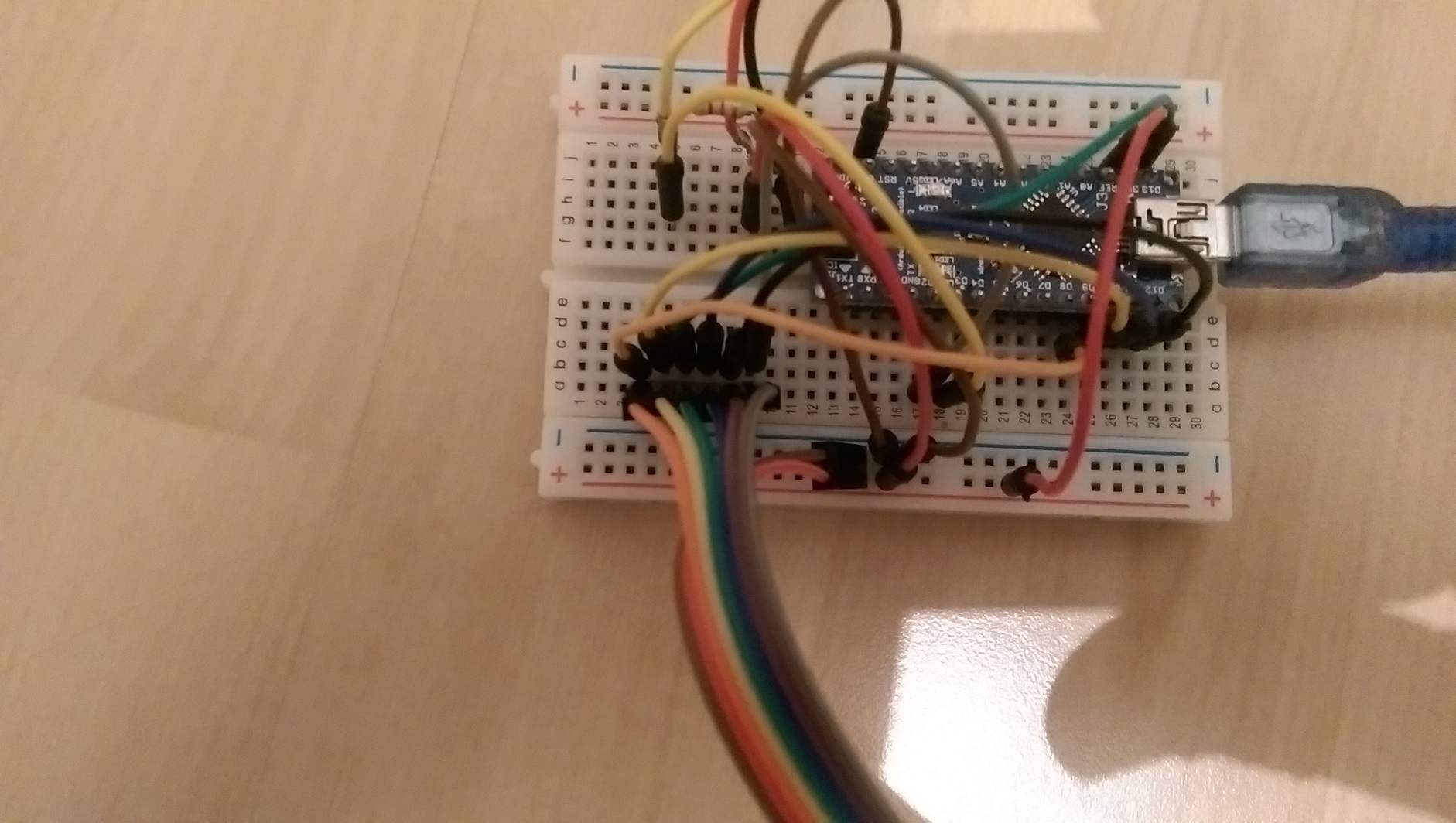
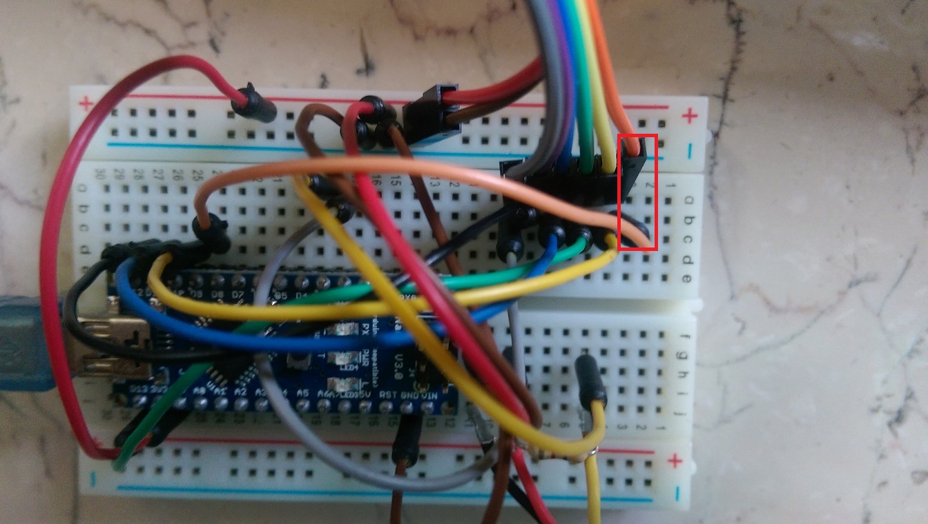
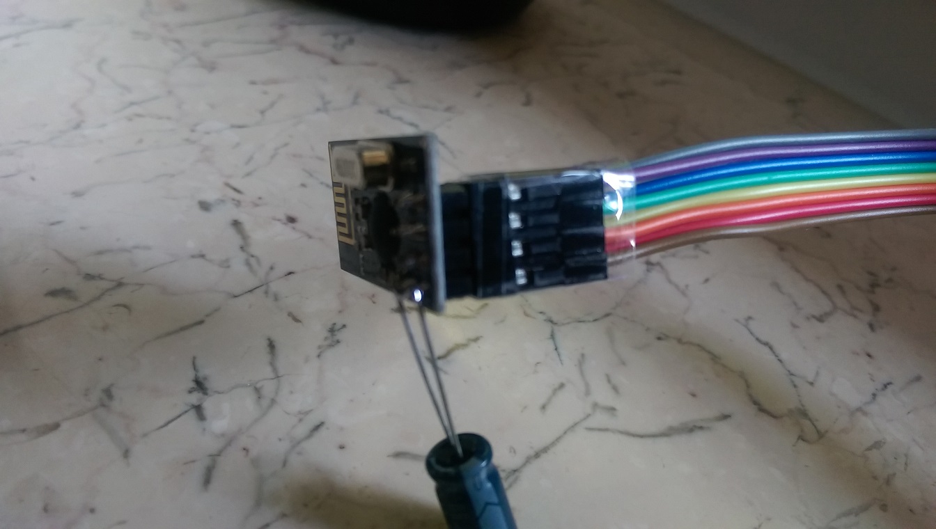
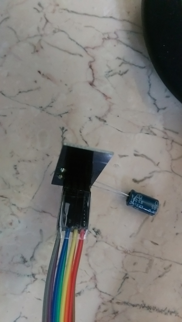
        If I disconnect orange wire (red marker on first sensor picture), sensor works fine.

        Sensor figures:
        IMAG0483a.jpg
        IMAG0484.jpg
        IMAG0485.jpg

        Gateway figures:
        IMAG0486.jpg
        IMAG0487.jpg
        IMAG0488.jpg
        IMAG0490.jpg

        RJ_MakeR YveauxY 2 Replies Last reply
        0
        • aquaproA aquapro

          If I disconnect orange wire (red marker on first sensor picture), sensor works fine.

          Sensor figures:
          IMAG0483a.jpg
          IMAG0484.jpg
          IMAG0485.jpg

          Gateway figures:
          IMAG0486.jpg
          IMAG0487.jpg
          IMAG0488.jpg
          IMAG0490.jpg

          RJ_MakeR Offline
          RJ_MakeR Offline
          RJ_Make
          Hero Member
          wrote on last edited by
          #9

          @aquapro

          I think I would connected the radio directly to the breadboard pins next to the Arduino with new wiring.

          RJ_Make

          1 Reply Last reply
          0
          • aquaproA Offline
            aquaproA Offline
            aquapro
            wrote on last edited by
            #10

            @aquapro sagte:> Hi,

            I have tested 1000 times, wasted complete weekend. Rechecked with built up the wiring from scratch. Same Problem.
            Suppose I have swap the cables, which I doubt, why it works when I disconnect it completely?

            I have all the cables replaced, also new from different suppliers. I used the next pins on the Arduino. For the pictures I have to build something stretched to better overview.

            RJ_MakeR 1 Reply Last reply
            0
            • aquaproA aquapro

              @aquapro sagte:> Hi,

              I have tested 1000 times, wasted complete weekend. Rechecked with built up the wiring from scratch. Same Problem.
              Suppose I have swap the cables, which I doubt, why it works when I disconnect it completely?

              I have all the cables replaced, also new from different suppliers. I used the next pins on the Arduino. For the pictures I have to build something stretched to better overview.

              RJ_MakeR Offline
              RJ_MakeR Offline
              RJ_Make
              Hero Member
              wrote on last edited by
              #11

              @aquapro
              So the pictures don't reflect the current wiring?

              RJ_Make

              1 Reply Last reply
              0
              • aquaproA Offline
                aquaproA Offline
                aquapro
                wrote on last edited by
                #12

                Pictures reflect the curren?t wiring! Same Problem with closer wiring

                1 Reply Last reply
                0
                • aquaproA aquapro

                  If I disconnect orange wire (red marker on first sensor picture), sensor works fine.

                  Sensor figures:
                  IMAG0483a.jpg
                  IMAG0484.jpg
                  IMAG0485.jpg

                  Gateway figures:
                  IMAG0486.jpg
                  IMAG0487.jpg
                  IMAG0488.jpg
                  IMAG0490.jpg

                  YveauxY Offline
                  YveauxY Offline
                  Yveaux
                  Mod
                  wrote on last edited by
                  #13

                  @aquapro The MySensors site (http://www.mysensors.org/build/connect_radio) gives the following wiring:

                  Arduino     nRF24
                  9           CE
                  10          CSN
                  13          SCK
                  11          MOSI
                  12          MISO
                  2           IRQ
                  

                  These are the defaults for the library. CE & CSN you can adapt through the constructor of MySensor (did you do that?)

                  Looking at the pictures I have a hard time figuring out the connections for pins 8..12, while these are just the interesting part...

                  http://yveaux.blogspot.nl

                  aquaproA 2 Replies Last reply
                  0
                  • aquaproA aquapro

                    hello,
                    very good project!
                    I currently testing version 1.4b1 and I have a problem. Only if I disconnect the CE line on the sensor, the values ​​are transferred.
                    If the CE line is connected, only one part will be sent, see Figure 1, the LED on the sensor remains on. As soon as I disconnect CE line, all values ​​are not sent are transmitted (Figure 2) and the LED goes out and lights up briefly in the next transmission.

                    Does anyone have an idea?

                    greeting

                    aqua
                    1_4_test_1.PNG
                    Figure1

                    1_4_test_1b.PNG
                    Figure 2

                    DammeD Offline
                    DammeD Offline
                    Damme
                    Code Contributor
                    wrote on last edited by Damme
                    #14

                    @aquapro Hmmmm
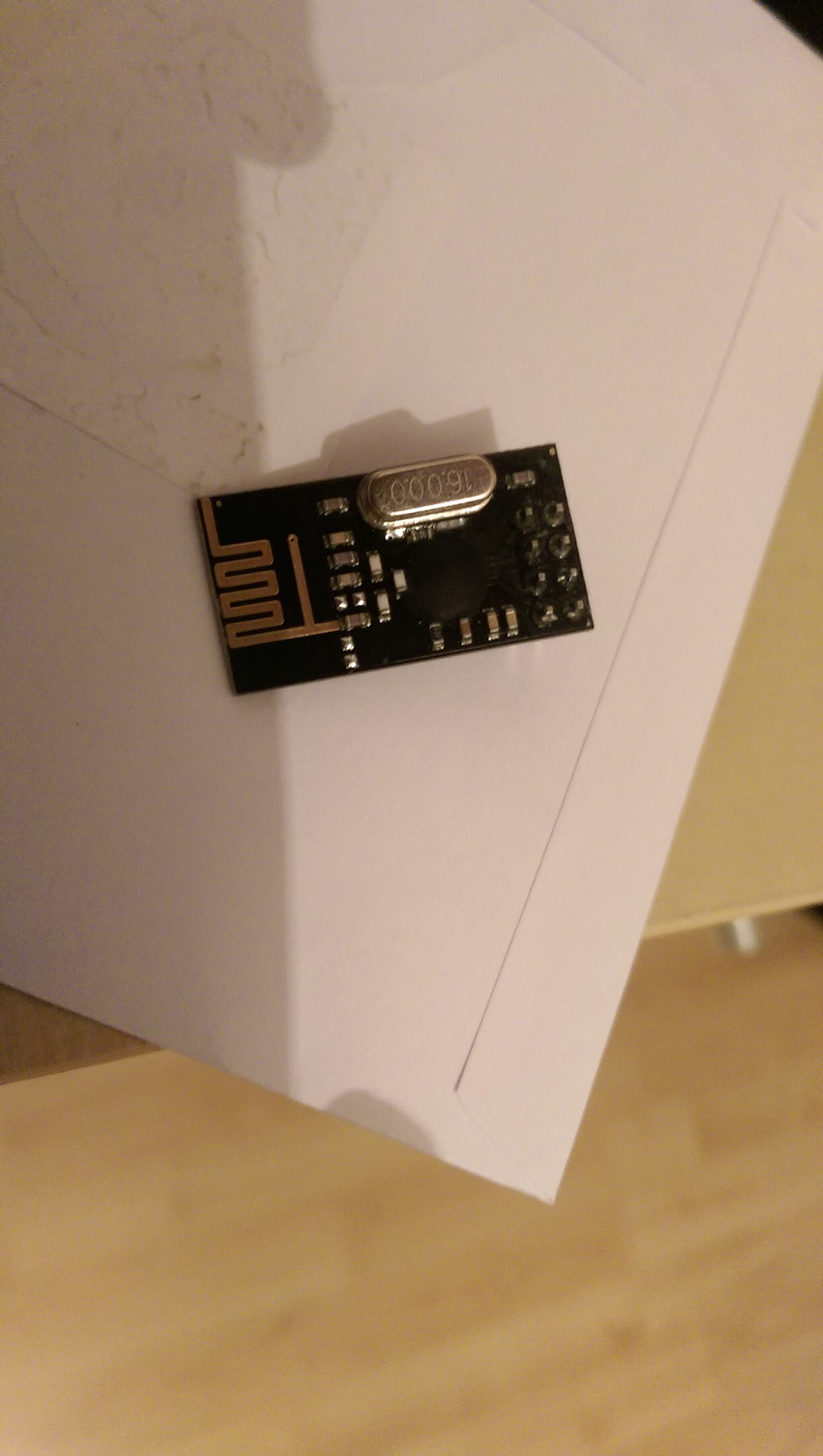
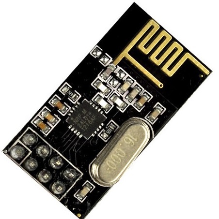
                    The chip on your looks like a blob more than this; You might have gotten a chinese ripoff .. I dont remember the chip name... Hmmmm hard to see!

                    edit:

                    maybe : http://forum.mysensors.org/topic/300/rfm73-experience/ ?
                    inverted CE?
                    nrf24L01-black.jpg

                    YveauxY RJ_MakeR 2 Replies Last reply
                    0
                    • DammeD Damme

                      @aquapro Hmmmm
                      The chip on your looks like a blob more than this; You might have gotten a chinese ripoff .. I dont remember the chip name... Hmmmm hard to see!

                      edit:

                      maybe : http://forum.mysensors.org/topic/300/rfm73-experience/ ?
                      inverted CE?

                      nrf24L01-black.jpg

                      YveauxY Offline
                      YveauxY Offline
                      Yveaux
                      Mod
                      wrote on last edited by Yveaux
                      #15

                      @Damme Sharp observation, dude!

                      Have a look at these: http://www.aliexpress.com/item/Free-shipping-10pcs-lot-NRF24L01-wireless-data-transmission-module-NRF24L01-wireless-module/1996222121.html

                      Claimed to be nRF24L01+!!

                      http://yveaux.blogspot.nl

                      1 Reply Last reply
                      0
                      • DammeD Damme

                        @aquapro Hmmmm
                        The chip on your looks like a blob more than this; You might have gotten a chinese ripoff .. I dont remember the chip name... Hmmmm hard to see!

                        edit:

                        maybe : http://forum.mysensors.org/topic/300/rfm73-experience/ ?
                        inverted CE?

                        nrf24L01-black.jpg

                        RJ_MakeR Offline
                        RJ_MakeR Offline
                        RJ_Make
                        Hero Member
                        wrote on last edited by
                        #16

                        @Damme
                        Nice Catch Indeed!

                        RJ_Make

                        1 Reply Last reply
                        0
                        • YveauxY Yveaux

                          @aquapro The MySensors site (http://www.mysensors.org/build/connect_radio) gives the following wiring:

                          Arduino     nRF24
                          9           CE
                          10          CSN
                          13          SCK
                          11          MOSI
                          12          MISO
                          2           IRQ
                          

                          These are the defaults for the library. CE & CSN you can adapt through the constructor of MySensor (did you do that?)

                          Looking at the pictures I have a hard time figuring out the connections for pins 8..12, while these are just the interesting part...

                          aquaproA Offline
                          aquaproA Offline
                          aquapro
                          wrote on last edited by aquapro
                          #17

                          @Yveaux yes I checked wiring with (http://www.mysensors.org/build/connect_radio)
                          more detail picture, hope so. (bad light)
                          IMAG0491.jpg

                          IMAG0493.jpg

                          @Damme
                          Chip is covered.
                          IMAG0494.jpg

                          1 Reply Last reply
                          0
                          • YveauxY Yveaux

                            @aquapro The MySensors site (http://www.mysensors.org/build/connect_radio) gives the following wiring:

                            Arduino     nRF24
                            9           CE
                            10          CSN
                            13          SCK
                            11          MOSI
                            12          MISO
                            2           IRQ
                            

                            These are the defaults for the library. CE & CSN you can adapt through the constructor of MySensor (did you do that?)

                            Looking at the pictures I have a hard time figuring out the connections for pins 8..12, while these are just the interesting part...

                            aquaproA Offline
                            aquaproA Offline
                            aquapro
                            wrote on last edited by
                            #18

                            @Yveaux

                            Looking at the pictures I have a hard time figuring out the connections for pins 8..12, while these are just the interesting part...

                            Pin 8?

                            YveauxY DammeD 2 Replies Last reply
                            0
                            • aquaproA aquapro

                              @Yveaux

                              Looking at the pictures I have a hard time figuring out the connections for pins 8..12, while these are just the interesting part...

                              Pin 8?

                              YveauxY Offline
                              YveauxY Offline
                              Yveaux
                              Mod
                              wrote on last edited by
                              #19

                              @aquapro said:

                              Pin 8?

                              It looked like you could have a connection to pin 8, but apparently (in the better pictures) you haven't...

                              http://yveaux.blogspot.nl

                              1 Reply Last reply
                              0
                              • aquaproA aquapro

                                @Yveaux

                                Looking at the pictures I have a hard time figuring out the connections for pins 8..12, while these are just the interesting part...

                                Pin 8?

                                DammeD Offline
                                DammeD Offline
                                Damme
                                Code Contributor
                                wrote on last edited by
                                #20

                                @aquapro I dont think you got a nordic semiconductor nrf24l01, What I can find they are only in QFN package.
                                http://www.nordicsemi.com/eng/Products/2.4GHz-RF/nRF24L01

                                So the specs on that chip may be different. Maybe CE is inverted?

                                1 Reply Last reply
                                0
                                • aquaproA Offline
                                  aquaproA Offline
                                  aquapro
                                  wrote on last edited by
                                  #21

                                  hm ... if CE inverted, ping sample should not work?! CE must switch between hight and low for TX and RX right? But Ping sample send and receive works.

                                  1 Reply Last reply
                                  0
                                  • aquaproA Offline
                                    aquaproA Offline
                                    aquapro
                                    wrote on last edited by
                                    #22

                                    Hi,

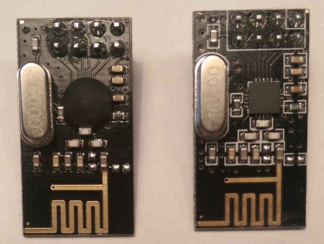
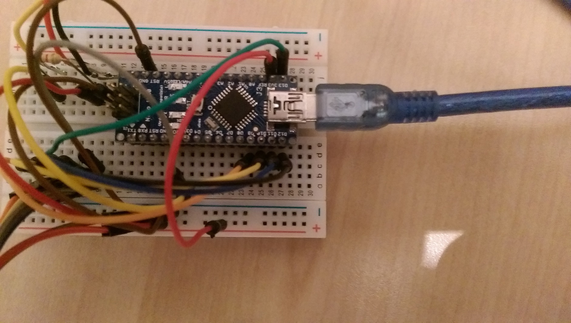
                                    I have bought the new modules (right on pic), which operate without modification. I simply swapped and all is fine.
                                    What do I do with the other. How can I test inverted.
                                    new.jpg

                                    hekH 1 Reply Last reply
                                    0
                                    • aquaproA aquapro

                                      Hi,

                                      I have bought the new modules (right on pic), which operate without modification. I simply swapped and all is fine.
                                      What do I do with the other. How can I test inverted.
                                      new.jpg

                                      hekH Offline
                                      hekH Offline
                                      hek
                                      Admin
                                      wrote on last edited by
                                      #23

                                      @aquapro

                                      I hope you didn't get the left one when purchasing through the links in the MySensors "store"?

                                      1 Reply Last reply
                                      0
                                      • aquaproA Offline
                                        aquaproA Offline
                                        aquapro
                                        wrote on last edited by
                                        #24

                                        I got the left one from other eb..-"store".

                                        1 Reply Last reply
                                        0
                                        • aquaproA Offline
                                          aquaproA Offline
                                          aquapro
                                          wrote on last edited by
                                          #25

                                          The left one works with MySensor-Coding, but only with disconnected CE line.

                                          1 Reply Last reply
                                          0
                                          Reply
                                          • Reply as topic
                                          Log in to reply
                                          • Oldest to Newest
                                          • Newest to Oldest
                                          • Most Votes


                                          17

                                          Online

                                          11.7k

                                          Users

                                          11.2k

                                          Topics

                                          113.0k

                                          Posts


                                          Copyright 2019 TBD   |   Forum Guidelines   |   Privacy Policy   |   Terms of Service
                                          • Login

                                          • Don't have an account? Register

                                          • Login or register to search.
                                          • First post
                                            Last post
                                          0
                                          • MySensors
                                          • OpenHardware.io
                                          • Categories
                                          • Recent
                                          • Tags
                                          • Popular