Skip to content
  • MySensors
  • OpenHardware.io
  • Categories
  • Recent
  • Tags
  • Popular
Skins
  • Light
  • Brite
  • Cerulean
  • Cosmo
  • Flatly
  • Journal
  • Litera
  • Lumen
  • Lux
  • Materia
  • Minty
  • Morph
  • Pulse
  • Sandstone
  • Simplex
  • Sketchy
  • Spacelab
  • United
  • Yeti
  • Zephyr
  • Dark
  • Cyborg
  • Darkly
  • Quartz
  • Slate
  • Solar
  • Superhero
  • Vapor

  • Default (No Skin)
  • No Skin
Collapse
Brand Logo
  1. Home
  2. Troubleshooting
  3. CE line on sensor node?

CE line on sensor node?

Scheduled Pinned Locked Moved Troubleshooting
29 Posts 6 Posters 9.9k Views 1 Watching
  • Oldest to Newest
  • Newest to Oldest
  • Most Votes
Reply
  • Reply as topic
Log in to reply
This topic has been deleted. Only users with topic management privileges can see it.
  • A aquapro

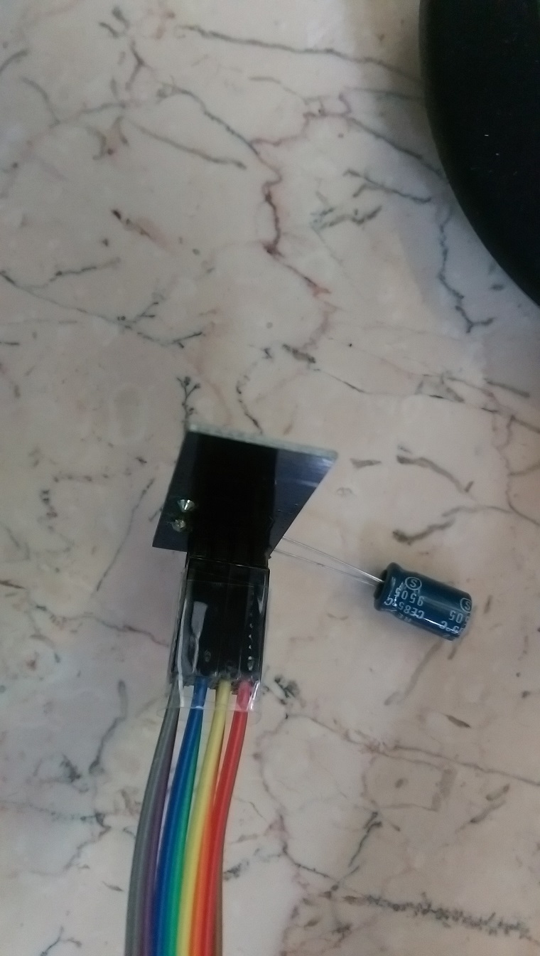
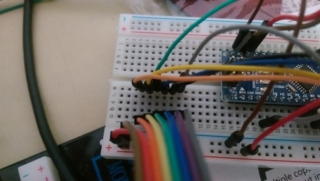
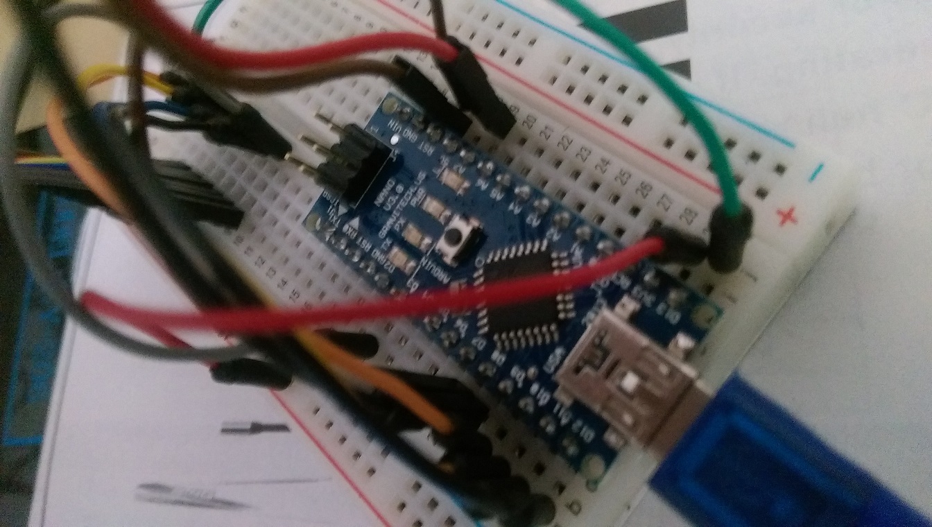
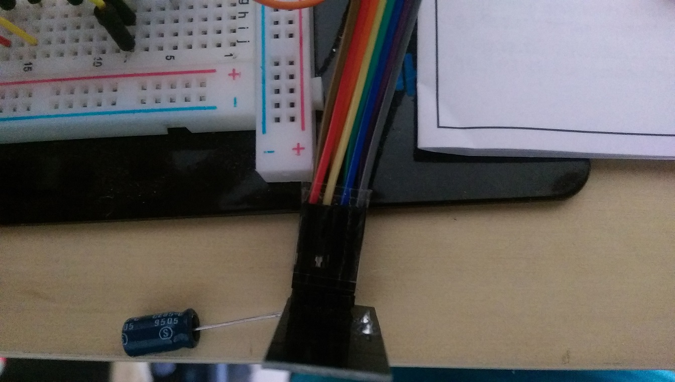
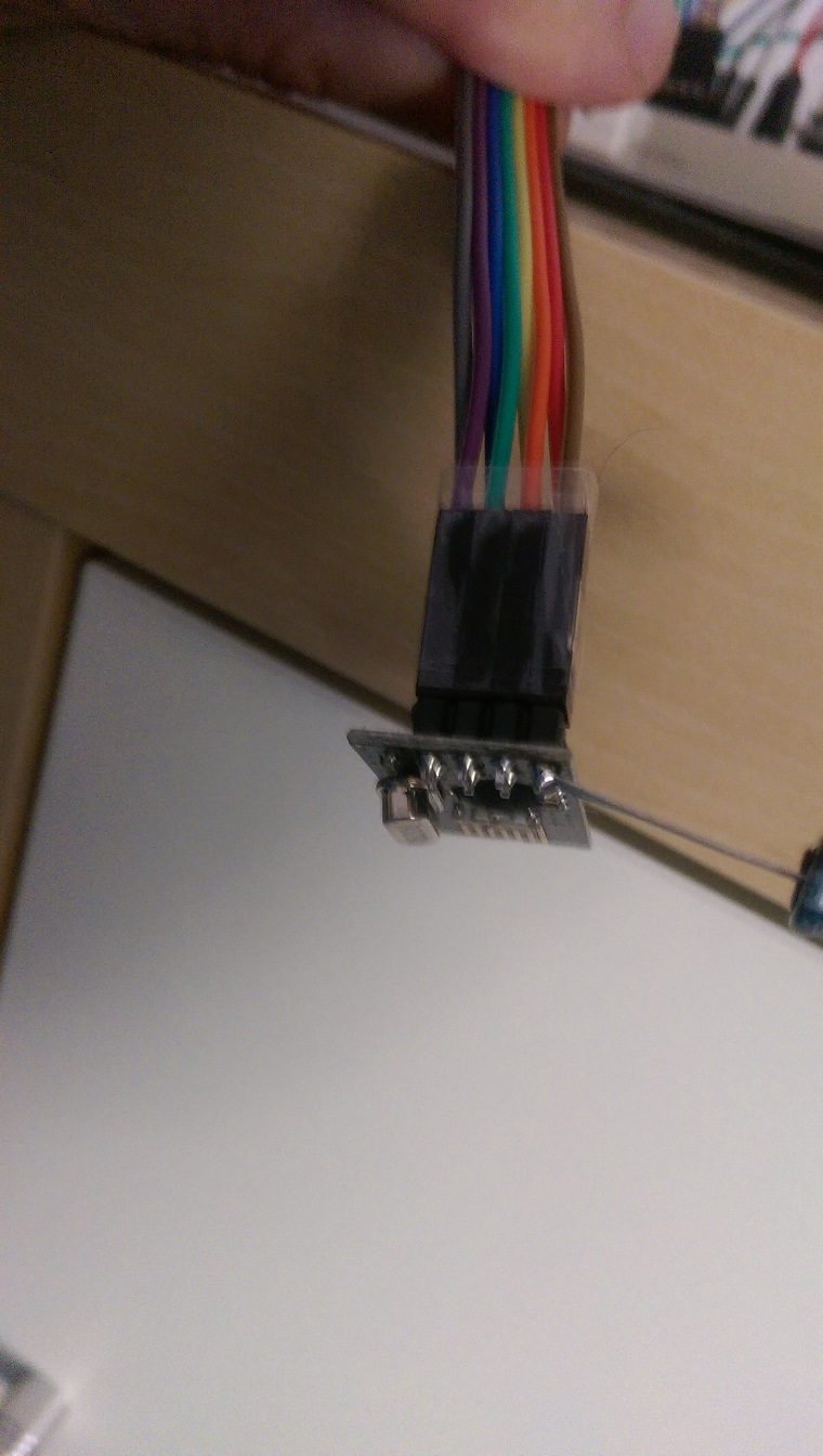
    If I disconnect orange wire (red marker on first sensor picture), sensor works fine.

    Sensor figures:
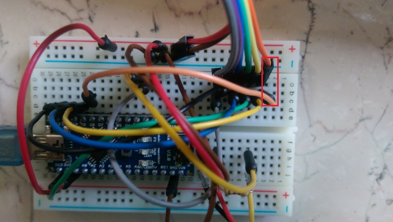
    IMAG0483a.jpg
    IMAG0484.jpg
    IMAG0485.jpg

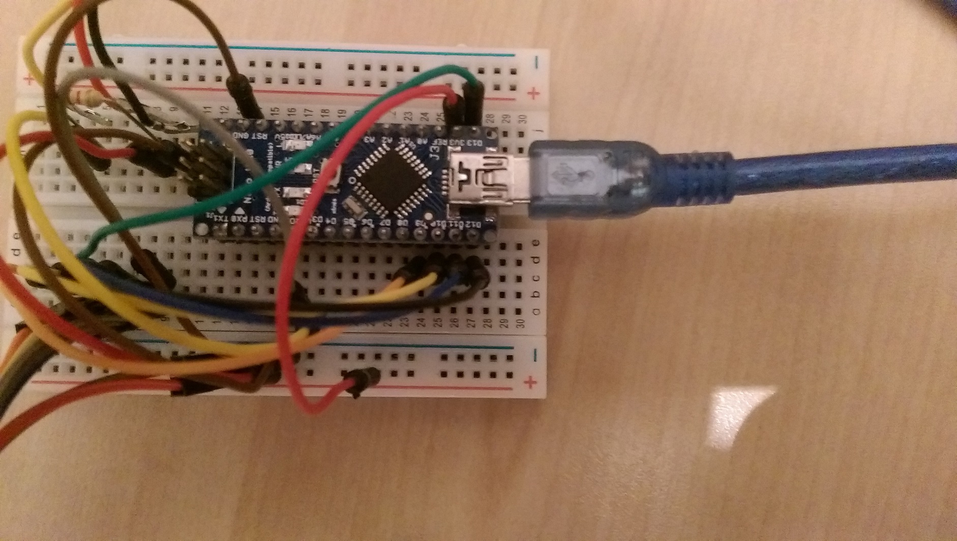
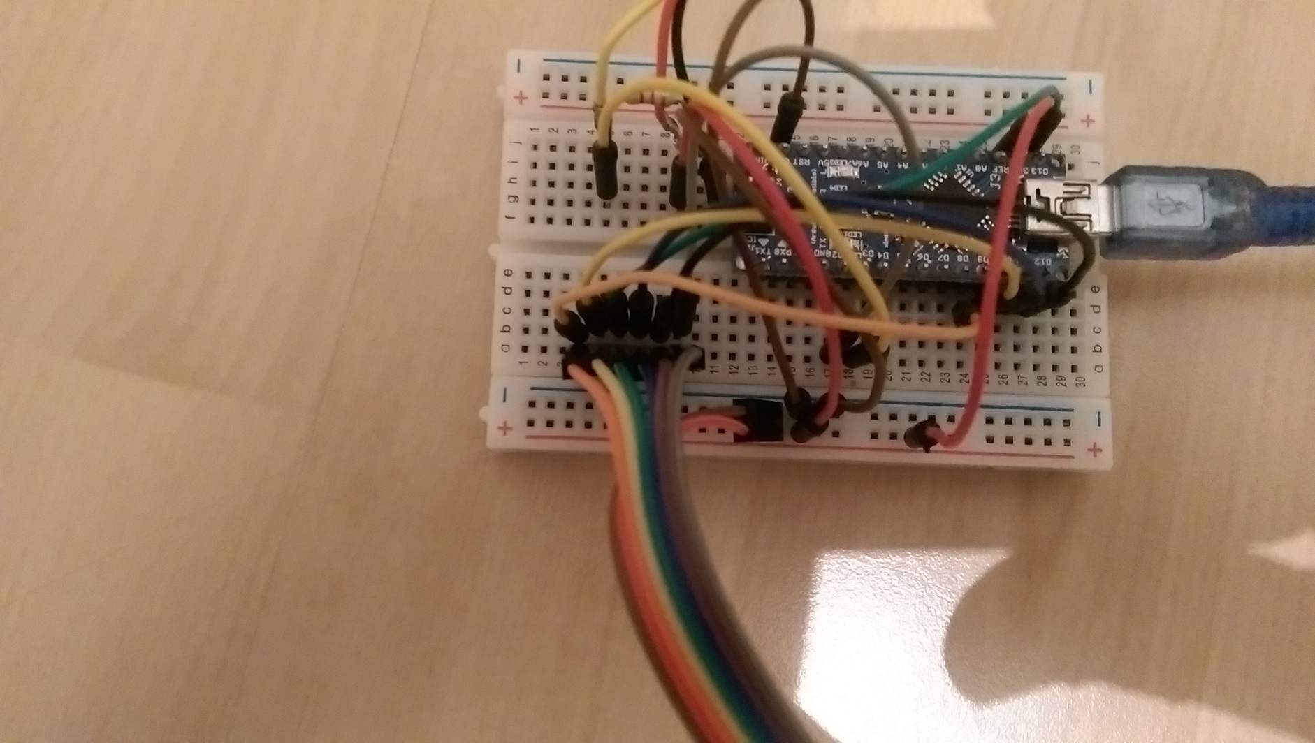
    Gateway figures:
    IMAG0486.jpg
    IMAG0487.jpg
    IMAG0488.jpg
    IMAG0490.jpg

    R Offline
    R Offline
    RJ_Make
    Hero Member
    wrote on last edited by
    #9

    @aquapro

    I think I would connected the radio directly to the breadboard pins next to the Arduino with new wiring.

    RJ_Make

    1 Reply Last reply
    0
    • A Offline
      A Offline
      aquapro
      wrote on last edited by
      #10

      @aquapro sagte:> Hi,

      I have tested 1000 times, wasted complete weekend. Rechecked with built up the wiring from scratch. Same Problem.
      Suppose I have swap the cables, which I doubt, why it works when I disconnect it completely?

      I have all the cables replaced, also new from different suppliers. I used the next pins on the Arduino. For the pictures I have to build something stretched to better overview.

      R 1 Reply Last reply
      0
      • A aquapro

        @aquapro sagte:> Hi,

        I have tested 1000 times, wasted complete weekend. Rechecked with built up the wiring from scratch. Same Problem.
        Suppose I have swap the cables, which I doubt, why it works when I disconnect it completely?

        I have all the cables replaced, also new from different suppliers. I used the next pins on the Arduino. For the pictures I have to build something stretched to better overview.

        R Offline
        R Offline
        RJ_Make
        Hero Member
        wrote on last edited by
        #11

        @aquapro
        So the pictures don't reflect the current wiring?

        RJ_Make

        1 Reply Last reply
        0
        • A Offline
          A Offline
          aquapro
          wrote on last edited by
          #12

          Pictures reflect the curren?t wiring! Same Problem with closer wiring

          1 Reply Last reply
          0
          • A aquapro

            If I disconnect orange wire (red marker on first sensor picture), sensor works fine.

            Sensor figures:
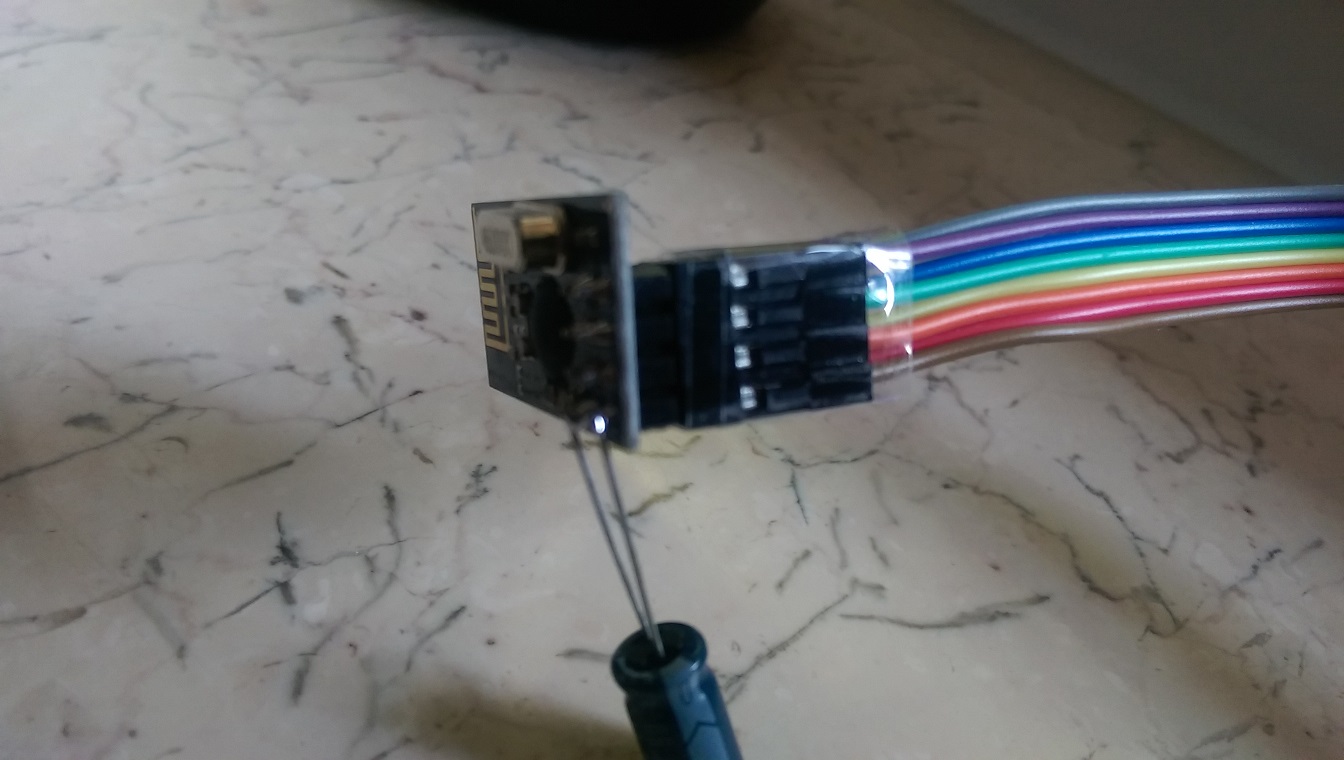
            IMAG0483a.jpg
            IMAG0484.jpg
            IMAG0485.jpg

            Gateway figures:
            IMAG0486.jpg
            IMAG0487.jpg
            IMAG0488.jpg
            IMAG0490.jpg

            Y Offline
            Y Offline
            Yveaux
            Mod
            wrote on last edited by
            #13

            @aquapro The MySensors site (http://www.mysensors.org/build/connect_radio) gives the following wiring:

            Arduino     nRF24
            9           CE
            10          CSN
            13          SCK
            11          MOSI
            12          MISO
            2           IRQ
            

            These are the defaults for the library. CE & CSN you can adapt through the constructor of MySensor (did you do that?)

            Looking at the pictures I have a hard time figuring out the connections for pins 8..12, while these are just the interesting part...

            http://yveaux.blogspot.nl

            A 2 Replies Last reply
            0
            • A aquapro

              hello,
              very good project!
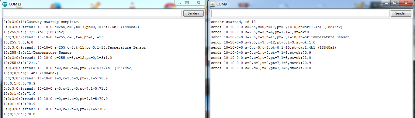
              I currently testing version 1.4b1 and I have a problem. Only if I disconnect the CE line on the sensor, the values ​​are transferred.
              If the CE line is connected, only one part will be sent, see Figure 1, the LED on the sensor remains on. As soon as I disconnect CE line, all values ​​are not sent are transmitted (Figure 2) and the LED goes out and lights up briefly in the next transmission.

              Does anyone have an idea?

              greeting

              aqua

              1_4_test_1.PNG
              Figure1

              1_4_test_1b.PNG
              Figure 2

              D Offline
              D Offline
              Damme
              Code Contributor
              wrote on last edited by Damme
              #14

              @aquapro Hmmmm
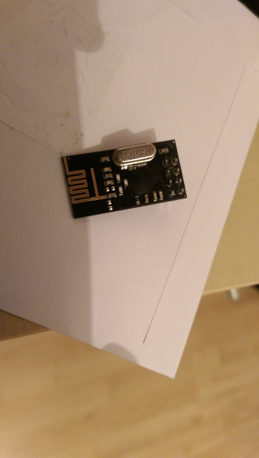
              The chip on your looks like a blob more than this; You might have gotten a chinese ripoff .. I dont remember the chip name... Hmmmm hard to see!

              edit:

              maybe : http://forum.mysensors.org/topic/300/rfm73-experience/ ?
              inverted CE?
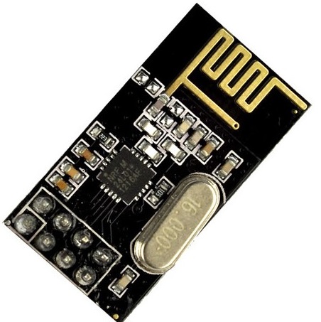
              nrf24L01-black.jpg

              Y R 2 Replies Last reply
              0
              • D Damme

                @aquapro Hmmmm
                The chip on your looks like a blob more than this; You might have gotten a chinese ripoff .. I dont remember the chip name... Hmmmm hard to see!

                edit:

                maybe : http://forum.mysensors.org/topic/300/rfm73-experience/ ?
                inverted CE?

                nrf24L01-black.jpg

                Y Offline
                Y Offline
                Yveaux
                Mod
                wrote on last edited by Yveaux
                #15

                @Damme Sharp observation, dude!

                Have a look at these: http://www.aliexpress.com/item/Free-shipping-10pcs-lot-NRF24L01-wireless-data-transmission-module-NRF24L01-wireless-module/1996222121.html

                Claimed to be nRF24L01+!!

                http://yveaux.blogspot.nl

                1 Reply Last reply
                0
                • D Damme

                  @aquapro Hmmmm
                  The chip on your looks like a blob more than this; You might have gotten a chinese ripoff .. I dont remember the chip name... Hmmmm hard to see!

                  edit:

                  maybe : http://forum.mysensors.org/topic/300/rfm73-experience/ ?
                  inverted CE?

                  nrf24L01-black.jpg

                  R Offline
                  R Offline
                  RJ_Make
                  Hero Member
                  wrote on last edited by
                  #16

                  @Damme
                  Nice Catch Indeed!

                  RJ_Make

                  1 Reply Last reply
                  0
                  • Y Yveaux

                    @aquapro The MySensors site (http://www.mysensors.org/build/connect_radio) gives the following wiring:

                    Arduino     nRF24
                    9           CE
                    10          CSN
                    13          SCK
                    11          MOSI
                    12          MISO
                    2           IRQ
                    

                    These are the defaults for the library. CE & CSN you can adapt through the constructor of MySensor (did you do that?)

                    Looking at the pictures I have a hard time figuring out the connections for pins 8..12, while these are just the interesting part...

                    A Offline
                    A Offline
                    aquapro
                    wrote on last edited by aquapro
                    #17

                    @Yveaux yes I checked wiring with (http://www.mysensors.org/build/connect_radio)
                    more detail picture, hope so. (bad light)
                    IMAG0491.jpg

                    IMAG0493.jpg

                    @Damme
                    Chip is covered.
                    IMAG0494.jpg

                    1 Reply Last reply
                    0
                    • Y Yveaux

                      @aquapro The MySensors site (http://www.mysensors.org/build/connect_radio) gives the following wiring:

                      Arduino     nRF24
                      9           CE
                      10          CSN
                      13          SCK
                      11          MOSI
                      12          MISO
                      2           IRQ
                      

                      These are the defaults for the library. CE & CSN you can adapt through the constructor of MySensor (did you do that?)

                      Looking at the pictures I have a hard time figuring out the connections for pins 8..12, while these are just the interesting part...

                      A Offline
                      A Offline
                      aquapro
                      wrote on last edited by
                      #18

                      @Yveaux

                      Looking at the pictures I have a hard time figuring out the connections for pins 8..12, while these are just the interesting part...

                      Pin 8?

                      Y D 2 Replies Last reply
                      0
                      • A aquapro

                        @Yveaux

                        Looking at the pictures I have a hard time figuring out the connections for pins 8..12, while these are just the interesting part...

                        Pin 8?

                        Y Offline
                        Y Offline
                        Yveaux
                        Mod
                        wrote on last edited by
                        #19

                        @aquapro said:

                        Pin 8?

                        It looked like you could have a connection to pin 8, but apparently (in the better pictures) you haven't...

                        http://yveaux.blogspot.nl

                        1 Reply Last reply
                        0
                        • A aquapro

                          @Yveaux

                          Looking at the pictures I have a hard time figuring out the connections for pins 8..12, while these are just the interesting part...

                          Pin 8?

                          D Offline
                          D Offline
                          Damme
                          Code Contributor
                          wrote on last edited by
                          #20

                          @aquapro I dont think you got a nordic semiconductor nrf24l01, What I can find they are only in QFN package.
                          http://www.nordicsemi.com/eng/Products/2.4GHz-RF/nRF24L01

                          So the specs on that chip may be different. Maybe CE is inverted?

                          1 Reply Last reply
                          0
                          • A Offline
                            A Offline
                            aquapro
                            wrote on last edited by
                            #21

                            hm ... if CE inverted, ping sample should not work?! CE must switch between hight and low for TX and RX right? But Ping sample send and receive works.

                            1 Reply Last reply
                            0
                            • A Offline
                              A Offline
                              aquapro
                              wrote on last edited by
                              #22

                              Hi,

                              I have bought the new modules (right on pic), which operate without modification. I simply swapped and all is fine.
                              What do I do with the other. How can I test inverted.
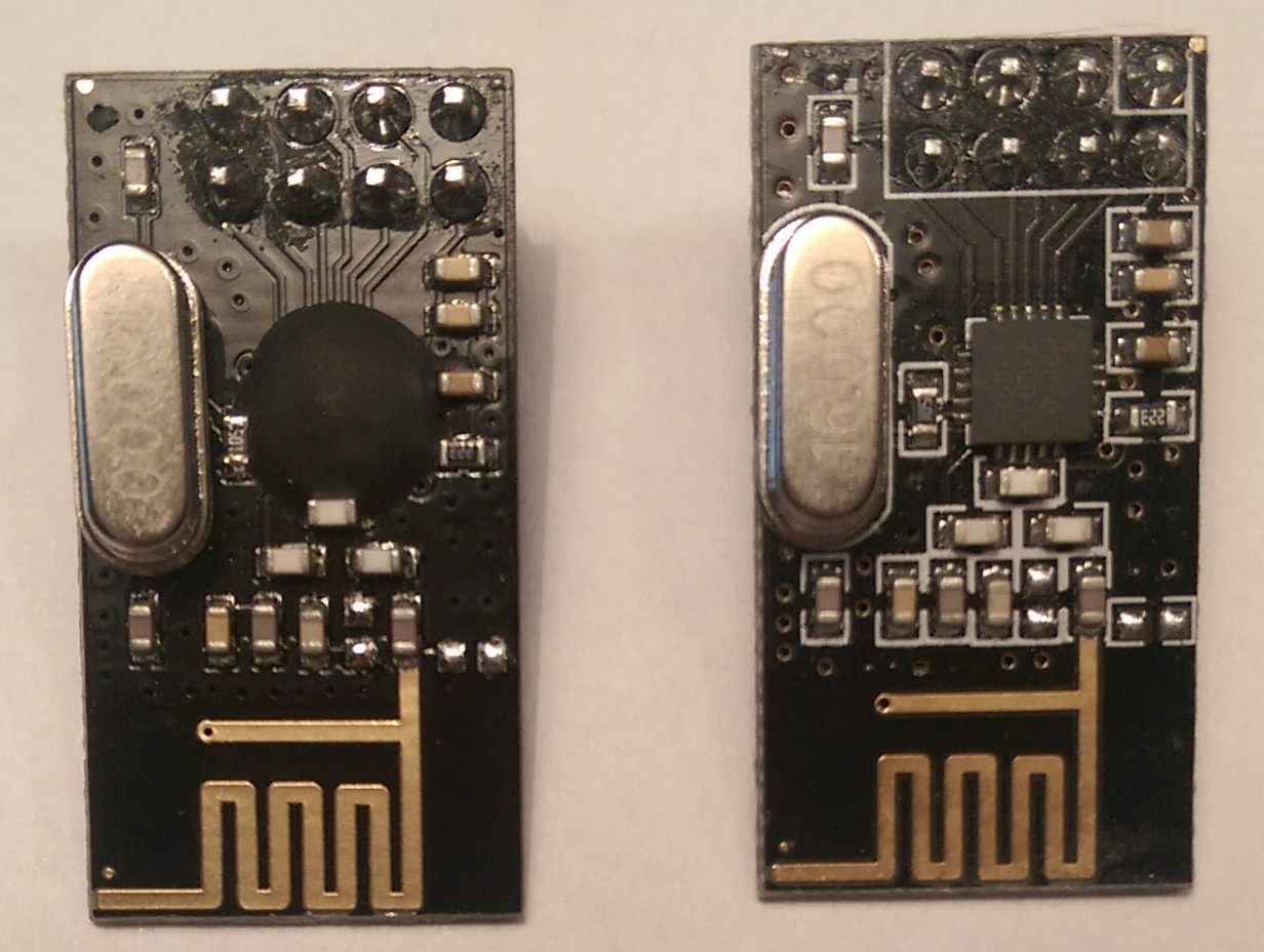
                              new.jpg

                              H 1 Reply Last reply
                              0
                              • A aquapro

                                Hi,

                                I have bought the new modules (right on pic), which operate without modification. I simply swapped and all is fine.
                                What do I do with the other. How can I test inverted.

                                new.jpg

                                H Offline
                                H Offline
                                hek
                                Admin
                                wrote on last edited by
                                #23

                                @aquapro

                                I hope you didn't get the left one when purchasing through the links in the MySensors "store"?

                                1 Reply Last reply
                                0
                                • A Offline
                                  A Offline
                                  aquapro
                                  wrote on last edited by
                                  #24

                                  I got the left one from other eb..-"store".

                                  1 Reply Last reply
                                  0
                                  • A Offline
                                    A Offline
                                    aquapro
                                    wrote on last edited by
                                    #25

                                    The left one works with MySensor-Coding, but only with disconnected CE line.

                                    1 Reply Last reply
                                    0
                                    • Z Offline
                                      Z Offline
                                      Zeph
                                      Hero Member
                                      wrote on last edited by
                                      #26

                                      If it truly works correctly with CE disconnected, that could be an advantage when there is a shortage of pins (eg: 8 pin ATTiny).

                                      Have you achieved full operation without CE on the old modules?

                                      And did you leave CE floating or tie it high?

                                      1 Reply Last reply
                                      0
                                      • A Offline
                                        A Offline
                                        aquapro
                                        wrote on last edited by
                                        #27

                                        I still see no difference when CE is disconnected.Only it as work at all.

                                        1 Reply Last reply
                                        0
                                        • Z Offline
                                          Z Offline
                                          Zeph
                                          Hero Member
                                          wrote on last edited by
                                          #28

                                          What vendor did you use to get the "no CE needed" variants? That could be useful to test.

                                          I'm assuming that the nRF24L01+ doesn't work without CE connected, right?

                                          1 Reply Last reply
                                          0

                                          Hello! It looks like you're interested in this conversation, but you don't have an account yet.

                                          Getting fed up of having to scroll through the same posts each visit? When you register for an account, you'll always come back to exactly where you were before, and choose to be notified of new replies (either via email, or push notification). You'll also be able to save bookmarks and upvote posts to show your appreciation to other community members.

                                          With your input, this post could be even better 💗

                                          Register Login
                                          Reply
                                          • Reply as topic
                                          Log in to reply
                                          • Oldest to Newest
                                          • Newest to Oldest
                                          • Most Votes


                                          70

                                          Online

                                          12.0k

                                          Users

                                          11.2k

                                          Topics

                                          113.4k

                                          Posts


                                          Copyright 2025 TBD   |   Forum Guidelines   |   Privacy Policy   |   Terms of Service
                                          • Login

                                          • Don't have an account? Register

                                          • Login or register to search.
                                          • First post
                                            Last post
                                          0
                                          • MySensors
                                          • OpenHardware.io
                                          • Categories
                                          • Recent
                                          • Tags
                                          • Popular