Door sensor Radio OK !TSM:FAILURE
-
Hi i made a door sensor with this exemple : https://www.mysensors.org/build/binary
And the log always give me this :
Starting sensor (RNNNA-, 2.0.0) TSM:INIT TSM:RADIO:OK !TSP:ASSIGNID:FAIL (ID=0) !TSM:FAILURE TSM:PDT TSM:FPAR TSP:MSG:SEND 0-0-255-255 s=255,c=3,t=7,pt=0,l=0,sg=0,ft=0,st=bc: TSM:FPAR TSP:MSG:SEND 0-0-255-255 s=255,c=3,t=7,pt=0,l=0,sg=0,ft=0,st=bc: TSM:FPAR TSP:MSG:SEND 0-0-255-255 s=255,c=3,t=7,pt=0,l=0,sg=0,ft=0,st=bc: TSM:FPAR TSP:MSG:SEND 0-0-255-255 s=255,c=3,t=7,pt=0,l=0,sg=0,ft=0,st=bc: -
Hi i made a door sensor with this exemple : https://www.mysensors.org/build/binary
And the log always give me this :
Starting sensor (RNNNA-, 2.0.0) TSM:INIT TSM:RADIO:OK !TSP:ASSIGNID:FAIL (ID=0) !TSM:FAILURE TSM:PDT TSM:FPAR TSP:MSG:SEND 0-0-255-255 s=255,c=3,t=7,pt=0,l=0,sg=0,ft=0,st=bc: TSM:FPAR TSP:MSG:SEND 0-0-255-255 s=255,c=3,t=7,pt=0,l=0,sg=0,ft=0,st=bc: TSM:FPAR TSP:MSG:SEND 0-0-255-255 s=255,c=3,t=7,pt=0,l=0,sg=0,ft=0,st=bc: TSM:FPAR TSP:MSG:SEND 0-0-255-255 s=255,c=3,t=7,pt=0,l=0,sg=0,ft=0,st=bc:@Dominic-Bonneau See my response to this thread: https://forum.mysensors.org/topic/4515/first-tries-with-mysensors-v2-0-problem-staring-up/2
I guess you also assigned an illegal node ID. -
Ok set I manualy set my ID to 2 and now a got the :
Starting sensor (RNNNA-, 2.0.0) TSM:INIT TSM:RADIO:OK TSP:ASSIGNID:OK (ID=2) TSM:FPAR TSP:MSG:SEND 2-2-255-255 s=255,c=3,t=7,pt=0,l=0,sg=0,ft=0,st=bc: TSM:FPAR TSP:MSG:SEND 2-2-255-255 s=255,c=3,t=7,pt=0,l=0,sg=0,ft=0,st=bc: TSM:FPAR TSP:MSG:SEND 2-2-255-255 s=255,c=3,t=7,pt=0,l=0,sg=0,ft=0,st=bc: TSM:FPAR TSP:MSG:SEND 2-2-255-255 s=255,c=3,t=7,pt=0,l=0,sg=0,ft=0,st=bc: !TSM:FPAR:FAIL !TSM:FAILURE TSM:PDT -
Ok set I manualy set my ID to 2 and now a got the :
Starting sensor (RNNNA-, 2.0.0) TSM:INIT TSM:RADIO:OK TSP:ASSIGNID:OK (ID=2) TSM:FPAR TSP:MSG:SEND 2-2-255-255 s=255,c=3,t=7,pt=0,l=0,sg=0,ft=0,st=bc: TSM:FPAR TSP:MSG:SEND 2-2-255-255 s=255,c=3,t=7,pt=0,l=0,sg=0,ft=0,st=bc: TSM:FPAR TSP:MSG:SEND 2-2-255-255 s=255,c=3,t=7,pt=0,l=0,sg=0,ft=0,st=bc: TSM:FPAR TSP:MSG:SEND 2-2-255-255 s=255,c=3,t=7,pt=0,l=0,sg=0,ft=0,st=bc: !TSM:FPAR:FAIL !TSM:FAILURE TSM:PDT@Dominic-Bonneau can you post your sketch? It's hard to help without it
-
Ok set I manualy set my ID to 2 and now a got the :
Starting sensor (RNNNA-, 2.0.0) TSM:INIT TSM:RADIO:OK TSP:ASSIGNID:OK (ID=2) TSM:FPAR TSP:MSG:SEND 2-2-255-255 s=255,c=3,t=7,pt=0,l=0,sg=0,ft=0,st=bc: TSM:FPAR TSP:MSG:SEND 2-2-255-255 s=255,c=3,t=7,pt=0,l=0,sg=0,ft=0,st=bc: TSM:FPAR TSP:MSG:SEND 2-2-255-255 s=255,c=3,t=7,pt=0,l=0,sg=0,ft=0,st=bc: TSM:FPAR TSP:MSG:SEND 2-2-255-255 s=255,c=3,t=7,pt=0,l=0,sg=0,ft=0,st=bc: !TSM:FPAR:FAIL !TSM:FAILURE TSM:PDT -
Oups... Yeah my bad I was trying something with not the same library of my gateway.
This is the sketch :
/**
 * The MySensors Arduino library handles the wireless radio link and protocol
 * between your home built sensors/actuators and HA controller of choice.
 * The sensors forms a self healing radio network with optional repeaters. Each
 * repeater and gateway builds a routing tables in EEPROM which keeps track of the
 * network topology allowing messages to be routed to nodes.
 *
 * Created by Henrik Ekblad <henrik.ekblad@mysensors.org>
 * Copyright (C) 2013-2015 Sensnology AB
 * Full contributor list: https://github.com/mysensors/Arduino/graphs/contributors
 *
 * Documentation: http://www.mysensors.org
 * Support Forum: http://forum.mysensors.org
 *
 * This program is free software; you can redistribute it and/or
 * modify it under the terms of the GNU General Public License
 * version 2 as published by the Free Software Foundation.
 *
 *******************************
 *
 * DESCRIPTION
 *
 * Interrupt driven binary switch example with dual interrupts
 * Author: Patrick 'Anticimex' Fallberg
 * Connect one button or door/window reed switch between
 * digitial I/O pin 3 (BUTTON_PIN below) and GND and the other
 * one in similar fashion on digital I/O pin 2.
 * This example is designed to fit Arduino Nano/Pro Mini
 *
 */


// Enable debug prints to serial monitor
#define MY_DEBUG

// Enable and select radio type attached
#define MY_RADIO_NRF24
//#define MY_RADIO_RFM69

#include <SPI.h>
#include <MySensors.h>

#define SKETCH_NAME "Binary Sensor"
#define SKETCH_MAJOR_VER "1"
#define SKETCH_MINOR_VER "0"

#define PRIMARY_CHILD_ID 3
#define SECONDARY_CHILD_ID 4

#define PRIMARY_BUTTON_PIN 2   // Arduino Digital I/O pin for button/reed switch
#define SECONDARY_BUTTON_PIN 3 // Arduino Digital I/O pin for button/reed switch

#if (PRIMARY_BUTTON_PIN < 2 || PRIMARY_BUTTON_PIN > 3)
#error PRIMARY_BUTTON_PIN must be either 2 or 3 for interrupts to work
#endif
#if (SECONDARY_BUTTON_PIN < 2 || SECONDARY_BUTTON_PIN > 3)
#error SECONDARY_BUTTON_PIN must be either 2 or 3 for interrupts to work
#endif
#if (PRIMARY_BUTTON_PIN == SECONDARY_BUTTON_PIN)
#error PRIMARY_BUTTON_PIN and BUTTON_PIN2 cannot be the same
#endif
#if (PRIMARY_CHILD_ID == SECONDARY_CHILD_ID)
#error PRIMARY_CHILD_ID and SECONDARY_CHILD_ID cannot be the same
#endif


// Change to V_LIGHT if you use S_LIGHT in presentation below
MyMessage msg(PRIMARY_CHILD_ID, V_TRIPPED);
MyMessage msg2(SECONDARY_CHILD_ID, V_TRIPPED);

void setup()
{
  // Setup the buttons
  pinMode(PRIMARY_BUTTON_PIN, INPUT);
  pinMode(SECONDARY_BUTTON_PIN, INPUT);

  // Activate internal pull-ups
  digitalWrite(PRIMARY_BUTTON_PIN, HIGH);
  digitalWrite(SECONDARY_BUTTON_PIN, HIGH);
}

void presentation() {
  // Send the sketch version information to the gateway and Controller
  sendSketchInfo(SKETCH_NAME, SKETCH_MAJOR_VER "." SKETCH_MINOR_VER);

  // Register binary input sensor to sensor_node (they will be created as child devices)
  // You can use S_DOOR, S_MOTION or S_LIGHT here depending on your usage.
  // If S_LIGHT is used, remember to update variable type you send in. See "msg" above.
  present(PRIMARY_CHILD_ID, S_DOOR);
  present(SECONDARY_CHILD_ID, S_DOOR);
}

// Loop will iterate on changes on the BUTTON_PINs
void loop()
{
  uint8_t value;
  static uint8_t sentValue=2;
  static uint8_t sentValue2=2;

  // Short delay to allow buttons to properly settle
  sleep(5);

  value = digitalRead(PRIMARY_BUTTON_PIN);

  if (value != sentValue) {
     // Value has changed from last transmission, send the updated value
     send(msg.set(value==HIGH ? 1 : 0));
     sentValue = value;
  }

  value = digitalRead(SECONDARY_BUTTON_PIN);

  if (value != sentValue2) {
     // Value has changed from last transmission, send the updated value
     send(msg2.set(value==HIGH ? 1 : 0));
     sentValue2 = value;
  }

  // Sleep until something happens with the sensor
  sleep(PRIMARY_BUTTON_PIN-2, CHANGE, SECONDARY_BUTTON_PIN-2, CHANGE, 0);
}
And this is the log :
MCO:BGN:INIT NODE,CP=RNNNA--,VER=2.0.1-beta
TSM:INIT
TSM:INIT:TSP OK
TSF:ASID:OK,ID=2
TSM:FPAR
TSF:MSG:SEND,2-2-255-255,s=255,c=3,t=7,pt=0,l=0,sg=0,ft=0,st=bc:
!TSM:FPAR:NO REPLY
TSM:FPAR
TSF:MSG:SEND,2-2-255-255,s=255,c=3,t=7,pt=0,l=0,sg=0,ft=0,st=bc:
!TSM:FPAR:NO REPLY
TSM:FPAR
TSF:MSG:SEND,2-2-255-255,s=255,c=3,t=7,pt=0,l=0,sg=0,ft=0,st=bc:
!TSM:FPAR:NO REPLY
TSM:FPAR
TSF:MSG:SEND,2-2-255-255,s=255,c=3,t=7,pt=0,l=0,sg=0,ft=0,st=bc:
!TSM:FPAR:FAIL
TSM:FAILURE
TSM:FAILURE:PDT
I don’t know why he said no reply my gateway is in 2.0.1 like my sensor. I can ping it .. And receive data from my gateway on my mqtt broker …
-
This post is deleted!
-
Oups... Yeah my bad I was trying something with not the same library of my gateway.
This is the sketch :
/**
 * The MySensors Arduino library handles the wireless radio link and protocol
 * between your home built sensors/actuators and HA controller of choice.
 * The sensors forms a self healing radio network with optional repeaters. Each
 * repeater and gateway builds a routing tables in EEPROM which keeps track of the
 * network topology allowing messages to be routed to nodes.
 *
 * Created by Henrik Ekblad <henrik.ekblad@mysensors.org>
 * Copyright (C) 2013-2015 Sensnology AB
 * Full contributor list: https://github.com/mysensors/Arduino/graphs/contributors
 *
 * Documentation: http://www.mysensors.org
 * Support Forum: http://forum.mysensors.org
 *
 * This program is free software; you can redistribute it and/or
 * modify it under the terms of the GNU General Public License
 * version 2 as published by the Free Software Foundation.
 *
 *******************************
 *
 * DESCRIPTION
 *
 * Interrupt driven binary switch example with dual interrupts
 * Author: Patrick 'Anticimex' Fallberg
 * Connect one button or door/window reed switch between
 * digitial I/O pin 3 (BUTTON_PIN below) and GND and the other
 * one in similar fashion on digital I/O pin 2.
 * This example is designed to fit Arduino Nano/Pro Mini
 *
 */


// Enable debug prints to serial monitor
#define MY_DEBUG

// Enable and select radio type attached
#define MY_RADIO_NRF24
//#define MY_RADIO_RFM69

#include <SPI.h>
#include <MySensors.h>

#define SKETCH_NAME "Binary Sensor"
#define SKETCH_MAJOR_VER "1"
#define SKETCH_MINOR_VER "0"

#define PRIMARY_CHILD_ID 3
#define SECONDARY_CHILD_ID 4

#define PRIMARY_BUTTON_PIN 2   // Arduino Digital I/O pin for button/reed switch
#define SECONDARY_BUTTON_PIN 3 // Arduino Digital I/O pin for button/reed switch

#if (PRIMARY_BUTTON_PIN < 2 || PRIMARY_BUTTON_PIN > 3)
#error PRIMARY_BUTTON_PIN must be either 2 or 3 for interrupts to work
#endif
#if (SECONDARY_BUTTON_PIN < 2 || SECONDARY_BUTTON_PIN > 3)
#error SECONDARY_BUTTON_PIN must be either 2 or 3 for interrupts to work
#endif
#if (PRIMARY_BUTTON_PIN == SECONDARY_BUTTON_PIN)
#error PRIMARY_BUTTON_PIN and BUTTON_PIN2 cannot be the same
#endif
#if (PRIMARY_CHILD_ID == SECONDARY_CHILD_ID)
#error PRIMARY_CHILD_ID and SECONDARY_CHILD_ID cannot be the same
#endif


// Change to V_LIGHT if you use S_LIGHT in presentation below
MyMessage msg(PRIMARY_CHILD_ID, V_TRIPPED);
MyMessage msg2(SECONDARY_CHILD_ID, V_TRIPPED);

void setup()
{
  // Setup the buttons
  pinMode(PRIMARY_BUTTON_PIN, INPUT);
  pinMode(SECONDARY_BUTTON_PIN, INPUT);

  // Activate internal pull-ups
  digitalWrite(PRIMARY_BUTTON_PIN, HIGH);
  digitalWrite(SECONDARY_BUTTON_PIN, HIGH);
}

void presentation() {
  // Send the sketch version information to the gateway and Controller
  sendSketchInfo(SKETCH_NAME, SKETCH_MAJOR_VER "." SKETCH_MINOR_VER);

  // Register binary input sensor to sensor_node (they will be created as child devices)
  // You can use S_DOOR, S_MOTION or S_LIGHT here depending on your usage.
  // If S_LIGHT is used, remember to update variable type you send in. See "msg" above.
  present(PRIMARY_CHILD_ID, S_DOOR);
  present(SECONDARY_CHILD_ID, S_DOOR);
}

// Loop will iterate on changes on the BUTTON_PINs
void loop()
{
  uint8_t value;
  static uint8_t sentValue=2;
  static uint8_t sentValue2=2;

  // Short delay to allow buttons to properly settle
  sleep(5);

  value = digitalRead(PRIMARY_BUTTON_PIN);

  if (value != sentValue) {
     // Value has changed from last transmission, send the updated value
     send(msg.set(value==HIGH ? 1 : 0));
     sentValue = value;
  }

  value = digitalRead(SECONDARY_BUTTON_PIN);

  if (value != sentValue2) {
     // Value has changed from last transmission, send the updated value
     send(msg2.set(value==HIGH ? 1 : 0));
     sentValue2 = value;
  }

  // Sleep until something happens with the sensor
  sleep(PRIMARY_BUTTON_PIN-2, CHANGE, SECONDARY_BUTTON_PIN-2, CHANGE, 0);
}
And this is the log :
MCO:BGN:INIT NODE,CP=RNNNA--,VER=2.0.1-beta
TSM:INIT
TSM:INIT:TSP OK
TSF:ASID:OK,ID=2
TSM:FPAR
TSF:MSG:SEND,2-2-255-255,s=255,c=3,t=7,pt=0,l=0,sg=0,ft=0,st=bc:
!TSM:FPAR:NO REPLY
TSM:FPAR
TSF:MSG:SEND,2-2-255-255,s=255,c=3,t=7,pt=0,l=0,sg=0,ft=0,st=bc:
!TSM:FPAR:NO REPLY
TSM:FPAR
TSF:MSG:SEND,2-2-255-255,s=255,c=3,t=7,pt=0,l=0,sg=0,ft=0,st=bc:
!TSM:FPAR:NO REPLY
TSM:FPAR
TSF:MSG:SEND,2-2-255-255,s=255,c=3,t=7,pt=0,l=0,sg=0,ft=0,st=bc:
!TSM:FPAR:FAIL
TSM:FAILURE
TSM:FAILURE:PDT
I don’t know why he said no reply my gateway is in 2.0.1 like my sensor. I can ping it .. And receive data from my gateway on my mqtt broker …
@Dominic-Bonneau said:
I don’t know why he said no reply my gateway is in 2.0.1 like my sensor. I can ping it .. And receive data from my gateway on my mqtt broker …
Can you provide a more detailed log showing what you describe? (Ideally of both, GW and node). Thanks
-
I can I have a more detailed log ?
-
I can I have a more detailed log ?
-
For the sensor it's repeating the something over and over ....
For the Gateway I got this :
0;255;3;0;9;MCO:BGN:INIT GW,CP=RNNGA--,VER=2.0.1-beta 0;255;3;0;9;TSM:INIT 0;255;3;0;9;TSM:INIT:TSP OK 0;255;3;0;9;TSM:INIT:GW MODE 0;255;3;0;9;TSM:READY IP: 192.168.111.6 0;255;3;0;9;MCO:REG:NOT NEEDED 0;255;3;0;9;MCO:BGN:INIT OK,ID=0,PAR=0,DIS=0,REG=1 IP: 192.168.111.6 0;255;3;0;9;Attempting MQTT connection... 0;255;3;0;9;MQTT connected 0;255;3;0;9;Sending message on topic: mygateway1-out/0/255/0/0/18 0;255;3;0;9;TSF:SANCHK:OK 0;255;3;0;9;TSF:SANCHK:OK 0;255;3;0;9;TSF:SANCHK:OK 0;255;3;0;9;TSF:SANCHK:OK 0;255;3;0;9;TSF:SANCHK:OK 0;255;3;0;9;TSF:SANCHK:OK 0;255;3;0;9;TSF:SANCHK:OK 0;255;3;0;9;TSF:SANCHK:OK 0;255;3;0;9;TSF:SANCHK:OK 0;255;3;0;9;TSF:SANCHK:OK 0;255;3;0;9;TSF:SANCHK:OK 0;255;3;0;9;TSF:SANCHK:OK 0;255;3;0;9;TSF:SANCHK:OK 0;255;3;0;9;TSF:SANCHK:OK 0;255;3;0;9;TSF:SANCHK:OK 0;255;3;0;9;TSF:SANCHK:OK 0;255;3;0;9;TSF:SANCHK:OK 0;255;3;0;9;TSF:SANCHK:OK 0;255;3;0;9;TSF:SANCHK:OK 0;255;3;0;9;TSF:SANCHK:OK 0;255;3;0;9;TSF:SANCHK:OK 0;255;3;0;9;TSF:SANCHK:OK 0;255;3;0;9;TSF:SANCHK:OK 0;255;3;0;9;TSF:SANCHK:OK 0;255;3;0;9;TSF:SANCHK:OK 0;255;3;0;9;TSF:SANCHK:OK 0;255;3;0;9;TSF:SANCHK:OK 0;255;3;0;9;TSF:SANCHK:OK 0;255;3;0;9;TSF:SANCHK:OK 0;255;3;0;9;TSF:SANCHK:OK 0;255;3;0;9;TSF:SANCHK:OK 0;255;3;0;9;TSF:SANCHK:OK -
Ok so i'm still not able to make it work...
My gateway is an arduino uno and my node a mini pro 3.3v 8mhz ...
i don't have anny capacitor for the radio and i could pass this afternoon at an electronic store...
do i need one for my gateway AND my node ?
on the my sensor web site they recommand 47µF but on the forum i saw at some place that i should use 100µF
??
-
Ok so i'm still not able to make it work...
My gateway is an arduino uno and my node a mini pro 3.3v 8mhz ...
i don't have anny capacitor for the radio and i could pass this afternoon at an electronic store...
do i need one for my gateway AND my node ?
on the my sensor web site they recommand 47µF but on the forum i saw at some place that i should use 100µF
??
@Dominic-Bonneau you'll need one capacitor for each radio. So in your case two, one for the gateway and one for the node.
I hear some people use a 47uF others a 100uF. Since I've hear no complaints about the 100uF I'd use a 100uF. The bigger means in these case, that the capacitor can store a bit more power. If you're not sure buy two of both. They're really cheap - at least they should be.
-
@Dominic-Bonneau you'll need one capacitor for each radio. So in your case two, one for the gateway and one for the node.
I hear some people use a 47uF others a 100uF. Since I've hear no complaints about the 100uF I'd use a 100uF. The bigger means in these case, that the capacitor can store a bit more power. If you're not sure buy two of both. They're really cheap - at least they should be.
@TheoL , Indeed. I use 47uF and 100uF , just the first one I grab out of the spare tool box ;-) I use them with my NANO's and Rf24 antenna.
Ow yes, and I power all from the NANO ;-)As long as I don't add the LED FLASH and the external big antenna
I'm fine. If I use the external antenna with LED FLASH... no way that it works.
If I just use the external antenna without LED FLASH there is enough power in the capacitor to help the antenna do its thing ;-0 -
@TheoL , Indeed. I use 47uF and 100uF , just the first one I grab out of the spare tool box ;-) I use them with my NANO's and Rf24 antenna.
Ow yes, and I power all from the NANO ;-)As long as I don't add the LED FLASH and the external big antenna
I'm fine. If I use the external antenna with LED FLASH... no way that it works.
If I just use the external antenna without LED FLASH there is enough power in the capacitor to help the antenna do its thing ;-0@sincze Hello my friend.
If you want flashing lights as well, I guess you have to an external power adapter. use a power regulator to power the radio with the big antenna. If you have a multi meter I advice to buy a couple of these:
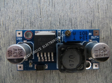
They're great and you can adjust the output by turning the potentiometer, but you'll need a multimeter to calibrate it. It's a cheap and easy power regulator solution, which is also very efficient (Thanx to @AWI)
-
haha tnx
Gues what.I just looked in the box of gadgets.
they are ... in the box still in plastic.Let's find out ;-) -
haha tnx
Gues what.I just looked in the box of gadgets.
they are ... in the box still in plastic.Let's find out ;-)@sincze Good luck. Let me hear of it works. Just be sure to power the buck converter externally and not from the Arduino.
Also on the back is an arrow which points from the Input through the output. But you're a smart guy, you've probably already figured that one out yourself.
-
@sincze Good luck. Let me hear of it works. Just be sure to power the buck converter externally and not from the Arduino.
Also on the back is an arrow which points from the Input through the output. But you're a smart guy, you've probably already figured that one out yourself.
-
@TheoL 12v attached, still no blue smoke. Let's bring it down to 3,3 for the antenna. Off-topic: Seems a bit of overkill to use this unit for just the antenna ??
@sincze I've got some buck converters that regulate 12V to 3.3V without any pain. I use it for my gesture controlled lamp. Works like a charm.
Well I'm by far any export on this field. But I'm working on a node which I couldn't get stable. The Node crashed after 6, 8 sometimes 12 hours. I've added a watchdog, which works great, but after the watchdog did it's work some sensors on the node just couldn't work. Although I've powered them externally.
To make this story shorter ;-). I found out that it's better to always power the radio externally. For some kind of reason it consumes more power than my ProMini 3.3V can provide. This symptom occurs when you add multiple sensors to an Arduino. It took me a long time to investigate what the problem was. But my conclusion is, just don't power anything from the Arduino and use an external power adapter if possible.
Except for dedicated Arduino's that can be found on openhardware. My sensebender has been running for 4 month on the same batteries without any problems.
Hello! It looks like you're interested in this conversation, but you don't have an account yet.
Getting fed up of having to scroll through the same posts each visit? When you register for an account, you'll always come back to exactly where you were before, and choose to be notified of new replies (either via email, or push notification). You'll also be able to save bookmarks and upvote posts to show your appreciation to other community members.
With your input, this post could be even better 💗
Register Login