From 1.5 to 2.0. Can't get it running
-
Yeah i saw this after i got in bed so i was about to try this in the morning.
But thank you for your answer.
Now i got my GW running but i got a new problem.If my node fail to deleiver a message for the last 6 tries i "gives up"
TSP:MSG:SEND 3-3-0-0 s=4,c=1,t=16,pt=2,l=2,sg=0,ft=0,st=ok:1
TSP:MSG:SEND 3-3-0-0 s=4,c=1,t=16,pt=2,l=2,sg=0,ft=0,st=ok:0
TSP:MSG:SEND 3-3-0-0 s=4,c=1,t=16,pt=2,l=2,sg=0,ft=0,st=ok:1
!TSP:MSG:SEND 3-3-0-0 s=4,c=1,t=16,pt=2,l=2,sg=0,ft=0,st=fail:0
!TSP:MSG:SEND 3-3-0-0 s=4,c=1,t=16,pt=2,l=2,sg=0,ft=1,st=fail:1
TSP:MSG:SEND 3-3-0-0 s=4,c=1,t=16,pt=2,l=2,sg=0,ft=2,st=ok:0
TSP:MSG:SEND 3-3-0-0 s=4,c=1,t=16,pt=2,l=2,sg=0,ft=0,st=ok:1
TSP:MSG:SEND 3-3-0-0 s=4,c=1,t=16,pt=2,l=2,sg=0,ft=0,st=ok:0
TSP:MSG:SEND 3-3-0-0 s=4,c=1,t=16,pt=2,l=2,sg=0,ft=0,st=ok:1
TSP:MSG:SEND 3-3-0-0 s=4,c=1,t=16,pt=2,l=2,sg=0,ft=0,st=ok:0
TSP:MSG:SEND 3-3-0-0 s=4,c=1,t=16,pt=2,l=2,sg=0,ft=0,st=ok:1
!TSP:MSG:SEND 3-3-0-0 s=4,c=1,t=16,pt=2,l=2,sg=0,ft=0,st=fail:0
!TSP:MSG:SEND 3-3-0-0 s=4,c=1,t=16,pt=2,l=2,sg=0,ft=1,st=fail:1
!TSP:MSG:SEND 3-3-0-0 s=4,c=1,t=16,pt=2,l=2,sg=0,ft=2,st=fail:0
!TSP:MSG:SEND 3-3-0-0 s=4,c=1,t=16,pt=2,l=2,sg=0,ft=3,st=fail:1
!TSP:MSG:SEND 3-3-0-0 s=4,c=1,t=16,pt=2,l=2,sg=0,ft=4,st=fail:0
!TSP:MSG:SEND 3-3-0-0 s=4,c=1,t=16,pt=2,l=2,sg=0,ft=5,st=fail:1
!TSM:UPL FAIL, SNP
TSM:FPAR
TSP:MSG:SEND 3-3-255-255 s=255,c=3,t=7,pt=0,l=0,sg=0,ft=0,st=bc:
!TSP:SEND:TNR
!TSP:SEND:TNR
!TSP:SEND:TNR
!TSP:SEND:TNR
!TSP:SEND:TNR
!TSP:SEND:TNR
!TSP:SEND:TNR
After this i can't get it to transmit any more and i have to push the resetbutton.
In this example i use a binary switch, pushing my button and when i hold my hand over the radio so the signal won't reach my GW this happends.
Any thoughts?
Thanks. -
Yeah i saw this after i got in bed so i was about to try this in the morning.
But thank you for your answer.
Now i got my GW running but i got a new problem.If my node fail to deleiver a message for the last 6 tries i "gives up"
TSP:MSG:SEND 3-3-0-0 s=4,c=1,t=16,pt=2,l=2,sg=0,ft=0,st=ok:1
TSP:MSG:SEND 3-3-0-0 s=4,c=1,t=16,pt=2,l=2,sg=0,ft=0,st=ok:0
TSP:MSG:SEND 3-3-0-0 s=4,c=1,t=16,pt=2,l=2,sg=0,ft=0,st=ok:1
!TSP:MSG:SEND 3-3-0-0 s=4,c=1,t=16,pt=2,l=2,sg=0,ft=0,st=fail:0
!TSP:MSG:SEND 3-3-0-0 s=4,c=1,t=16,pt=2,l=2,sg=0,ft=1,st=fail:1
TSP:MSG:SEND 3-3-0-0 s=4,c=1,t=16,pt=2,l=2,sg=0,ft=2,st=ok:0
TSP:MSG:SEND 3-3-0-0 s=4,c=1,t=16,pt=2,l=2,sg=0,ft=0,st=ok:1
TSP:MSG:SEND 3-3-0-0 s=4,c=1,t=16,pt=2,l=2,sg=0,ft=0,st=ok:0
TSP:MSG:SEND 3-3-0-0 s=4,c=1,t=16,pt=2,l=2,sg=0,ft=0,st=ok:1
TSP:MSG:SEND 3-3-0-0 s=4,c=1,t=16,pt=2,l=2,sg=0,ft=0,st=ok:0
TSP:MSG:SEND 3-3-0-0 s=4,c=1,t=16,pt=2,l=2,sg=0,ft=0,st=ok:1
!TSP:MSG:SEND 3-3-0-0 s=4,c=1,t=16,pt=2,l=2,sg=0,ft=0,st=fail:0
!TSP:MSG:SEND 3-3-0-0 s=4,c=1,t=16,pt=2,l=2,sg=0,ft=1,st=fail:1
!TSP:MSG:SEND 3-3-0-0 s=4,c=1,t=16,pt=2,l=2,sg=0,ft=2,st=fail:0
!TSP:MSG:SEND 3-3-0-0 s=4,c=1,t=16,pt=2,l=2,sg=0,ft=3,st=fail:1
!TSP:MSG:SEND 3-3-0-0 s=4,c=1,t=16,pt=2,l=2,sg=0,ft=4,st=fail:0
!TSP:MSG:SEND 3-3-0-0 s=4,c=1,t=16,pt=2,l=2,sg=0,ft=5,st=fail:1
!TSM:UPL FAIL, SNP
TSM:FPAR
TSP:MSG:SEND 3-3-255-255 s=255,c=3,t=7,pt=0,l=0,sg=0,ft=0,st=bc:
!TSP:SEND:TNR
!TSP:SEND:TNR
!TSP:SEND:TNR
!TSP:SEND:TNR
!TSP:SEND:TNR
!TSP:SEND:TNR
!TSP:SEND:TNR
After this i can't get it to transmit any more and i have to push the resetbutton.
In this example i use a binary switch, pushing my button and when i hold my hand over the radio so the signal won't reach my GW this happends.
Any thoughts?
Thanks.@xydix I suggest you try these changes:
- Increase TX power on both, GW and node, using
#define MY_RF24_PA_LEVEL RF24_PA_MAX- Increase distance between GW and node if they are too close (>5m)
- Add/substitute radio caps, ideally >100uF
- If none of that helps, please upload both sketches for further troubleshooting
-
Thank you guys for answers.
@tekka
What i want here is to know my sensors won't get in a state when i have to reset them.
I have one door sensor that is to far away and sometimes it won't reach the gateway. I will fix this later.
But still, i want to be sure my sensors reconnect to my GW.
If i for some reason have to disconnect my GW and open some doors, this will result in that i have to reset them later when my GW is up.
Thanks for reminding me to define PA level. Totally forgot about that. -
Thank you guys for answers.
@tekka
What i want here is to know my sensors won't get in a state when i have to reset them.
I have one door sensor that is to far away and sometimes it won't reach the gateway. I will fix this later.
But still, i want to be sure my sensors reconnect to my GW.
If i for some reason have to disconnect my GW and open some doors, this will result in that i have to reset them later when my GW is up.
Thanks for reminding me to define PA level. Totally forgot about that.@xydix said:
But still, i want to be sure my sensors reconnect to my GW.
As @sundberg84 pointed out, your node will try to reconnect after a timeout. Furthermore, you can prevent the node from searching a new parent after too many fails by setting a static parent (assumption: GW is the parent node):
#define MY_PARENT_NODE_ID 0 #define MY_PARENT_NODE_IS_STATIC -
I searched the forum and found a thread about this.
@tekka you posted this:replace
sleep(30000);with
if(isTransportOK()){
    sleep(30000);  // transport is OK, node can sleep
  }
  else {
    wait(5000); // transport is not operational, allow the transport layer to fix this
  }
And this will do it.
Now my node reconnect.
Is this the best way to do it?
I use battery powered sensors. Will this drain my batteries?
Will my node sleep as it should?
Haven't hade the time to measure this yet. -
I had it working like one day.
Now i have problems again. :-1:
Right now i am only using 2 nodes, batterypowered doorswitches.
I did a small change in one of my sketches, after that it didn't present itself to the GW/controller I guess.
I use Home Assistant as controller, and i deleted my "mysensors.json-file" to do a fresh start.
After this i can't get any node working.
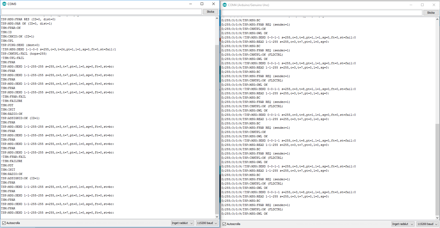
Side by side log from serial monitor:
@tekka GW recive messages, right? But node don't receive it?
@martinhjelmare
I hope you are the right person to ask because i use Home Assistant.
Can you please check my sketch.
Like i said, earlier it woked.
No error in HA log./** * The MySensors Arduino library handles the wireless radio link and protocol * between your home built sensors/actuators and HA controller of choice. * The sensors forms a self healing radio network with optional repeaters. Each * repeater and gateway builds a routing tables in EEPROM which keeps track of the * network topology allowing messages to be routed to nodes. * * Created by Henrik Ekblad <henrik.ekblad@mysensors.org> * Copyright (C) 2013-2015 Sensnology AB * Full contributor list: https://github.com/mysensors/Arduino/graphs/contributors * * Documentation: http://www.mysensors.org * Support Forum: http://forum.mysensors.org * * This program is free software; you can redistribute it and/or * modify it under the terms of the GNU General Public License * version 2 as published by the Free Software Foundation. * ******************************* * * DESCRIPTION * * Interrupt driven binary switch example with dual interrupts * Author: Patrick 'Anticimex' Fallberg * Connect one button or door/window reed switch between * digitial I/O pin 3 (BUTTON_PIN below) and GND and the other * one in similar fashion on digital I/O pin 2. * This example is designed to fit Arduino Nano/Pro Mini * */ // Enable debug prints to serial monitor #define MY_DEBUG // Enable and select radio type attached #define MY_RADIO_NRF24 //#define MY_RADIO_RFM69 #define MY_RF24_PA_LEVEL RF24_PA_MAX #include <SPI.h> #include <MySensors.h> #define SKETCH_NAME "Basementdoor" #define SKETCH_MAJOR_VER "1" #define SKETCH_MINOR_VER "0" int BATTERY_SENSE_PIN = A0; // select the input pin for the battery sense point int oldBatteryPcnt = 0; #define CHILD_ID 3 #define BUTTON_PIN 3 // Arduino Digital I/O pin for button/reed switch // Change to V_LIGHT if you use S_LIGHT in presentation below MyMessage msg(CHILD_ID, V_TRIPPED); void setup() { // use the 1.1 V internal reference #if defined(__AVR_ATmega2560__) analogReference(INTERNAL1V1); #else analogReference(INTERNAL); #endif // Setup the buttons pinMode(BUTTON_PIN, INPUT); // Activate internal pull-ups // digitalWrite(PRIMARY_BUTTON_PIN, HIGH); } void presentation() { // Send the sketch version information to the gateway and Controller sendSketchInfo(SKETCH_NAME, SKETCH_MAJOR_VER "." SKETCH_MINOR_VER); // Register binary input sensor to sensor_node (they will be created as child devices) // You can use S_DOOR, S_MOTION or S_LIGHT here depending on your usage. // If S_LIGHT is used, remember to update variable type you send in. See "msg" above. present(CHILD_ID, S_DOOR); } // Loop will iterate on changes on the BUTTON_PINs void loop() { uint8_t value; static uint8_t sentValue=2; // Short delay to allow buttons to properly settle sleep(5); value = digitalRead(BUTTON_PIN); if (value != sentValue) { // Value has changed from last transmission, send the updated value send(msg.set(value==HIGH ? 0 : 1)); sentValue = value; } // get the battery Voltage int sensorValue = analogRead(BATTERY_SENSE_PIN); #ifdef MY_DEBUG Serial.println(sensorValue); #endif // 1M, 470K divider across battery and using internal ADC ref of 1.1V // Sense point is bypassed with 0.1 uF cap to reduce noise at that point // ((1e6+470e3)/470e3)*1.1 = Vmax = 3.44 Volts // 3.44/1023 = Volts per bit = 0.003363075 int batteryPcnt = sensorValue / 10; #ifdef MY_DEBUG float batteryV = sensorValue * 0.003363075; Serial.print("Battery Voltage: "); Serial.print(batteryV); Serial.println(" V"); Serial.print("Battery percent: "); Serial.print(batteryPcnt); Serial.println(" %"); #endif if (oldBatteryPcnt != batteryPcnt) { // Power up radio after sleep sendBatteryLevel(batteryPcnt); oldBatteryPcnt = batteryPcnt; } // Sleep until something happens with the sensor if(isTransportOK()){ sleep(BUTTON_PIN-2, CHANGE, 0); // transport is OK, node can sleep } else { wait(5000); // transport is not operational, allow the transport layer to fix this } }I read this:
Send at least one initial value per V_TYPE. In version 2.0 of MySensors this has to be done in the loop function. See below for an example in 2.0 of how to make sure the initial value has been received by the controller.
But not sure if it is needed here and how to put that in my sketch. Please help a Newbe.
Edit:
BTW. I guess many had problem like this due to powering problems. When i measure, it's steady 3,36V on VCC and on my radio. -
Okay, i think i found a solution.
On my sensors i removed the onboard voltage regulator.
By coincidence i powered my sensor from only one AA battery when i was testing. I use battery booster and 2 AA otherwise.
Sudenly it worked. Presentation happend and sensor is working.
I measured again with a better multimeter. With one AA battery: 3,34V, with two AA batteries: 3,38V.
I tested several times and this is really the issue. I guess the pro mini or the radio is sensitive when it comes to higher voltage than 3.3V
After presentation i added the second battery without disconnecting and now it works.
This was never a problem with Mysensors 1.5.
Is the presentation more "sensitive" in 2.0?
Can anyone explain why this happend? Someone said that the NRF24-radio can handle up to 3,6V.
Anyone know how to "fix" a batterybooster?Please, if someone know. Tell me/us.
BUT! If you have problems with a sensor and use batterybooster/ removed onboard voltage regulator. Check voltage.
-
Okay, i think i found a solution.
On my sensors i removed the onboard voltage regulator.
By coincidence i powered my sensor from only one AA battery when i was testing. I use battery booster and 2 AA otherwise.
Sudenly it worked. Presentation happend and sensor is working.
I measured again with a better multimeter. With one AA battery: 3,34V, with two AA batteries: 3,38V.
I tested several times and this is really the issue. I guess the pro mini or the radio is sensitive when it comes to higher voltage than 3.3V
After presentation i added the second battery without disconnecting and now it works.
This was never a problem with Mysensors 1.5.
Is the presentation more "sensitive" in 2.0?
Can anyone explain why this happend? Someone said that the NRF24-radio can handle up to 3,6V.
Anyone know how to "fix" a batterybooster?Please, if someone know. Tell me/us.
BUT! If you have problems with a sensor and use batterybooster/ removed onboard voltage regulator. Check voltage.
Sketch looks OK. Sounds like a hardware issue. Have you tried replacing booster and/or radio?