RFM69HW temp-humidity node
-
I'm not sure why powering it from a pin is fundamentally different than powering it from the battery, unless the current max is exceeded, which it doesn't appear to be. Tis a mystery.
-
So, I removed the voltage regulator on the si7021 and shorted Vin to Vout on the pads where it used to be. The above anomaly persists.
I then re-ran the current consumption test that I did at earlier, again using the Dave Jones Microcurrent . This time it's showing just 57nA consumed with power to the si7021 breakout board and with no SDA or SCL datalines connected. So, virtually all of the previous current that was measured was being consumed by the voltage regulator, which isn't needed when everything is powered from just two AA batteries.
-
According to the si7021 datasheet, a typical standby current is 60nA, which is very close to what I measured on the si7021 breakout board in the post directly above.
60nA is not significant. Therefore, there is no need to switch the si7021 on and off using either a digital pin or a load switch. It can simply be on all the time, as it is in the current pcb board layout.
I changed the orientation of the sensor plug-in so that the sensor element will be facing up on the small board design. I also cleaned up some smaller details and sent the revised design to the fab last night.
-
@TimO
Thanks! That exactly matches what my micrometer says also, so I'll go with that.So now the question is: what diameter hole should I have drilled for that? Is there a rule of thumb? e.g. Would 1.45 be too snug? Too loose?
@NeverDie said:
So now the question is: what diameter hole should I have drilled for that? Is there a rule of thumb? e.g. Would 1.45 be too snug? Too loose?
Answering my own question, standard pin clearance on a thru-hole is apparently anywhere from 0.15mm to 0.8mm: http://electronics.stackexchange.com/questions/110959/how-much-clearance-should-you-include-in-through-hole-component-holes
So, I think I'll go for somewhere in the middle, say 0.25mm added to the pin diameter for the thru-hole diameter that's to be drilled.
A typical header pin is 0.65mm. So, the thru-hole diameter should be 0.65+0.25 = 0.9mm
From a routing perspective, smaller diameter pads are preferable, because they leave more room for routing traces. Pad diameter is going to be hole diameter plus some fixed incremental amount.
-
I changed the orientation of the sensor plug-in so that the sensor element will be facing up on the small board design. I also cleaned up some smaller details and sent the revised design to the fab last night.
@NeverDie said:
I changed the orientation of the sensor plug-in so that the sensor element will be facing up on the small board design. I also cleaned up some smaller details and sent the revised design to the fab last night.
As it turns out, there may be a good reason to have the sensor element face down after all: dust is less likely to settle on the cover/sensor-opening if it's facing down rather than up, simply due to gravity.
-
I assembled a node based on the interstitial design, but net net I don't see it as advantageous as compared to the other two, so I'll probably drop that approach. I've come up with a fourth design though and I've sent that to the fab, so presently three different designs are in queue for PCB fabrication.
-
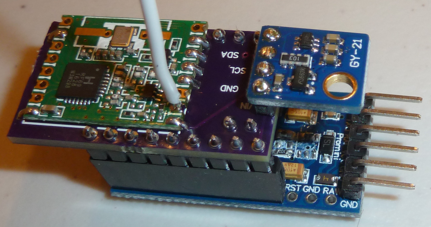
Here's a photo of a TH node based on a Pro Mini with an interstitial board:
-
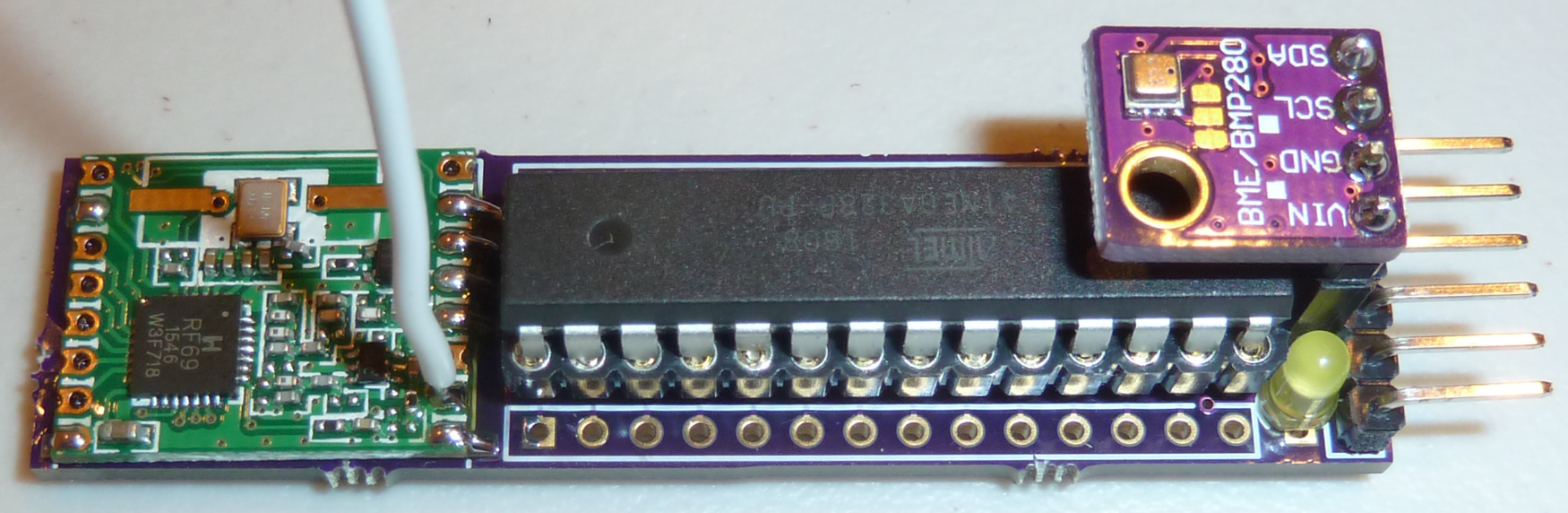
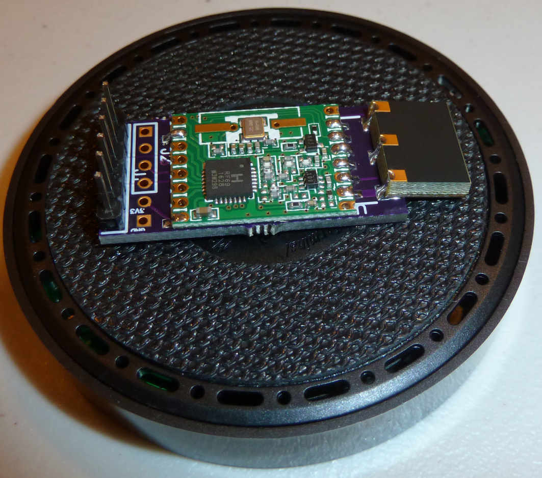
Here's the node from post #1 fully assembled, and with a BME280 instead of an si7021:
I'm starting to toy with the idea of having the radio also be a detachable module. The BME280 is the most expensive part on the board, and it's detachable. The atmega328p is detachable. If the radio were also detachable, it might speed up the assembly and test process. Also, if the radio were to go bad for some reason, one could just pop in a new one. Modularizing like that might make the whole thing easier to repair and troubleshoot, because you could always swap in "known good" modules to see if it fixes a particular problem. Anyhow, just an idea I'm kicking around. What do you all think? Make it more modular, or keep as is?
@NeverDie said:
I'm starting to toy with the idea of having the radio also be a detachable module. The BME280 is the most expensive part on the board, and it's detachable. The atmega328p is detachable. If the radio were also detachable, it might speed up the assembly and test process. Also, if the radio were to go bad for some reason, one could just pop in a new one. Modularizing like that might make the whole thing easier to repair and troubleshoot, because you could always swap in "known good" modules to see if it fixes a particular problem. Anyhow, just an idea I'm kicking around. What do you all think? Make it more modular, or keep as is?
I'm more and more liking the idea of detachable parts, especially as I continue to evolve the designs. That way if I move to a new PCB design, I can job pop the parts off the old PCB and pop them onto the new one without having to desolder things.
-
To keep things rolling I just sent in to be fabricated a test board with 1.45mm holes . It cost just 30 cents. If anyone has an idea for a better diameter to try, let me know and I'll send in one of those as well.

@NeverDie said:
To keep things rolling I just sent in to be fabricated a test board with 1.45mm holes . It cost just 30 cents. If anyone has an idea for a better diameter to try, let me know and I'll send in one of those as well.
Today I received the test board from the fab and tried it out:
As you can see from the photo (sorry that it's out of focus), it works in the sense that the female machine pin header now sits flush against the board. It's a snug fit though. For a female header that's longer and with more pins in it, I think the holes are going to need greater clearance or it will likely be too tight a fit. Just a wild guess, but I think 1.6mm diameter holes are what I should try next, and with a 14 pin female machine pin header.
-
@NeverDie said:
Here's a photo of a TH node based on a Pro Mini with an interstitial board:
Where can I order this board?
Do you have a location where one could see all the boards you have developed? -
I'd say that so far this is the easiest one to assemble while still being moderately compact:
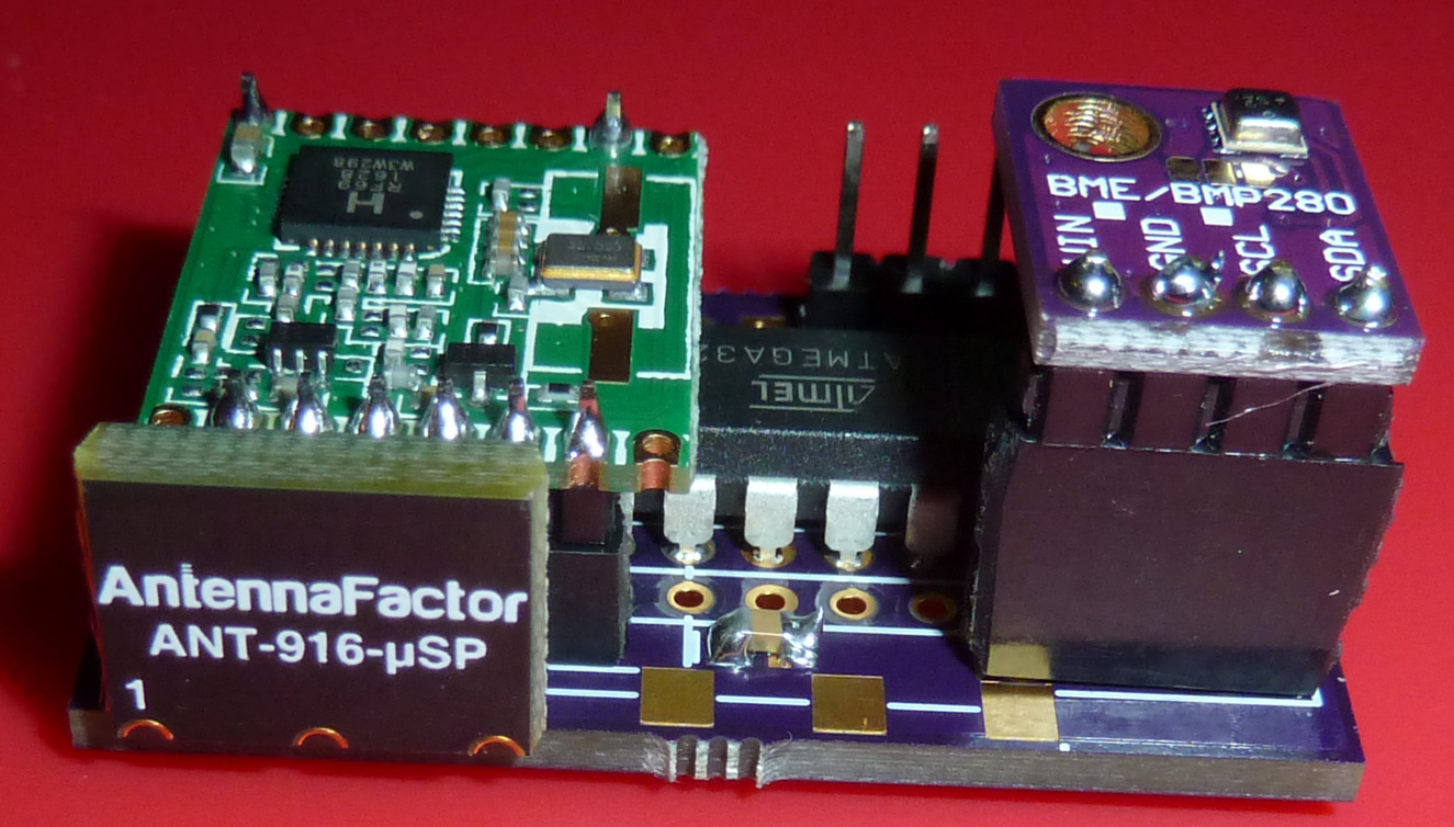
It's also a bit more modular in the sense that the radio and the TH sensor can be plugged in or easily removed. Also nice is that all the atmega328p pins are exposed for easy access.This one is smaller and more specialized:
I'm improving both of them though to use machine pins on the TH sensor to reduce the overall height. I've already sent the machine pin smaller version to the fab.
-
@NeverDie said:
Here's a photo of a TH node based on a Pro Mini with an interstitial board:
Where can I order this board?
Do you have a location where one could see all the boards you have developed?@korttoma said:
@NeverDie said:
Here's a photo of a TH node based on a Pro Mini with an interstitial board:
Where can I order this board?
Do you have a location where one could see all the boards you have developed?On the other hand, if you really do want it, I could post it. I'm willing to accommodate Hero members much more than those who are all take and no give.
-
I'm removing the voltage regulator from the BME280, because even though it appears to work fine with it installed even when fed a voltage of 3.3v, at some point it's going to be in the way if being run from even lower voltages. After removing the voltage regulator, I bridge across it using a bit of solid core copper wire and some solder, thusly:
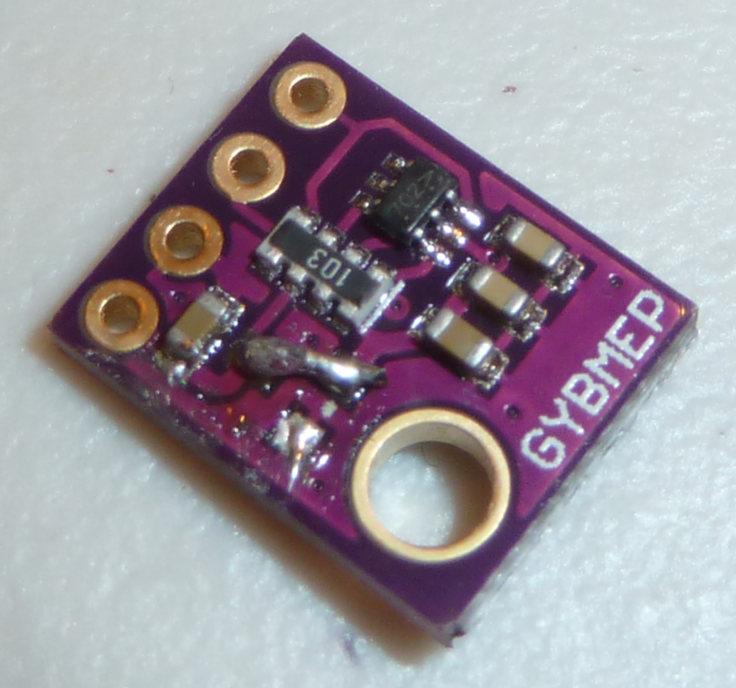
I'm not applying any flux, because I don't want to contaminant the BME280 sensor, either from the flux or from a flux remover afterward. -
With the BME280 voltage regulator removed, I powered it stand-alone using a 3.3V bench power supply. Using Dave Jones's uCurrent in conjunction with a Fluke 87V multimeter, I measure the standby current at a mere 155 nanoamps. I had planned to power it from pins on the atmega328p and then powering it down between measurements, but at 155na I'm not sure it even matters, provided it's being powered from a battery. :smile: On the other hand, if the entire mote is being powered from a capacitor that's charged from solar energy that's harvested from only weak ambient indoor light.... I guess in that scenario it might depend on the relative leakage rate of the capacitor that's used for the mote's energy storage as to whether or not it's worth fussing about.
Hello! It looks like you're interested in this conversation, but you don't have an account yet.
Getting fed up of having to scroll through the same posts each visit? When you register for an account, you'll always come back to exactly where you were before, and choose to be notified of new replies (either via email, or push notification). You'll also be able to save bookmarks and upvote posts to show your appreciation to other community members.
With your input, this post could be even better 💗
Register Login