Water Leak Detection
-
We just had a water heater fail so I'm in the middle of exactly the same project. I'm waiting on aliexpress orders for all my sensors but I'm planning on starting with multiple leak detectors in each bathroom (under sinks and toilets), the laundry room, the kitchen, and the water heater. I looked at all of those sensors and didn't like any of them. Right now, I'm going to try these: www.ebay.com/itm/231594180289
which have 2 contacts spaced a little bit apart. They seem to work fine so far but I haven't tried hooking them to an arduino yet. I'm hoping I can find them for cheaper before I place my final order (I need about 12 of them).For stage 2 of my plan, I'm going to install actuated valves that will turn off the water when a leak is detected. Valves are about $30 and work on 5V from this store (click their store link for lots of options): http://www.aliexpress.com/store/product/2-Way-1-2-Brass-Motor-Valve-with-manual-override-DN15-DC5V-5-wires/414681_1695915390.html
I'm also going to use a H-bridge module to allow reversing the valve w/ 2 pins: http://www.aliexpress.com/item/5pcs-lot-H-bridge-Stepper-Motor-Dual-DC-Motor-Driver-Controller-Board-For-Arduino-HG7881/1927732289.html -
FYI - after some more research (while waiting for the slow boat from China to arrive with my parts), I think there are some better options for the valve control. Several pages report that it's easy to burn out the HG7881 chips but that the EasyDriver module is much more robust. The EasyDriver says it needs 6V but I've seen several people report that it works fine (depending on the motor) down to 3.5V and can be had for not much more than the HG7881 so that seems like a better choice. It is designed fpr a stepper motor driver and the valves are simple 2 wire motors but I think it will still work fine - I'll give it a try and see when the parts arrive.
For the valve, brass fixtures have lead in them (as a hardening agent) and even supposed lead free brass has been found to increase the lead content in building water supplies so I'm going to only use the stainless steel models. They're only a few dollars more and start at 1/2" and go up so they won't work for some applications but I think they are a safer choice (especially given what I'm guessing is dubious quality control on lead in China). I'm going to order one of each and test them out.
http://www.aliexpress.com/item/EasyDriver-Stepper-Motor-Driver-V44-A3967-Free-Shipping/1569795645.html
http://www.aliexpress.com/store/product/1-2-SS304-electric-valve-2-port-DN15-motorized-valve-5-wires-DC5V-electric-motor-valve/414681_1865670445.html -
One more update: The leak sensors I posted above are junk. I ordered 2 of them to test with and both are failures. Only one of the wires is connected to the sensor pad and the connections are terminated under a giant blob of epoxy so there is easy way to fix them. I think that form factor is perfect but I can't recommend ordering from that link (I'm waiting to hear back from the seller to see what they want to do).
-
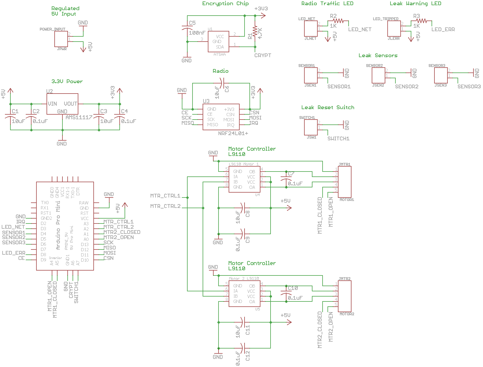
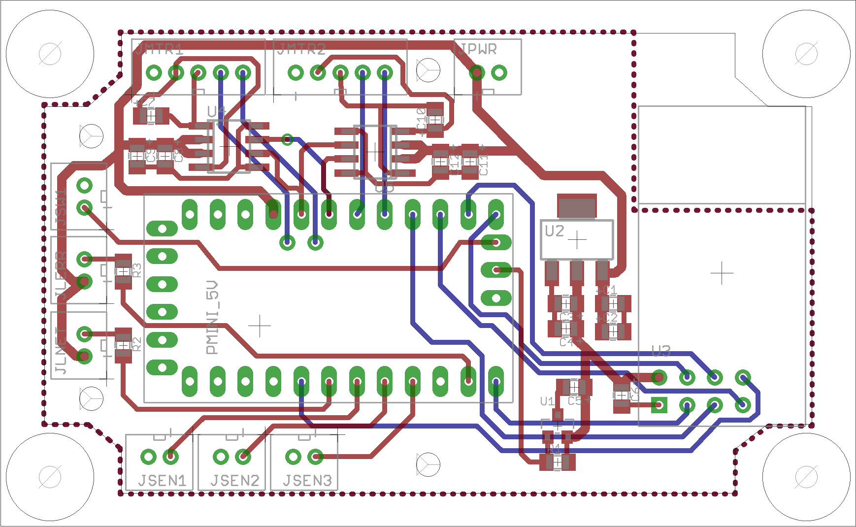
More updates: The water sensors I posted before work fine. I didn't realize that they aren't a simple contact switch - there is some circuitry inside them so they are directional and do require 5V. I also received a valve today so I have everything I need to build a prototype. Since I need 8 of these for my house (3 bathrooms, laundry, water heater, kitchen), I decided to make a custom PCB so I've been learning how to do that this week. I bought a sample box to use which had dimensional drawings so I could size a PCB board to fit. I'm going to try and make a single board for all my cases which will allow 2 valves to be controlled and have 3 water sensors.
Here's a couple of pics of my current schematic and board layout. The J boxes are JST style female connectors and motor controller is taken from the HG7881 module documentation. I've also created a small Eagle PCB library for all the components including the ProMini clone pad layout which is a bit different than the standard ones. I'm not going to try and fab them until I get the box in and can check my dimensions. Once I have a working breadboard setup for this, I'll start a new thread to get any feedback on the design.
-
Great projects... i made a slightly easier version i found on youtube
Took an old fire-alarm och connected two wires, one to + and one to the test function button. Shorting these two wires rendered the alarm (test function) was triggered. Then i put two screws with a cm aside and connected the two wires to the screwes. If water appears it will connect the two wires and alarm is triggered... as a bonus i have a fire-alarm as well.
This project isnt MySensored though... but i guess that could be done as well.
Controller: Proxmox VM - Home Assistant
MySensors GW: Arduino Uno - W5100 Ethernet, Gw Shield Nrf24l01+ 2,4Ghz
MySensors GW: Arduino Uno - Gw Shield RFM69, 433mhz
RFLink GW - Arduino Mega + RFLink Shield, 433mhz -
Great projects... i made a slightly easier version i found on youtube
Took an old fire-alarm och connected two wires, one to + and one to the test function button. Shorting these two wires rendered the alarm (test function) was triggered. Then i put two screws with a cm aside and connected the two wires to the screwes. If water appears it will connect the two wires and alarm is triggered... as a bonus i have a fire-alarm as well.
This project isnt MySensored though... but i guess that could be done as well.
@sundberg84 I approached it from the other direction, i.e., I took the SoilMoistSensor sketch and added a buzzer function to it. The basic sketch sleeps when no water is present and an interrupt that is triggered if water is detected. I used the water level sensor but could have just as well used two bare wires close together like you did (probably would be better and certainly cheaper if I did--the water level sensor was overkill for this purpose).
-
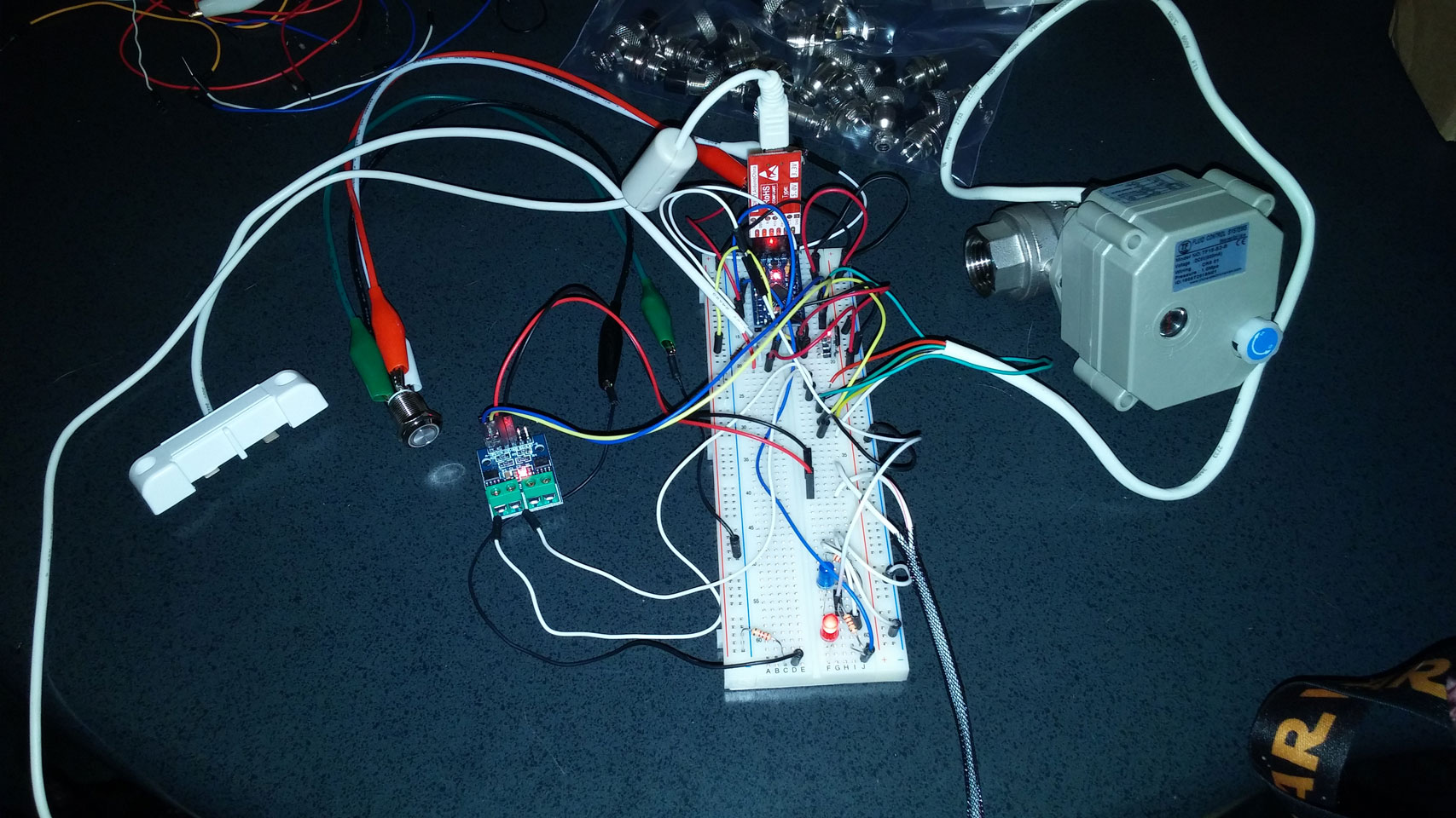
It's ALIVE!!! Ok - not really, but I've finished my first milestone. I've wired up a bread board prototype with several status LED's, a leak sensor, an override switch (for clearing a "leak"), the motor controller, and motorized valve. I'm very impressed with the valve so far - it works on 5V, doesn't use much current (~50mA), it cuts power and soon as the limit is hit, and the status sensors are a great feature. Since the valve is working so well, I've ordered more and need to try this with powering 2 valves at one time from 1 set of Arduino pins (no reason to think this won't work since they're just tripping a relay) which I need for my washing machine leak sensor.
I've finished V1 of the sketch code including LED, Switch, and Valve classes which handle all the state changes. The valve code includes time outs for how long power should be applied as well as a duty cycle to not overheat the H-bridge (it doesn't seem to get hot at all so far). The valve also reports state changes (closed, closing, opened, opening) so the LED's be set to can light or blink accordingly.
I haven't tied the code into MySensors yet but that's a trivial addition now that the core logic is working. I have some RFM69W radios arriving tomorrow so that will be the next addition.
Here's my bread board - not because it's particularly interesting, but just because I'm excited that the firmware is working so well and want to share :smiley:.
-
Here's another great leak "sensor": rope leak detector. The nice part about this is that it can cover a large area and it's basically white so it looks nice. I'm planning on cutting the 8 foot length up in to 15-20cm lengths to use in multiple locations.
There are four wires in the sensor in the rope, 2 black, 1 white, 1 red. The only ones that matter are the black ones. Feed 5V to one of the black wires and attach the other to an analog pin. When dry, the pin reads about 20-30 (out of 0-1023 analog range). When wet, it will read anywhere from 60-150. That's not high enough to trip the digital HIGH value using digitalRead() so it needs to be hooked up to an analog pin to work properly.
-
It's ALIVE!!! Ok - not really, but I've finished my first milestone. I've wired up a bread board prototype with several status LED's, a leak sensor, an override switch (for clearing a "leak"), the motor controller, and motorized valve. I'm very impressed with the valve so far - it works on 5V, doesn't use much current (~50mA), it cuts power and soon as the limit is hit, and the status sensors are a great feature. Since the valve is working so well, I've ordered more and need to try this with powering 2 valves at one time from 1 set of Arduino pins (no reason to think this won't work since they're just tripping a relay) which I need for my washing machine leak sensor.
I've finished V1 of the sketch code including LED, Switch, and Valve classes which handle all the state changes. The valve code includes time outs for how long power should be applied as well as a duty cycle to not overheat the H-bridge (it doesn't seem to get hot at all so far). The valve also reports state changes (closed, closing, opened, opening) so the LED's be set to can light or blink accordingly.
I haven't tied the code into MySensors yet but that's a trivial addition now that the core logic is working. I have some RFM69W radios arriving tomorrow so that will be the next addition.
Here's my bread board - not because it's particularly interesting, but just because I'm excited that the firmware is working so well and want to share :smiley:.
@TD22057
Hi, I've sourced same water detector and electronic value.
I can't seem to work out how the water sensor functions - i notice you wired it to 5V on red and black to D4, but is there a trick in terms of how it works ?I assume you are reading the D4 pin in your code ? Could you pls help out/share your code ?
How you finding the reliability of the sensor and value ?kinds regards
mars000 -
@TD22057
Hi, I've sourced same water detector and electronic value.
I can't seem to work out how the water sensor functions - i notice you wired it to 5V on red and black to D4, but is there a trick in terms of how it works ?I assume you are reading the D4 pin in your code ? Could you pls help out/share your code ?
How you finding the reliability of the sensor and value ?kinds regards
mars000@mars000 said in Water Leak Detection:
@TD22057
I can't seem to work out how the water sensor functions - i notice you wired it to 5V on red and black to D4, but is there a trick in terms of how it works ?
I assume you are reading the D4 pin in your code ? Could you pls help out/share your code ?
How you finding the reliability of the sensor and value ?Honestly - I don't remember. Re-reading the thread, I believe they worked fine but that 5V was required. Try hooking them up to an analog pin and reading the value there. They might be not be passing enough voltage to trigger a digital reading. I actually never deployed the design above - I switched to a more modular design and used the rope sensors shown above. I haven't had any problems with the valves - of course they don't cycle at all since I don't have any leaks, but they work when I test them.
-
@mars000 said in Water Leak Detection:
@TD22057
I can't seem to work out how the water sensor functions - i notice you wired it to 5V on red and black to D4, but is there a trick in terms of how it works ?
I assume you are reading the D4 pin in your code ? Could you pls help out/share your code ?
How you finding the reliability of the sensor and value ?Honestly - I don't remember. Re-reading the thread, I believe they worked fine but that 5V was required. Try hooking them up to an analog pin and reading the value there. They might be not be passing enough voltage to trigger a digital reading. I actually never deployed the design above - I switched to a more modular design and used the rope sensors shown above. I haven't had any problems with the valves - of course they don't cycle at all since I don't have any leaks, but they work when I test them.
-
Great job @TD22057
Could you share your sketch???
I´m working in something similar, but without the water sensor.
The valve is similar as well, buy it has 3 way, but still with 5 wires.Do you remender, or could check, how did you configured the valve sensor? Debouncering or not?
I want select water from two different places, so the 3 way...
My project has a button to local valve operation, two leds to indicate from where water is comming, H-bridge to control the valve motor, and I use Home Assistant receiving and controlling valve status, and receiving the signal from valve´s status sensor.
Here is my code:
#define MY_DEBUG #define MY_RADIO_NRF24 #define MY_REPEATER_FEATURE #define MY_NODE_ID 10 #include <SPI.h> #include <MySensors.h> #include <DHT.h> // #include <Bounce2.h> // PINAGEM #define int1 6 // ATUADOR PRA H BRIDGE #define int2 7 // ATUADOR PRA H BRIDGE #define button 4 // BOTAO LOCAL PARA MUDANÇA #define info_rua 11 // SENSOR RETORNO DA VALVULA QUANDO RUA SELECIONADO #define info_cist 12 // SENSOR RETORNO DA VALVULA QUANDO CISTERNA SELECIONADO #define led_rua 9 // LED ACENDE PRA ÁGUA DA RUA #define led_cist 10 // LED ACENDE PRA ÁGUA DA CISTERNA #define CHILD_ID_ACT 0 #define CHILD_ID_ESTADO 1 // MOTOR boolean buttonState = LOW; int rotDirection = 0; // 0 PRA CISTERNA E 1 PRA RUA int pressed = false; bool initialValueSent = false; bool state; //sensores de fim de curso int valor_rua = 0; int valor_cist = 0; MyMessage msgSwitch(CHILD_ID_ACT, V_STATUS); // SWITCH PARA MUDAR O ESTADO MyMessage msgState(CHILD_ID_ESTADO, V_TRIPPED); //SENSOR DO ESTADO void presentation() { sendSketchInfo("Seletor Agua", "1.0"); wait(200); present(CHILD_ID_ACT, S_SPRINKLER); wait(200); present(CHILD_ID_ESTADO, S_SPRINKLER); } void setup() { pinMode(int1, INPUT); pinMode(int2, INPUT); pinMode(button, INPUT); pinMode(info_rua, INPUT); pinMode(info_cist, INPUT); pinMode(led_rua, OUTPUT); pinMode(led_cist, OUTPUT); //definir estado inicial da valvula digitalWrite(int1, LOW); digitalWrite(int2, HIGH); digitalWrite(led_rua, LOW); digitalWrite(led_cist, HIGH); send(msgSwitch.set(0)); // setup do botao e dos sensores de fim de curso digitalWrite(button, HIGH); digitalWrite(info_rua, HIGH); digitalWrite(info_cist, HIGH); } void loop() { valor_rua = digitalRead(info_rua); valor_cist = digitalRead(info_cist); // valores iniciais if (!initialValueSent) { Serial.println("Sending initial value"); send(msgSwitch.set(0)); send(msgState.set(0)); Serial.println("Requesting initial value from controller"); request(CHILD_ID_ACT, V_STATUS); wait(2000, C_SET, V_STATUS); } // ler estado do botão if (digitalRead(button) == true) { pressed = !pressed; } while (digitalRead(button) == true); wait(20); // se botao pressionado if (pressed == true & rotDirection == 0) { digitalWrite(int1, HIGH); digitalWrite(int2, LOW); digitalWrite(led_cist, LOW); rotDirection = 1; send(msgSwitch.set(1)); wait(20); } if (pressed == true & rotDirection == 1) { digitalWrite(int1, LOW); digitalWrite(int2, HIGH); digitalWrite(led_rua, LOW); digitalWrite(led_cist, HIGH); rotDirection = 0; send(msgSwitch.set(0)); wait(20); } if (valor_rua == 1) { digitalWrite(led_rua, HIGH); } if (valor_rua == 0) { digitalWrite(led_rua, LOW); } if (valor_cist == 1) { digitalWrite(led_cist, HIGH); } if (valor_cist == 0) { digitalWrite(led_cist, LOW); } } void receive(const MyMessage &message) { if (message.isAck()) { Serial.println("This is an ack from gateway"); } if (message.type == V_STATUS) { if (!initialValueSent) { Serial.println("Receiving initial value from controller"); initialValueSent = true; } state = message.getBool(); if (state == 0) { digitalWrite(int1, LOW); digitalWrite(int2, HIGH); digitalWrite(led_rua, LOW); digitalWrite(led_cist, HIGH); rotDirection = 0; send(msgSwitch.set(0)); } if (state == 1) { digitalWrite(int1, HIGH); digitalWrite(int2, LOW); digitalWrite(led_rua, HIGH); digitalWrite(led_cist, LOW); rotDirection = 1; send(msgSwitch.set(1)); } } } -
Look here under Valve: https://github.com/TD22057/TD-Arduino-Core
-
Look here under Valve: https://github.com/TD22057/TD-Arduino-Core
Great work, and thanks for the quick answer!
I will try using it...I noticed you have coded a sonar sensor library as well.
I have another projeto for auto flushing an urinal, and got this sensor:
https://www.aliexpress.com/item/32332773388.html?spm=a2g0s.9042311.0.0.3b60b90avbfLZ9Could it work with your library?
Thanks again!!!
-
Here's another great leak "sensor": rope leak detector. The nice part about this is that it can cover a large area and it's basically white so it looks nice. I'm planning on cutting the 8 foot length up in to 15-20cm lengths to use in multiple locations.
There are four wires in the sensor in the rope, 2 black, 1 white, 1 red. The only ones that matter are the black ones. Feed 5V to one of the black wires and attach the other to an analog pin. When dry, the pin reads about 20-30 (out of 0-1023 analog range). When wet, it will read anywhere from 60-150. That's not high enough to trip the digital HIGH value using digitalRead() so it needs to be hooked up to an analog pin to work properly.
@TD22057 said in Water Leak Detection:
Here's another great leak "sensor": rope leak detector. The nice part about this is that it can cover a large area and it's basically white so it looks nice. I'm planning on cutting the 8 foot length up in to 15-20cm lengths to use in multiple locations.
There are four wires in the sensor in the rope, 2 black, 1 white, 1 red. The only ones that matter are the black ones. Feed 5V to one of the black wires and attach the other to an analog pin. When dry, the pin reads about 20-30 (out of 0-1023 analog range). When wet, it will read anywhere from 60-150. That's not high enough to trip the digital HIGH value using digitalRead() so it needs to be hooked up to an analog pin to work properly.
I've read horror stories where veritable running rivers of water are flooding a house but don't happen to run through the point location where a small leak detector was placed. This rope sounds like a good way to cast a wider net so as to better avoid having an undetected disaster like that.
Does anyone here know how it works? Does it sense water by capacitance, conduction, or some other way?
-
@TD22057 said in Water Leak Detection:
Here's another great leak "sensor": rope leak detector. The nice part about this is that it can cover a large area and it's basically white so it looks nice. I'm planning on cutting the 8 foot length up in to 15-20cm lengths to use in multiple locations.
There are four wires in the sensor in the rope, 2 black, 1 white, 1 red. The only ones that matter are the black ones. Feed 5V to one of the black wires and attach the other to an analog pin. When dry, the pin reads about 20-30 (out of 0-1023 analog range). When wet, it will read anywhere from 60-150. That's not high enough to trip the digital HIGH value using digitalRead() so it needs to be hooked up to an analog pin to work properly.
I've read horror stories where veritable running rivers of water are flooding a house but don't happen to run through the point location where a small leak detector was placed. This rope sounds like a good way to cast a wider net so as to better avoid having an undetected disaster like that.
Does anyone here know how it works? Does it sense water by capacitance, conduction, or some other way?
@chrismyers81 and @TD22057, from arduino forum, found a way to use it. Check here:
https://forum.arduino.cc/index.php?topic=256231.msg2494469#msg2494469But this rope will certainly disagree with my wife's idea of beautiful decor! :sweat_smile:
Despite all the work on finding the best place to place the sensor, accidents can occur, of course, but have those people worked on finding that place properly?
I think the best way avoiding those disasters is reading the main water flow and create automations based on volume of water, linked with others events, just like garden irrigation, people in the bathrooms, pool filling, car wash, time of day and, of course, flood sensors at strategic points. This is the way I will do!
The problem is how to measur water flow without adding chinese components in contact with your water!
-
@chrismyers81 and @TD22057, from arduino forum, found a way to use it. Check here:
https://forum.arduino.cc/index.php?topic=256231.msg2494469#msg2494469But this rope will certainly disagree with my wife's idea of beautiful decor! :sweat_smile:
Despite all the work on finding the best place to place the sensor, accidents can occur, of course, but have those people worked on finding that place properly?
I think the best way avoiding those disasters is reading the main water flow and create automations based on volume of water, linked with others events, just like garden irrigation, people in the bathrooms, pool filling, car wash, time of day and, of course, flood sensors at strategic points. This is the way I will do!
The problem is how to measur water flow without adding chinese components in contact with your water!
@OliverDog said in Water Leak Detection:
The problem is how to measur water flow without adding chinese components in contact with your water!
@OliverDog Supposedly Moen's Flo can measure leaks down to even 1 drop a minute, which is pretty amazing. Allegedly its software already has some amount of leak detection built in based on usage patterns. Is it worth it? Compared to most flow meters, which can't resolve to a drop a minute, it's quite expensive. However, I look at it the same as insurance, except better, and compared to the cost of insurance it's... cheap? I would hope that the price premium buys better quality than chinesium, but.... who knows? I'm concerned it might reduce dynamic water pressure, and none of the reviews think to check for that. It's a 3/4" connection rather than 1 inch, so it's going to have some effect. And it's yet another thing that might break or go bad with time. I like the idea of it, but for me it's in the category of "nice to have" rather than "gotta have.".
-
@OliverDog said in Water Leak Detection:
The problem is how to measur water flow without adding chinese components in contact with your water!
@OliverDog Supposedly Moen's Flo can measure leaks down to even 1 drop a minute, which is pretty amazing. Allegedly its software already has some amount of leak detection built in based on usage patterns. Is it worth it? Compared to most flow meters, which can't resolve to a drop a minute, it's quite expensive. However, I look at it the same as insurance, except better, and compared to the cost of insurance it's... cheap? I would hope that the price premium buys better quality than chinesium, but.... who knows? I'm concerned it might reduce dynamic water pressure, and none of the reviews think to check for that. It's a 3/4" connection rather than 1 inch, so it's going to have some effect. And it's yet another thing that might break or go bad with time. I like the idea of it, but for me it's in the category of "nice to have" rather than "gotta have.".
@NeverDie There's a danger of trying to find a overall solution for distinctly different scenarios even if they all concern water escape.
Leakage or loss within a domestic supply can be readily picked up by a Class D water meter with K-1. My domestic meter is Class D with a 1 Litre sensor linked to Domoticz so any leakage shows up overnight. Your a drip per minute sounds miniscule, but if you sleep the average 8 hours, that's 480 drips overnight, chances are it will trigger the meter.
The beauty of modern positive displacement meters is they are mounting agnostic, have remarkably low pressure drop and are built for 20+ years reliable life. Usually the sensor costs more than the meter, but even $150 is cheaper than the insurance loss if something goes wrong.For leakage in a say a bathroom, wet socks are the surest indicator there is a problem to investigate. Almost built one to alarm for a water softener drain overflowing, but ended up altering the plumbing with a backup overflow. Problem solved but a sensor node remains on my to-do list.
A burst will cause damage within minutes and chances are it will occur when you are not there or within earshot. Only had one instance where a valve literally burst (faulty casting?) but heard it and managed to isolate quickly. Had I been elsewhere and received an alarm because a sensor detected it, by the time I responded the damage would have been horrendous (3m3 tank and pumped supply :face_with_rolling_eyes: ), but a public water supply will continue to feed regardless.
For the vast majority of normal sensors they rely on detecting water on the floor to alert you to a partial but unusual leak from a stuck ballcock, stuck/split air valve or a loosened drain connection, the only question is the detection area.
However, returning to that Class D, it is equally possible that the system alarms for unusual triggers when nobody is in the house (say intruder alarm active) or at night times when asleep, one litre of water is a lot easier to deal with. It is equally possible to trigger an electronic shut-off valve if the flow exceeds normal use as with a burst.
Just my 2c... -
@NeverDie There's a danger of trying to find a overall solution for distinctly different scenarios even if they all concern water escape.
Leakage or loss within a domestic supply can be readily picked up by a Class D water meter with K-1. My domestic meter is Class D with a 1 Litre sensor linked to Domoticz so any leakage shows up overnight. Your a drip per minute sounds miniscule, but if you sleep the average 8 hours, that's 480 drips overnight, chances are it will trigger the meter.
The beauty of modern positive displacement meters is they are mounting agnostic, have remarkably low pressure drop and are built for 20+ years reliable life. Usually the sensor costs more than the meter, but even $150 is cheaper than the insurance loss if something goes wrong.For leakage in a say a bathroom, wet socks are the surest indicator there is a problem to investigate. Almost built one to alarm for a water softener drain overflowing, but ended up altering the plumbing with a backup overflow. Problem solved but a sensor node remains on my to-do list.
A burst will cause damage within minutes and chances are it will occur when you are not there or within earshot. Only had one instance where a valve literally burst (faulty casting?) but heard it and managed to isolate quickly. Had I been elsewhere and received an alarm because a sensor detected it, by the time I responded the damage would have been horrendous (3m3 tank and pumped supply :face_with_rolling_eyes: ), but a public water supply will continue to feed regardless.
For the vast majority of normal sensors they rely on detecting water on the floor to alert you to a partial but unusual leak from a stuck ballcock, stuck/split air valve or a loosened drain connection, the only question is the detection area.
However, returning to that Class D, it is equally possible that the system alarms for unusual triggers when nobody is in the house (say intruder alarm active) or at night times when asleep, one litre of water is a lot easier to deal with. It is equally possible to trigger an electronic shut-off valve if the flow exceeds normal use as with a burst.
Just my 2c...@zboblamont I knew a guy on one of the other home automation forums who had his water supply turn off automatically every time he leaves home. That seems a bit limiting to me (you can't run the dishwasher or laundry or even your ice maker when you're gone), but maybe it's wise.
Which Class D meter do you recommend?
Hello! It looks like you're interested in this conversation, but you don't have an account yet.
Getting fed up of having to scroll through the same posts each visit? When you register for an account, you'll always come back to exactly where you were before, and choose to be notified of new replies (either via email, or push notification). You'll also be able to save bookmarks and upvote posts to show your appreciation to other community members.
With your input, this post could be even better 💗
Register Login