'MySensoring' a Kidde Smoke Detector. (Completed)
-
Where does one find these files you speak of? :-)
@ServiceXp
each device has xml and json files...
you can look at Rex's example
you can create and upload them to your vera.

-
@ServiceXp
each device has xml and json files...
you can look at Rex's example
you can create and upload them to your vera.
@BulldogLowell Thank you Sir, I will chew on this for a bit.
-
Is there a max sleep time allowed? What am I doing wrong...? it's not sleeping for 9 hours.. Not even close. And I've confirmed it's not waking on interrupt.
unsigned long SLEEP_TIME = 32400; sensor_node.sleep(SIREN_SENSE_PIN-2,FALLING, SLEEP_TIME * 1000); -
Is there a max sleep time allowed? What am I doing wrong...? it's not sleeping for 9 hours.. Not even close. And I've confirmed it's not waking on interrupt.
unsigned long SLEEP_TIME = 32400; sensor_node.sleep(SIREN_SENSE_PIN-2,FALLING, SLEEP_TIME * 1000);@ServiceXp
you are overflowing your int!
32400 is an int
1000 is an int
multiply them together and well, there you have it...Try:
sensor_node.sleep(SIREN_SENSE_PIN-2,FALLING, SLEEP_TIME * 1000UL); -
@ServiceXp
you are overflowing your int!
32400 is an int
1000 is an int
multiply them together and well, there you have it...Try:
sensor_node.sleep(SIREN_SENSE_PIN-2,FALLING, SLEEP_TIME * 1000UL);@BulldogLowell Thanks, Can you point me to an explanation to what the UL does? Coding for me is like herding cats, I can't ever seem to get it right.. :-)
-
@BulldogLowell Thanks, Can you point me to an explanation to what the UL does? Coding for me is like herding cats, I can't ever seem to get it right.. :-)
@ServiceXp
sure,
here in arduino land an int is 16 bits, and default is signed
so for 16 bit ints, the maximum representable value 2^(16 − 1) =32,768 (signed)
adding the UL tells the compiler "Hey dude, I'm an Unsigned Long!"
UL's are 32bit... and for 32 bits, well the the maximum representable value 2^32 = 4,294,967,295
-
@ServiceXp
sure,
here in arduino land an int is 16 bits, and default is signed
so for 16 bit ints, the maximum representable value 2^(16 − 1) =32,768 (signed)
adding the UL tells the compiler "Hey dude, I'm an Unsigned Long!"
UL's are 32bit... and for 32 bits, well the the maximum representable value 2^32 = 4,294,967,295
@BulldogLowell ah, very cool, Thanks for the explanation.
-
I think it's complete.
Hardware wise this project is VERY easy to complete. The hardest part was arranging the hardware to fit in the case. The sketch on the other hand was a pain in my butt and I'm sure it's VERY inefficient, but does seem to work without ANY false alarms.
Thanks to @BulldogLowell for the help!
Mod Goals:
- Detect when the siren is powered up and transmit that "trip" to Vera (for various processes)
- Use interrupt to start Arduino with a 9 hour "heart beat".
- Utilize the detectors battery power.
Because this detector has on-board battery level checks and warnings, I don't have to mess around with building a battery circuit.
BOM:
- Pro Mini
- I'm using Optocoupler for the speaker power isolation (you could probably just sense the 3.3v speaker voltage directly).
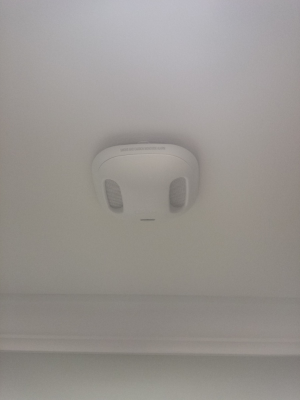
- Kidde Detector Used (any can be used providing you have the space inside)
Here is the sketch:
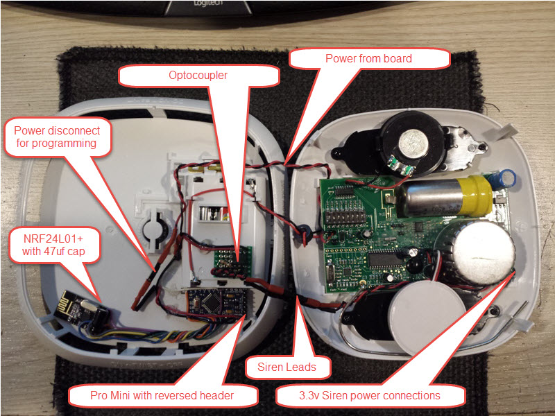
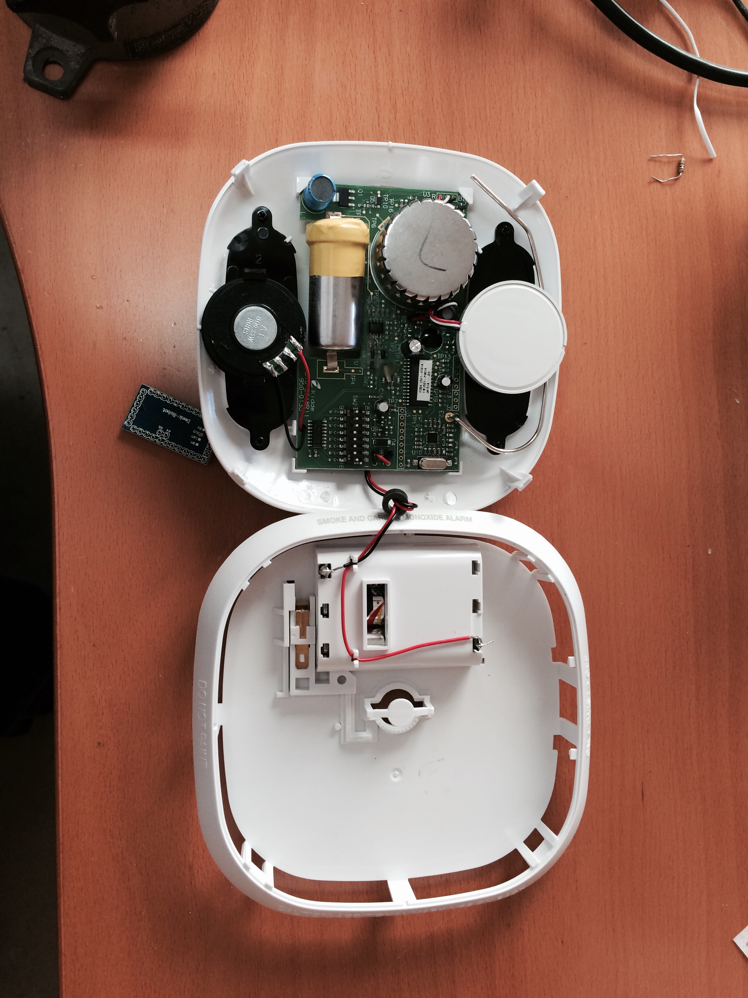
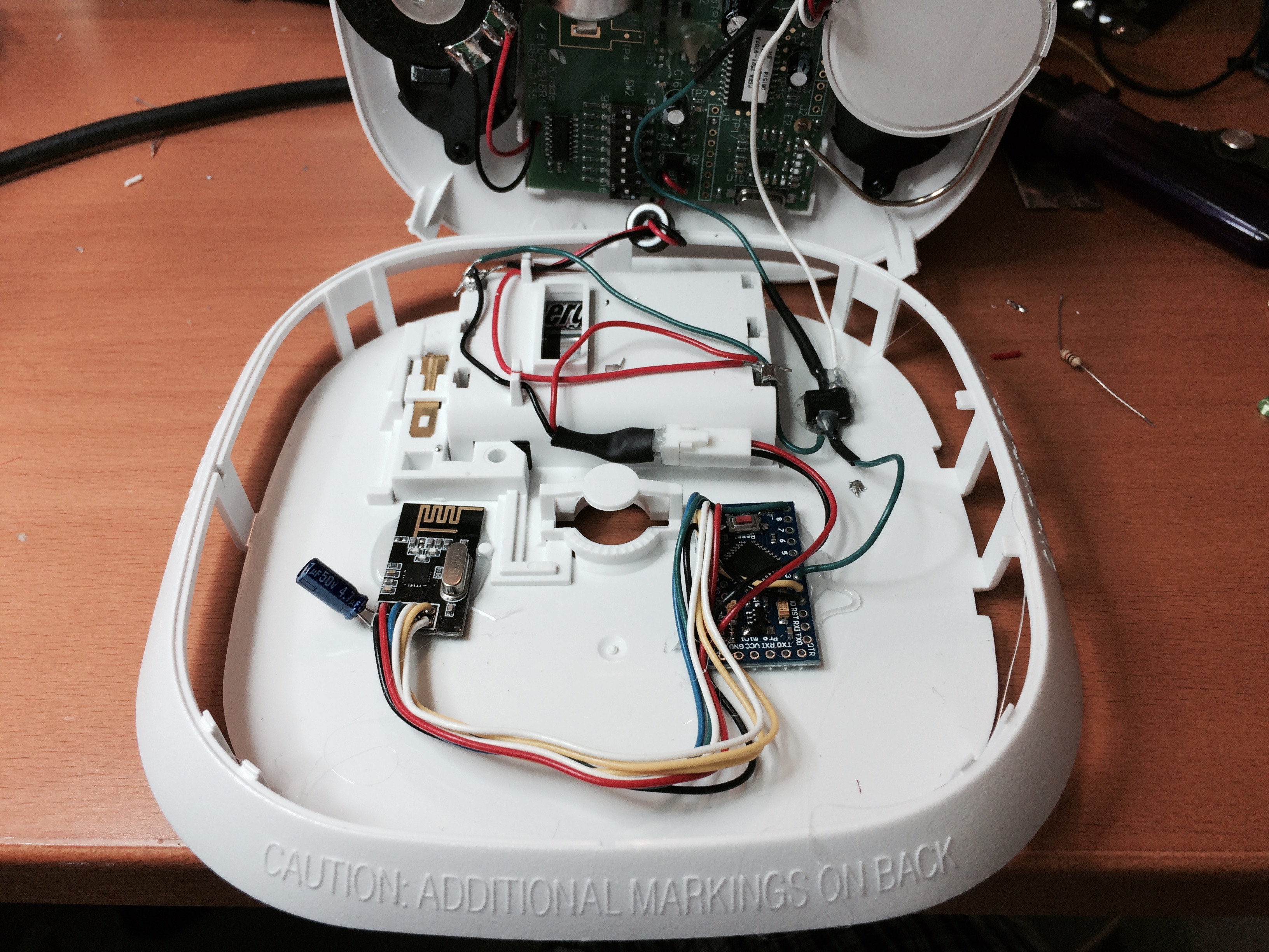
	// Based on Author: Patrick 'Anticimex' Fallberg Interrupt driven binary switch example with dual interrupts

	#include <MySensor.h>
	#include <SPI.h>

	#define SKETCH_NAME "Smoke Alarm Sensor"
	#define SKETCH_MAJOR_VER "1"
	#define SKETCH_MINOR_VER "0"

	#define CHILD_ID 3

	#define SIREN_SENSE_PIN 3   // Arduino Digital I/O pin for optocoupler for siren

	unsigned int SLEEP_TIME			= 32400; // Sleep time between reads (in seconds) 32400 = 9hrs?
	long CYCLE_COUNTER					= 3;  // This is the number of times we want the Audio Counter to reach before triggering a signal to controller.
	unsigned long CYCLE_INTERVAL		= 9; // How long do we want to watch once first detected (in seconds)
												//Adjust for your smoke detector, you want to pick up the siren signal at least 3 time to help stop false alarms.
	unsigned long CYCLE_RATE			= 90; // How fast do we want to move checking the Pin state in the Status Check (in Millis) Adjust for your smoke detector
												//Adjust for your smoke detector, you want to pick up the siren signal at least 3 time to help stop false alarms.
	unsigned long CYCLE_TIME_OKSTATUS	= 8; // How long do we want to watch for "all clear" once we have confirmed an Alarm (in seconds)
	unsigned long CYCLE_RATE_OKSTATUS	= 500; // How fast do we want to move checking the Pin state when checking for an OK status (in Millis)

	int oldValue=1;
	int value=0;


	MySensor sensor_node;
	MyMessage msg(CHILD_ID, V_TRIPPED);

	void setup()
	{
		sensor_node.begin();
		// Setup the Siren Pin HIGH
		pinMode(SIREN_SENSE_PIN, INPUT_PULLUP);
		// Send the sketch version information to the gateway and Controller
		sensor_node.sendSketchInfo(SKETCH_NAME, SKETCH_MAJOR_VER"."SKETCH_MINOR_VER);
		sensor_node.present(CHILD_ID, S_SMOKE);
	}

	// Loop will iterate on changes on the BUTTON_PINs
	void loop()
	{
		// Check to see if we have a alarm. I always want to check even if we are coming out of sleep for heartbeat.
		AlarmStatus();
		// Sleep until we get a audio power hit on the optocoupler or 9hrs
		sensor_node.sleep(SIREN_SENSE_PIN-2,FALLING, SLEEP_TIME * 1000UL);
	}

	void AlarmStatus()
	{

	// We will check the status now, this could be called by an interrupt or heartbeat
	int siren_audio_count	=0;
	long cycle_time			=0;
	unsigned long startedAt = millis();

		Serial.println("Status Check");
		//Read the Pin
		value = digitalRead(SIREN_SENSE_PIN);
		// If Pin return a 0 (LOW), then we have a Alarm Condition
		if (value != 1) {
			 //We are only going to check for status for CYCLE_INTERVAL time I think this should help stabilize Siren Sensing
			  while(millis() - startedAt < CYCLE_INTERVAL * 1000)
			  {
				  //We are going to check CYCLE_RATE fast
				  if(millis() - cycle_time > CYCLE_RATE ) {
					  // save the last time you Checked
					  cycle_time = millis();
						//We will count each time SIREN_SENSE_PIN is 0 (Alarm - LOW) for the above time and at the above rate.
						value = digitalRead(SIREN_SENSE_PIN);
							if (value != 1)
							{
								siren_audio_count++;
								Serial.print("Audio Count: ");
								Serial.println(siren_audio_count);
							}
				  }
			  }
					// Eval siren audio hit count against our limit. If we are => then CYCLE_COUNTER then lets start a loop for "All Clear" reset
					// If we continue to return an audio power hit, then we will continue to send to the controller.
					if (siren_audio_count>=CYCLE_COUNTER)
					{
						Serial.println("Alarm Detected");

						do
						{
						  //update gateway with bad news.
						  sensor_node.send(msg.set("1"));
						  Serial.println("Alarm Detected Sent to gateway");
						} while (IsAlarmAllClear()!=1);

					}
		}
		//Pin returned a 1 (High) so there is no alarm.
		else
		{
		  IsAlarmAllClear();
		}
	}

	int IsAlarmAllClear()
	// We are looking for an gap in time that we no longer see an audio power hit to the optocoupler.

	{
	 int alarmOn				=0;
	 long cycle_time			=0;
	 unsigned long startedAt	= millis();

		//We are only going to check for status for CYCLE_TIME_OKSTATUS time
		while(millis() - startedAt < CYCLE_TIME_OKSTATUS * 1000)
		{
			//We are going to check CYCLE_RATE_OKSTATUS fast
			if(millis() - cycle_time > CYCLE_RATE_OKSTATUS) {
				// save the last time you Checked
				cycle_time = millis();
				int value = digitalRead(SIREN_SENSE_PIN);
				if (value != 1) //We are still in an alarm state
				{
					alarmOn++;
				}
			}
		}
				if (alarmOn < 1)
				{
					// We don't have any sign that we are still in an alarm status
					//Send all clear msg to controller
					sensor_node.send(msg.set("0"));
					Serial.println("All Clear");
					return 1;
				}
				else
				{
					// We are still in an alarm status
					//The calling function will handle sending NOT CLEAR to controller
					Serial.println("NOT CLEAR");
					return 0;
				}

 }
Here is the wiring:

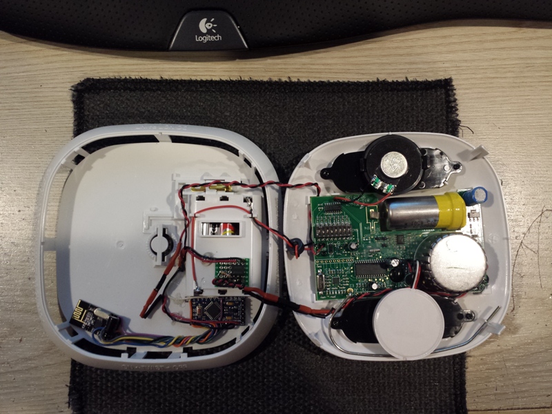
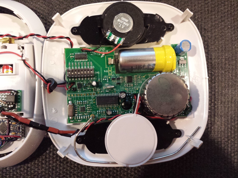
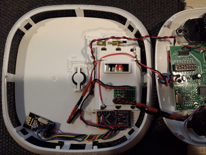
Here are some finished hardware pics:
-
Awesome job! This was on my list of things to do and you have just made it easier for me. Thanks!
It also looks like you were able to get the smoke device working, correct? If so, that's even cooler!
@petewill Thanks, and no the Vera device is not complete. I have A LOT to learn before I can make the device visual active. That said, the default Vera device that is created works; it just doesn't have any visually active changes.
The good news it AuthomationHD and ImperiHome have visually active displays that work perfectly with the default Vera device.
Hopefully that is clearer then it's written.. :-)
-
@ServiceXp said:
That said, the default Vera device that is created works; it just doesn't have any visually active changes.
you could always just add a Motion device until you learn how to mod your device...
Great job here.
-
I think it's complete.
Hardware wise this project is VERY easy to complete. The hardest part was arranging the hardware to fit in the case. The sketch on the other hand was a pain in my butt and I'm sure it's VERY inefficient, but does seem to work without ANY false alarms.
Thanks to @BulldogLowell for the help!
Mod Goals:
- Detect when the siren is powered up and transmit that "trip" to Vera (for various processes)
- Use interrupt to start Arduino with a 9 hour "heart beat".
- Utilize the detectors battery power.
Because this detector has on-board battery level checks and warnings, I don't have to mess around with building a battery circuit.
BOM:
- Pro Mini
- I'm using Optocoupler for the speaker power isolation (you could probably just sense the 3.3v speaker voltage directly).
- Kidde Detector Used (any can be used providing you have the space inside)
Here is the sketch:
	// Based on Author: Patrick 'Anticimex' Fallberg Interrupt driven binary switch example with dual interrupts

	#include <MySensor.h>
	#include <SPI.h>

	#define SKETCH_NAME "Smoke Alarm Sensor"
	#define SKETCH_MAJOR_VER "1"
	#define SKETCH_MINOR_VER "0"

	#define CHILD_ID 3

	#define SIREN_SENSE_PIN 3   // Arduino Digital I/O pin for optocoupler for siren

	unsigned int SLEEP_TIME			= 32400; // Sleep time between reads (in seconds) 32400 = 9hrs?
	long CYCLE_COUNTER					= 3;  // This is the number of times we want the Audio Counter to reach before triggering a signal to controller.
	unsigned long CYCLE_INTERVAL		= 9; // How long do we want to watch once first detected (in seconds)
												//Adjust for your smoke detector, you want to pick up the siren signal at least 3 time to help stop false alarms.
	unsigned long CYCLE_RATE			= 90; // How fast do we want to move checking the Pin state in the Status Check (in Millis) Adjust for your smoke detector
												//Adjust for your smoke detector, you want to pick up the siren signal at least 3 time to help stop false alarms.
	unsigned long CYCLE_TIME_OKSTATUS	= 8; // How long do we want to watch for "all clear" once we have confirmed an Alarm (in seconds)
	unsigned long CYCLE_RATE_OKSTATUS	= 500; // How fast do we want to move checking the Pin state when checking for an OK status (in Millis)

	int oldValue=1;
	int value=0;


	MySensor sensor_node;
	MyMessage msg(CHILD_ID, V_TRIPPED);

	void setup()
	{
		sensor_node.begin();
		// Setup the Siren Pin HIGH
		pinMode(SIREN_SENSE_PIN, INPUT_PULLUP);
		// Send the sketch version information to the gateway and Controller
		sensor_node.sendSketchInfo(SKETCH_NAME, SKETCH_MAJOR_VER"."SKETCH_MINOR_VER);
		sensor_node.present(CHILD_ID, S_SMOKE);
	}

	// Loop will iterate on changes on the BUTTON_PINs
	void loop()
	{
		// Check to see if we have a alarm. I always want to check even if we are coming out of sleep for heartbeat.
		AlarmStatus();
		// Sleep until we get a audio power hit on the optocoupler or 9hrs
		sensor_node.sleep(SIREN_SENSE_PIN-2,FALLING, SLEEP_TIME * 1000UL);
	}

	void AlarmStatus()
	{

	// We will check the status now, this could be called by an interrupt or heartbeat
	int siren_audio_count	=0;
	long cycle_time			=0;
	unsigned long startedAt = millis();

		Serial.println("Status Check");
		//Read the Pin
		value = digitalRead(SIREN_SENSE_PIN);
		// If Pin return a 0 (LOW), then we have a Alarm Condition
		if (value != 1) {
			 //We are only going to check for status for CYCLE_INTERVAL time I think this should help stabilize Siren Sensing
			  while(millis() - startedAt < CYCLE_INTERVAL * 1000)
			  {
				  //We are going to check CYCLE_RATE fast
				  if(millis() - cycle_time > CYCLE_RATE ) {
					  // save the last time you Checked
					  cycle_time = millis();
						//We will count each time SIREN_SENSE_PIN is 0 (Alarm - LOW) for the above time and at the above rate.
						value = digitalRead(SIREN_SENSE_PIN);
							if (value != 1)
							{
								siren_audio_count++;
								Serial.print("Audio Count: ");
								Serial.println(siren_audio_count);
							}
				  }
			  }
					// Eval siren audio hit count against our limit. If we are => then CYCLE_COUNTER then lets start a loop for "All Clear" reset
					// If we continue to return an audio power hit, then we will continue to send to the controller.
					if (siren_audio_count>=CYCLE_COUNTER)
					{
						Serial.println("Alarm Detected");

						do
						{
						  //update gateway with bad news.
						  sensor_node.send(msg.set("1"));
						  Serial.println("Alarm Detected Sent to gateway");
						} while (IsAlarmAllClear()!=1);

					}
		}
		//Pin returned a 1 (High) so there is no alarm.
		else
		{
		  IsAlarmAllClear();
		}
	}

	int IsAlarmAllClear()
	// We are looking for an gap in time that we no longer see an audio power hit to the optocoupler.

	{
	 int alarmOn				=0;
	 long cycle_time			=0;
	 unsigned long startedAt	= millis();

		//We are only going to check for status for CYCLE_TIME_OKSTATUS time
		while(millis() - startedAt < CYCLE_TIME_OKSTATUS * 1000)
		{
			//We are going to check CYCLE_RATE_OKSTATUS fast
			if(millis() - cycle_time > CYCLE_RATE_OKSTATUS) {
				// save the last time you Checked
				cycle_time = millis();
				int value = digitalRead(SIREN_SENSE_PIN);
				if (value != 1) //We are still in an alarm state
				{
					alarmOn++;
				}
			}
		}
				if (alarmOn < 1)
				{
					// We don't have any sign that we are still in an alarm status
					//Send all clear msg to controller
					sensor_node.send(msg.set("0"));
					Serial.println("All Clear");
					return 1;
				}
				else
				{
					// We are still in an alarm status
					//The calling function will handle sending NOT CLEAR to controller
					Serial.println("NOT CLEAR");
					return 0;
				}

 }
Here is the wiring:
Here are some finished hardware pics:
@ServiceXp Are you grabbing the 4V8 and inputting to 3V3 arduino RAW pin? Or are you grabbing the power off J3 Pin1 and 2 at 3V3? Did you make your Arduino less Power hungry i.e. remove LEDs, Regulator, and such? How is the battery life so far? Sorry lots of questions I want to build this for my whole house like 10 of them! But gotta start from some where. I'm thinking most of them are A/C powered in my house so a 5V power supply with a regulator for the detector would work also. Please Let me know how yours is working so far.
Thanks! Great Job! -
- 4v8 into RAW
- 3v3 pin to radio
- all LED's removed
- Regulator remains to power radio
I have not changed the batteries since I posted, and the heart beat is still sending every 9 hrs
@ServiceXp Cool I just tested it and was ready build my first unit. I will post after I do it tonight! Have you tried to sniff the Jumpers for signals(like the CO2 or Smoke)? You said you are using the built in battery low detection are you talking about the warning that the batteries need to be replaced locally or remote? Oh Nevermind it will alarm so you will know remote and audible siren and voice local.
The 3V3 off the board proves to be clean enough? I read somewhere that that might be a problem.
Thanks
-
Ok all is Good! I just used the octocoupler minus the perf board,also as a side note I changed the resistor you showed to a 4.7K to keep the current of the speaker from being drowned out, I also added a power header.
and here is the Modded One!
Thanks again @ServiceXp for all the hard work you did to get us this mod. Now 9 more to go! But I will wait and test this one out for a couple of months or maybe I should just build 5 more for now. Any Ideas on how to make this run on external power until power is lost?
@DrJeff Sorry about the delay.. Looks like you figured it out... :-)
You really don't need to build anymore if you are using those detectors through out the house (and they are setup interlocked), as once one goes off, they all go off and will signal to your controller that there is trouble.
RJ_Make
Hello! It looks like you're interested in this conversation, but you don't have an account yet.
Getting fed up of having to scroll through the same posts each visit? When you register for an account, you'll always come back to exactly where you were before, and choose to be notified of new replies (either via email, or push notification). You'll also be able to save bookmarks and upvote posts to show your appreciation to other community members.
With your input, this post could be even better 💗
Register Login