Skip to content
  • 0 Votes
    2 Posts
    19 Views
    OldSurferDudeO
    @nrf24_is_hard When I sent data between an Aduino and the RPi I discovered that I have to make the the receiving and the sending structs the same size AND the variables be on 4 byte boundaries. Change your char name[15] to char name[16] Another challenge is that the number of bytes of type int are different. If I remember correctly, Arduino Uno is 2 bytes and RPi is 4 bytes. To make matters worse, some compilers make the least significant byte the first byte of a word and others make it the last byte of a word. eg, sending the value 1 would be received as 16777216 (0x00000001 vs 0x01000000) There are a lot more gotcha's ;) OSD
  • 0 Votes
    3 Posts
    64 Views
    Giovanni ChivaG
    @mfalkvidd thank you very much for your quick answer! I'll look into that.
  • 0 Votes
    13 Posts
    106 Views
    zboblamontZ
    @GLAB No worries, was in a similar situation.. My perspective was on what the Node could be made to provide, not what could be done within Domoticz to address the requirement - eg Had heard of Dummy counters but had no experience nor understood their purpose, nor had ever used scripts. I had been sending a logical ON/OFF as well as a cumulative total from the Node and hit the same hair-pulling scenario as yourself. Now only the ON/OFF is sent and the short script makes the transposition within Domoticz to a dummy meter (I think kWhr) using the internal clock in Domoticz. Have fun ;)
  • Setting up the 2nd RF24 network..

    Hardware nrf24network rf24 nrf24l01
    5
    0 Votes
    5 Posts
    857 Views
    pvojP
    @yveaux thank you for letting me know about this great project! The thread is also very useful. I managed to find a relatively quiet range in channels.
  • 0 Votes
    13 Posts
    1k Views
    mfalkviddM
    @flyingdomotic I agree that references to relevant part of the datasheet for each delay would be good. Now they are just magic numbers. Without such references, understanding, reviewing, extending and maintaining the code is extremely hard. For [solved], edit your first post and change the headline (you might need to scroll up to see the headline if you are on mobile)
  • Low Power Servo Actuator

    Development servo arduino low power battery powered rf24
    8
    0 Votes
    8 Posts
    5k Views
    martinhjelmareM
    @hek Thanks for the comments. Sounds good. I'll report back when I have some progress.
  • DevDuino v2.2 with EEPROM

    Hardware devduino rf24 nrf24l01+
    10
    0 Votes
    10 Posts
    4k Views
    O
    Here is the code works with devDuino v2.2 It shows how all of the sensors on board (via com port) and also makes it possible to (expect) to download the firmware over the air. (for example through MYSController) /* This sketch is for a devDuino SN v2.2 with the support OTA http://www.seeedstudio.com/wiki/DevDuino_Sensor_Node_V2.2_(ATmega_328) and MySensors 1.5 For testing all the equipment, press the button D4 when a voltage is applied. This sketch is a modification of code written Version 1.3 - Thomas Bowman Mørch for sensor Sensebender Micro http://www.mysensors.org/hardware/micro modified 18 December 2015 by greengo */ #include <MySensor.h> #include <SPI.h> #include "utility/SPIFlash.h" #include <EEPROM.h> #include <sha204_lib_return_codes.h> #include <sha204_library.h> // Define a static node address, remove if you want auto address assignment //#define NODE_ADDRESS 2 #define RELEASE "0.01" #define TEST_PIN 4 // Button D4 #define TEMP_SENSE_PIN A3 // Input pin for the Temp sensor MCP9700 #define LED_PIN 9 // LED #define ATSHA204_PIN A2 // ATSHA204A const int sha204Pin = ATSHA204_PIN; atsha204Class sha204(sha204Pin); SPIFlash flash(8, 0x1F65); MyTransportNRF24 transport(7, 6); MySensor gw(transport); // the setup function runs once when you press reset or power the board void setup() { // initialize digital pin 9 as an output. pinMode(LED_PIN, OUTPUT); Serial.begin(115200); Serial.print(F("devDuino V2.2")); Serial.println(RELEASE); Serial.flush(); // First check if we should boot into test mode pinMode(TEST_PIN,INPUT); digitalWrite(TEST_PIN, HIGH); // Enable pullup if (!digitalRead(TEST_PIN)) testMode(); // Make sure that ATSHA204 is not floating pinMode(ATSHA204_PIN, INPUT); digitalWrite(ATSHA204_PIN, HIGH); digitalWrite(LED_PIN, HIGH); #ifdef NODE_ADDRESS gw.begin(NULL, NODE_ADDRESS, false); #else gw.begin(NULL,AUTO,false); #endif digitalWrite(LED_PIN, LOW); Serial.flush(); Serial.println(F(" - Online!")); gw.sendSketchInfo("devDuino SN V2.2", RELEASE); } // the loop function runs over and over again forever void loop() { gw.process(); } /**************************************************** * * Verify all peripherals, and signal via the LED if any problems. * ****************************************************/ void testMode() { uint8_t rx_buffer[SHA204_RSP_SIZE_MAX]; uint8_t ret_code; byte tests = 0; digitalWrite(LED_PIN, HIGH); // Turn on LED. Serial.println(F(" - TestMode")); Serial.println(F("Testing peripherals!")); Serial.flush(); Serial.print(F("-> MCP9700 : ")); Serial.flush(); if (analogRead (TEMP_SENSE_PIN),HIGH ) { Serial.println(F("ok!")); tests ++; } else { Serial.println(F("failed!")); } Serial.flush(); Serial.print(F("-> Flash : ")); Serial.flush(); if (flash.initialize()) { Serial.println(F("ok!")); tests ++; } else { Serial.println(F("failed!")); } Serial.flush(); Serial.print(F("-> SHA204 : ")); ret_code = sha204.sha204c_wakeup(rx_buffer); Serial.flush(); if (ret_code != SHA204_SUCCESS) { Serial.print(F("Failed to wake device. Response: ")); Serial.println(ret_code, HEX); } Serial.flush(); if (ret_code == SHA204_SUCCESS) { ret_code = sha204.getSerialNumber(rx_buffer); if (ret_code != SHA204_SUCCESS) { Serial.print(F("Failed to obtain device serial number. Response: ")); Serial.println(ret_code, HEX); } else { Serial.print(F("Ok (serial : ")); for (int i=0; i<9; i++) { if (rx_buffer[i] < 0x10) { Serial.print('0'); // Because Serial.print does not 0-pad HEX } Serial.print(rx_buffer[i], HEX); } Serial.println(")"); tests ++; } } Serial.flush(); Serial.println(F("Test finished")); if (tests == 3) { Serial.println(F("Selftest ok!")); while (1) // Blink OK pattern! { digitalWrite(LED_PIN, HIGH); delay(200); digitalWrite(LED_PIN, LOW); delay(200); } } else { Serial.println(F("----> Selftest failed!")); while (1) // Blink FAILED pattern! Rappidly blinking.. { } } }
  • 0 Votes
    4 Posts
    2k Views
    T
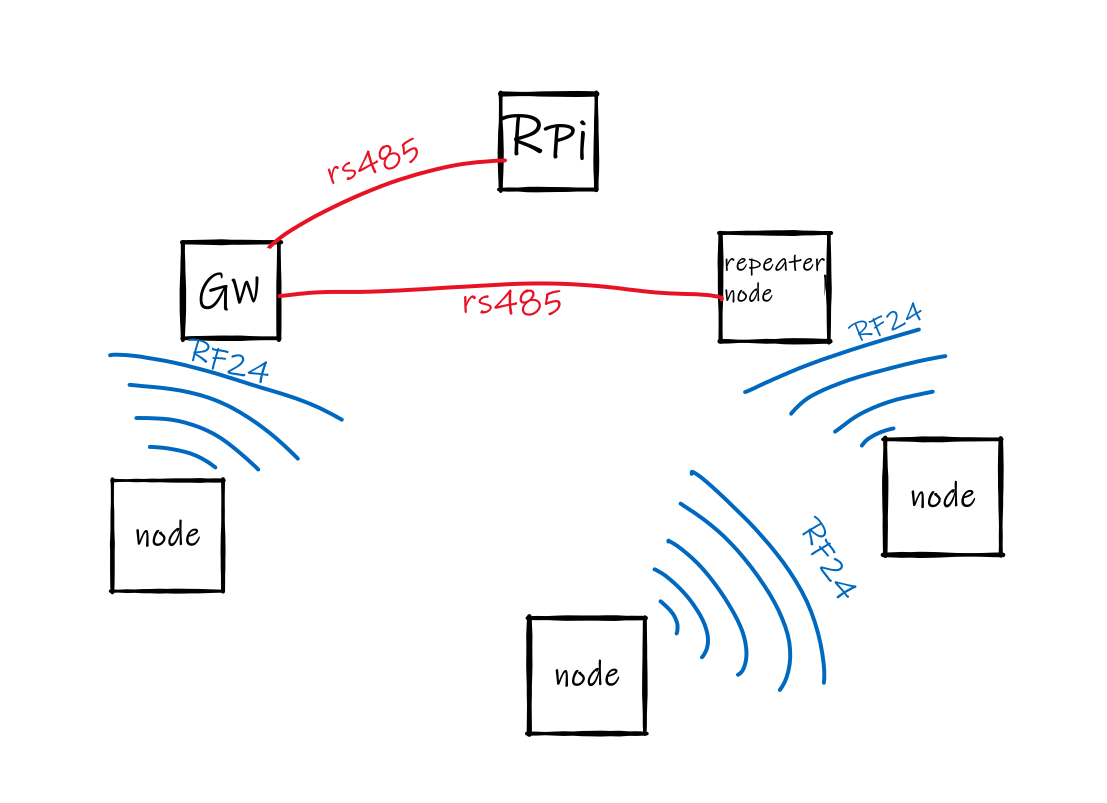
    In general the readings will not be underwater. At best, I think we could cover a foot or two with RF before the signal fades to noise. Even though sound travels well underwater, RF at these frequencies do not. But what we hope to do, is take them out, leave them sealed and then download the information via a stored CSV file. That is the part we are struggling to code with right now. Sensor arrays: We are building one to ride on surfboards that has gyrometric and accelerometric capabilities as well as temperature using a sinple DS18B20 tail into the water. This is for a social science project. However, a more involved project involves pressure, temperature and conductivity (this is the hardest one to reliably measure with affordable parts). the whole shebang is used to monitor streams, rivers and as of late wells to assess the impacts of salt run-off and ground water infiltration. Currently the commercial units cost $1500 plus a reader per single instance. If we can get this to work we can install 10x the number of sensors and engage citizens and science teachers in the building of our network. Right now, I am trying to make it easy to get files out without the help (who might be 10 or not technical) having to open the units and reassemble them properly. Thus the WIFI.
  • 0 Votes
    3 Posts
    4k Views
    hekH
    @Dirk_H There isn't any limit. But keep the number of hops low if possible.
  • Sample Door SW does not compile !

    Troubleshooting arduino rf24 compilation
    3
    0 Votes
    3 Posts
    2k Views
    m26872M
    I compile the example sketch fine with IDE 1.5.7. Do you have uncommented the #define SOFTSPI in RF24_config.h for some reason (eg programming your gateway)?. If so comment it back again.
  • Full-Duplex Network

    My Project rf24 nrf24l01+ full duplex
    11
    0 Votes
    11 Posts
    14k Views
    S
    I solved it ...was quite easy ... thanks anyway... I'll post the code soon since it is not on web till now..

23

Online

11.7k

Users

11.2k

Topics

113.1k

Posts