nRF24L01+ Communication Failure: Root Cause and “Solution”
-
Project Background
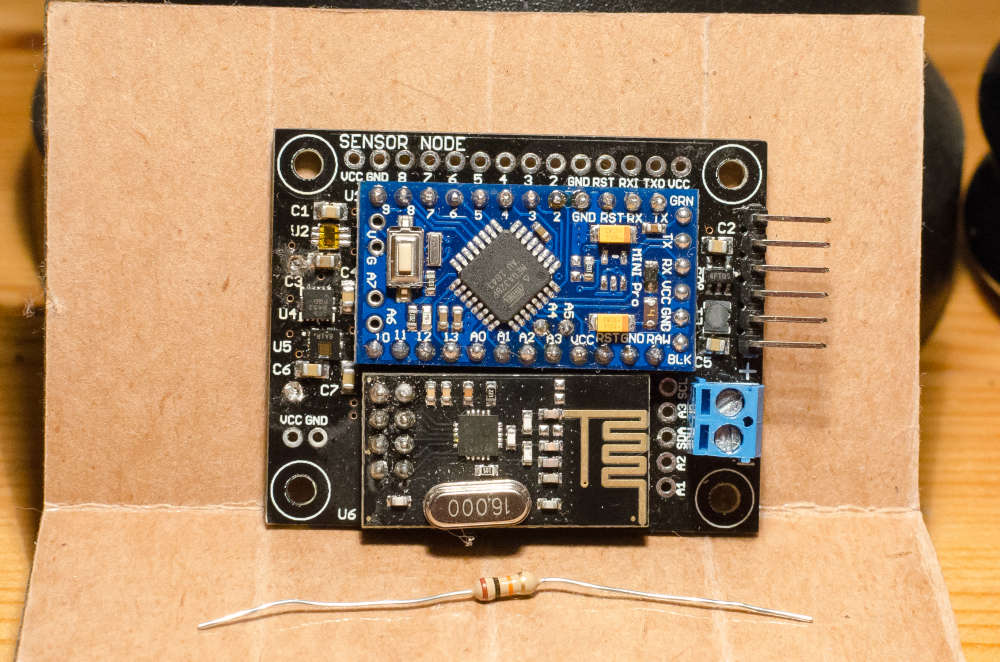
First, some background information on the project. We had prototyped an arduino and nRF24L01+ based sensor board using mysensors and home assistant. The main goal of this board was whole home temperature, humidity, and light level monitoring. The prototype was built from stand alone protoboards, breadboards, wires, etc. It worked great, so we decided to make a custom PCB that would have a socket for the arduino pro mini, a socket for the nRF24L01+ boards, and all of the other circuitry (sensors, power supply, etc).
Image 1: Sensor Board! (Resistor for scale)
Problem
After building up a number of the “New and Improved!” custom PCBs, we noticed that some of them just didn’t work very well. We could read the data from all the sensors via the arduino, but they would fail in one of a few ways:
- Not present with the gateway / Nothing seemingly happens.
- Present but have terrible “message loss”. The original behavior was intermittent updates from the sensors board. To determine our “message loss” we created a debug program that would send a finite number of messages from the sensor board with an ack request and wait for the ack with a time out. The final “message loss” was (number of messages sent ) - (number of messages ack’d).
Initial observations and debugging (in no particular order of desperation).
- More bulk capacitance on the nRF24L01+ board. No luck. (BUT THE FORUMS PROMISED)
- Changing power source (Batteries, Benchtop, etc) didn’t change behavior.
- Changing the nRF24L01+ on our gateway (Raspberry Pi) didn’t change behavior.
- A “problem” sensor board got “better” when we swapped out the nRF24L01+ board. (AHA! It must be the questionably authentic nRF24L01+ boards we ordered). So, we built a sensor board with a header socket so we could quickly screen/test all of our nRF24L01+ boards. This was ineffective and led to confusion (Wait, I thought you said this nRF24L01+ board worked?) as some nRF24L01+ boards worked in the screening unit, but then didn’t work in their final sensor board.
- Changing distance between sensor boards and gateway didn’t change anything in a meaningful or coherent way.
- Accidentally holding our thumb on the antenna changed the behavior. (Hey, wait, what just happened? It’s working! Wait.. no it isn't’.. What?)
- Changing the data (symbol) rate of the nRF24L01+ board changed the behavior, but didn’t fix anything.
- Changing the SPI speed also changed the behavior, but didn’t fix anything.
- Changing the channel on the nRF24L01+ board helped at one person’s house but not other project member’s houses.
- Manipulate ground planes on sensor board near antenna. (dremeled away).
- Using the previously mentioned sensor board with a header socket, we observed that almost any nRF24L01+ board worked when cabled (~6 inches) rather than directly plugging into the sensor board. (BUT WHY?????)
{A year, a kid, and job changes later}
Eventually, we decided the project had languished long enough. Enough sleep had been lost! We were going to figure out this problem!
How
Throwing stuff at the wall to see what stuck wasn't working, so we decided we needed to get serious and capture the wireless data. We borrowed a software defined radio (SDR) to capture the 2.4GHz spectrum with the intent of first demodulating the signal to see if that showed the smoking gun (It did but we didn't realize it at the time).
Image 2: Demodulated Signal (Hey, that looks like a digital signal!)
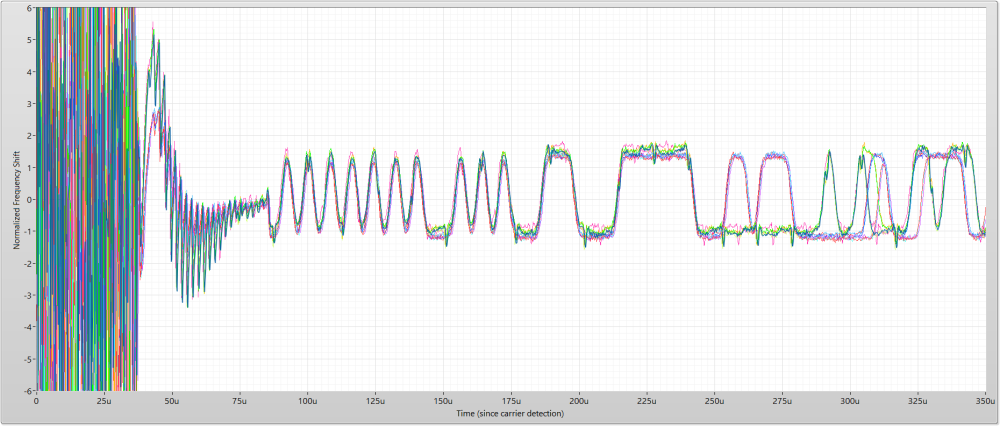
Now that we can see the data to train on, we can decode the nRF24L01+ packet to see what’s going on. Specifically, the goal was to see if a packet was “good” or “bad” and our criteria for a “Good” packet was the Cyclic Redundancy Check (CRC) passing. (See image below).
Image 3: Decoded NRF24L01+ Packet with CRC Check.
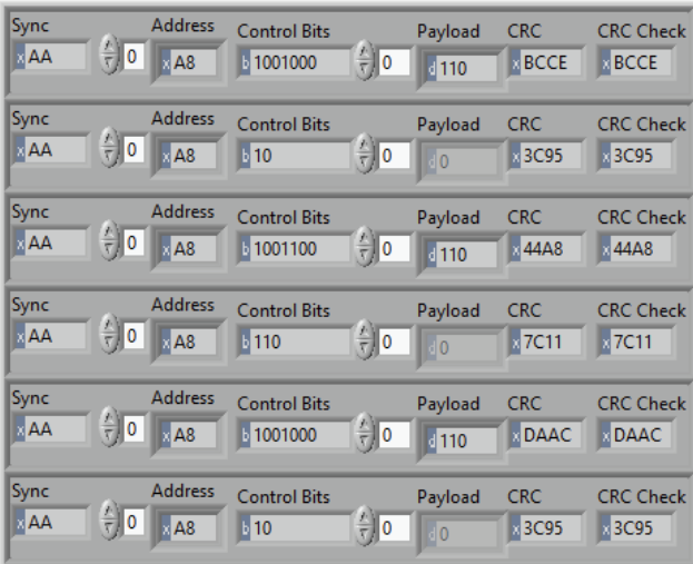
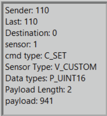
Full of excitement and curiosity, we wielded our newfound RF power to decode the MySensors Payload as well (see Image 4 below) This didn’t prove to be very helpful for debug purposes, but it was interesting.
Image 4: Decoded Mysensors Payload
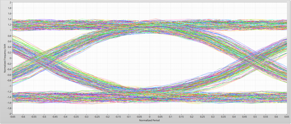
Now that we can see “passing” and “failing” packets, we know we are on the right track. However, we need to measure the transmission “quality” beyond just pass/fail. Since the transmission is just binary data (using Frequency Modulation) we can parse the data to assemble the data Eye pattern (Image 5 below).
Image 5: Impressively “Bad” data Eye pattern
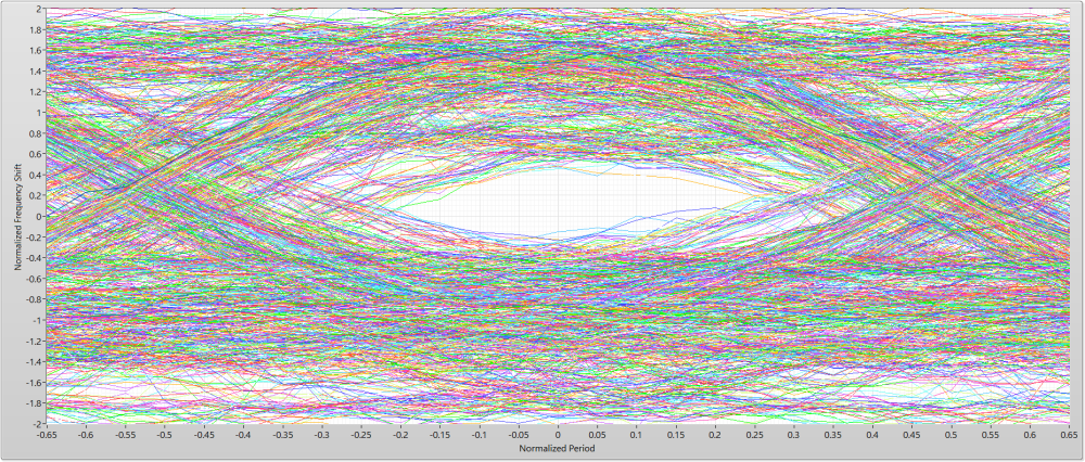
I think I found the problem… But what is causing the Eye to close (good data Eye patterns are wide open in the middle)? Also, sometimes I get really good looking data Eyes! What is going on?!? Let’s have a closer look at a bad transmission. Images 6 and 7, shown below, are single transmissions taken from the multiple transmissions, previously shown in image 2.
Image 6: A closer look at a single “bad” demodulated transmission (Wow, that’s bad!)
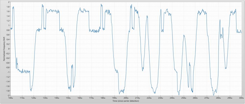
Image 7: A closer look at a single “good” demodulated transmission (That looks perfect! How is this the same board?)
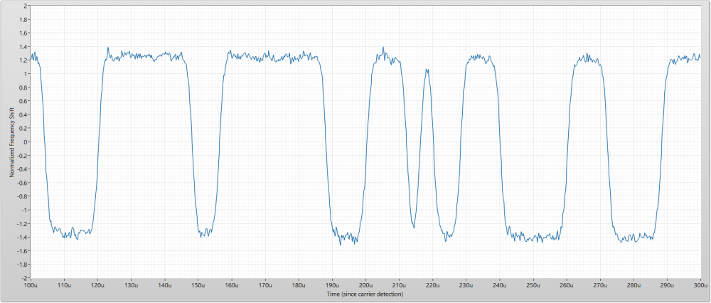
Comparing Images 6 and 7 is very interesting, we might be looking at the root cause here. The bad transmission looks like it has an “other” digital signal riding on top of it. What is going on during the nRF24L01+ transmission?
We decided to grab a bus analyzer and record communication on the SPI bus during a transmission (see Image 8 below).
Image 8: A Bus Analyzer capture during transmission (Wait a minute! That looks familiar!)

It seems strange that the SPI bus is constantly active during transmission. What is MySensors doing? Grab the shovel...
Digging into the RF24.cpp file shows the RF24_getStatus() function called continuously at line 326. This pumps the SPI interface (sends 0xFF) to read the status register of the nRF24L01+ and see if the transmission is complete.
A snippet of code from Github (“MySensors\hal\transport\driver\RF24.cpp”) shown below starting at line number 321
Code Snippet 1
// go, TX starts after ~10us, CE high also enables PA+LNA on supported HW
	RF24_ce(HIGH);
	// timeout counter to detect HW issues
	uint16_t timeout = 0xFFFF;
	do {
		RF24_status = RF24_getStatus();
	} while  (!(RF24_status & ( _BV(RF24_MAX_RT) | _BV(RF24_TX_DS) )) && timeout--);
	// timeout value after successful TX on 16Mhz AVR ~ 65500, i.e. msg is transmitted after ~36 loop cycles
	RF24_ce(LOW);
	// reset interrupts
	RF24_setStatus(_BV(RF24_TX_DS) | _BV(RF24_MAX_RT) );
	// Max retries exceeded
	if(RF24_status & _BV(RF24_MAX_RT)) {
		// flush packet
		RF24_DEBUG(PSTR("!RF24:TXM:MAX_RT\n"));	// max retries, no ACK
		RF24_flushTX();
We have found our smoking gun!
“Solution”
But wait! Don’t we need to check the transmission status? The answer is: kind of, but not like this. Ideally, the nRF24L01+ signals the gateway/sensor when transmission is finished and transmit success/failure can be determined by checking the transmission status. (Alternatively, you could just place a time delay after TX Enable that waits the max duration of your transmission and retries. However this is application dependent, and may not fully resolve the issue if you have many retries).
A way that this could be achieved is through the use of the handy IRQ (Interrupt Request) line on the nRF240L01+. MySensors can make use of the IRQ line, however it does so in a different way than we want. MySensors uses the IRQ to signal the message handler to pull received messages from the nRF24L01+ internal FIFO to prevent overflow. This can be important for high traffic networks but sadly doesn’t help our situation.
We decided to look at the datasheet (Image 9 below) for the nRF24L01+ for potential solutions and found a workaround.
Image 9: Snippet from nRF24L01+ datasheet describing what the IRQ line can be attached to
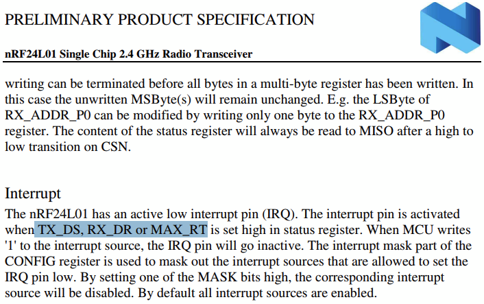
Great! TX_DS (TX Data Sent) and MAX_RT (Max TX retries reached) are the two flags we want to monitor to remedy our issue. It so happens, the IRQ line is setup to respond to these flags by default already! However, MySensors does not listen to the IRQ line during transmission (as shown in Code Snippet 1). So, let’s fix that!
Below you can see the code with our “fix”.
Code Snippet 2
// go, TX starts after ~10us, CE high also enables PA+LNA on supported HW
	RF24_ce(HIGH);
	// timeout counter to detect HW issues
	uint16_t timeout = 0xFFFF;
	do {
		//RF24_status = RF24_getStatus();
		RF24_status = hwDigitalRead(MY_RF24_IRQ_PIN);
	} while  (RF24_status && timeout--);
	//}while  (!(RF24_status & ( _BV(RF24_MAX_RT) | _BV(RF24_TX_DS) )) && timeout--);
	// timeout value after successful TX on 16Mhz AVR ~ 65500, i.e. msg is transmitted after ~36 loop cycles
	RF24_status = RF24_getStatus();
	RF24_ce(LOW);
	// reset interrupts
	RF24_setStatus(_BV(RF24_TX_DS) | _BV(RF24_MAX_RT) );
	// Max retries exceeded
	if(RF24_status & _BV(RF24_MAX_RT)) {
		// flush packet
		RF24_DEBUG(PSTR("!RF24:TXM:MAX_RT\n"));	// max retries, no ACK
		RF24_flushTX();
With the fix shown above, we recaptured transmissions from the same hardware shown in Image 5. Look how nice that data Eye pattern is! (as shown in Image 10 below).
Image 10: Data Eye pattern with transmission IRQ fix
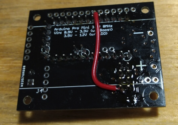
WOW! That is an unbelievable improvement! Thankfully, all those “bad” or “questionable” sensor boards now work like a charm! They all successfully complete presentation and have very low message loss. Sadly, our custom PCB did not pin out the IRQ line so we had to solder a wire from IRQ to an unused pin.
Image 11: Workaround wire
Also, out of the 20ish nRF24L01+ boards all but one are the “clones” with the Shockburst bit inversion. So, this problem may not be as pronounced on genuine or “better clones”. However, it is generally good practice to quiet or mute unnecessary digital communication during transmit/receive if possible.
HALP
We are hardware folk by trade and things like ‘GitHub’ or “software best practices” are not our forte. (For Example, using a bus analyzer to sniff the SPI lines was much easier than digging into the code stack). If somebody was so willing, submitting this fix (or hopefully a better one!) would be great.
-
@odritter interesting analysis and fantastic writeup. I'll have to learn more about looking at data Eyes, seems like a very useful tool.
The placement of the nrf's antenna on the board is very unusual. Most boards have the antenna away from surrounding conductive material (see https://www.openhardware.io/view/4/EasyNewbie-PCB-for-MySensors for example)
How are the SPI lines placed on the board? Do they pass close to the antenna? or close to any other line that is not driven, which passes close to the antenna?
-
this is great info, this could potentially help a lot of people on this forum
-
@odritter - Superb write up and sleuthing! - Thanks for sharing the results and findings.
Do you believe that the interference is caused internally in the nrf24 chip due to spi activity during tx mode, or possibly power rail 'ringing' due to the spi being used at the same time as Tx is happening? - I would guess the former, but at such low voltage and currents strange things can happen....

-
@mfalkvidd Hello! I am one of the other "we" mentioned in this post. I don't have access to the layout files at this moment, but I checked the Gerber files and none of the SPI lines are routed under (or near) the antenna. They are also not routed near any other lines that route under the antenna.
"The placement of the nrf's antenna on the board is
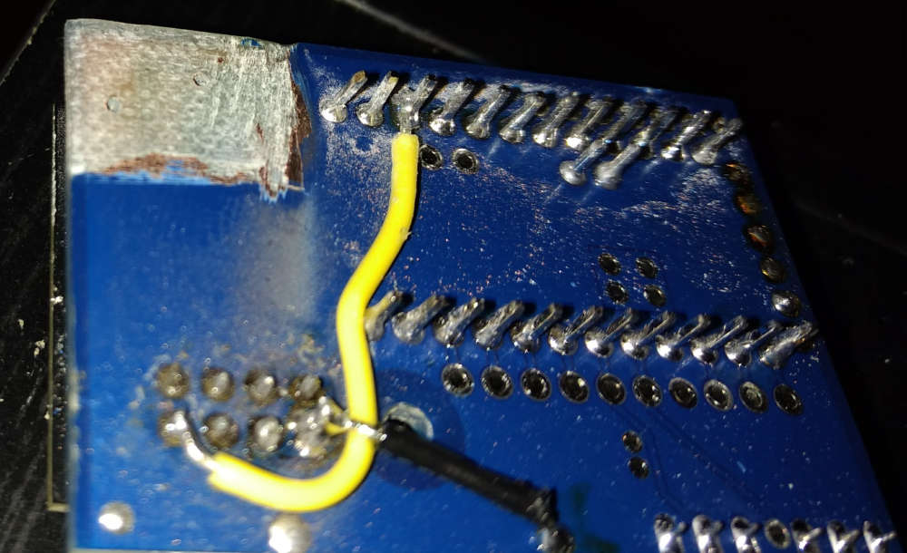
very unusual." BadYeah..... In our original goal/planning for this sensor board, we were going for a tight footprint that would sit inside a 3D printed enclosure easily and didn't think about the antenna being parallel to the PCB underneath it. Once we started having issues, we used a dremel to remove all the copper we could from the board below the antenna, but that didn't change the behavior we saw.
Technically, we did that dremel experiment on a different board (we made two different designs) that was showing the same issue. Below, you can see an image of that experiment.
-
@skywatch I don't know for sure where the interference is happening. I do know it isn't due to power supply bounce (at least on a board level) as I placed a variety of low ESR ceramics caps directly on the nRF board pins with zero change.
My guess is the interference is primarily internal to the chip but I believe there is also a board level interaction somewhere (based on observed changes during experimentation). I did experiment slowing down the SPI lines coming from the Arduino board (series resistor with shunt cap at the Arduino pin) and it seemed to help a little bit but nowhere near the improvement with complete SPI muting. I would have done the same thing on the nRF board itself for MISO but the line pitch on that board is beyond my patience (and shaky hands). If SPI muting isn't a viable option for you for some reason, more experimentation might be needed to determine exactly where the problem is occurring.
-
@odritter Thanks - I have already put your changes into my RF24.cpp and will try it out later on.
-
@odritter What puzzles me is that the interference in image 6 apparently isn't always present (see image 7), although the behavior of the MySensors stack is always identical (see image 8 and the matching code snippet 1).
Do you see a pattern when it is present and when not?Also, switching to using the nRF24 interrupt line will break MySensors for a lot of (existing) boards, that don't have the IRQ line connected.
So, if we decide to add a silent period to the stack, we also need a non-IRQ implementation based on e.g. a delay.
-
Yes breaking the sketches for 90% or more of MySensors users (since non-irq is the default setup) would be very bad. But we should be able to use irq in case the user has defined MY_RF24_IRQ_PIN (just like we already do for RX).
-
Here is a modified RF24 stack with (among other little changes) a waiting period and no IRQ line (as @Yveaux suggested) for testing: https://github.com/tekka007/MySensors/tree/OptimizedRF24polling
Using the previously mentioned sensor board with a header socket, we observed that almost any nRF24L01+ board worked when cabled (~6 inches) rather than directly plugging into the sensor board. (BUT WHY?????)
Is this setup referring to image 7?
-
Great info, and very well written!!! Thanks for sharing.
-
@Yveaux To be clear, I realize my code snippet "fix" would break anyone who doesn't already have the IRQ hooked up. This is where we are asking for a contributor more experienced with generalizing to the MySensors library and looking for #defines or such to play nice.
As for what is different between image 6 and image 7 I admit our description in that section gets a little hand wavy for brevity. Image 7 is an auto-ACK from the nRF24L01+ ShockBurst where Image 6 is an outgoing message. You can see evidence of this in image 3 where outgoing messages (like image 6) have a payload (containing MySensors info) and auto-ACKs have no payload (shown as a grey'd out array).
Once I saw that the hardware transmission can be pristine it started me thinking what was so different between a normal message and an auto-ACK. SPI communication.
A word of caution reading too much into early debug steps mentioned (just before image 2). We decided to include these to give background information on what kinds of troubleshooting steps we tried. Some were tried out of sleep deprived desperation and what appeared to "fix" the problem at the time may have only modified the conditions that didn't work. We were not into "rigorous testing mode" at this point in time. We were blindly stabbing in the dark hoping something would work. Additionally, these early debug steps were done without any knowledge of other spectral content in the environment. Once we started using the SDR we observed the spectrum first and moved the nRF channel in a clear and free band to ensure our measurements were only of the nRF boards.
-
@tekka I peaked at the delay you added to the RF24.cpp file. It looks like your calculation is not considering auto-ACK unless I am missing something. I have given some thought to what I think needs to be considered to completely avoid all possible transmissions. See below
optimal delay with ShockBurst = TX state transition delay + (nRF packet length * DataRate + auto-ACK timeout) * (ACKretries + 1)
optimal delay without SB = TX state transition delay + nRF packet length * DataRateThe problem I ran into doing a static delay is that the delay time can get quite large if considering ACK retires making the system very slow. Reducing the amount of polling should help interference even if all SPI communication isn't avoided during every possible transmission. I would definitely prefer the IRQ line used if defined and if not then use a delay (either with or without retires in mind).
-
@odritter said in nRF24L01+ Communication Failure: Root Cause and “Solution”:
it started me thinking what was so different between a normal message and an auto-ACK. SPI communication.
And the all important fact that the ack message on air comes from the receiving node, instead of the sending one.
My gut feeling tells me you are masking a hardware (design) flaw with software. If it helps in your case, good for you, but I'd like to understand it completely before absorbing it in the stack.
-
@tekka I have been testing this (2.3.2b) on a node for the last 9.5 hours and so far no problems.
I will probably flash the GW with this today and see how that goes, not expecting any issues though!

One question though..... Does this 'fix' also apply to when the nrf is in Rx mode as well? If there is no spi activity during Rx then I guess it's a moot point. But I'd be interested in the answer.
-
This post is deleted!
-
@yveaux I agree this fix may be covering up a problem in our design. As @mfalkvidd mentioned in his post we did put the antenna in an unusual location (not ideal). So it is entirely possible our problems are caused by the antenna placement, nRF clones, or something else entirely. However, we believe we are not alone in the issues we encountered or any design flaw we made.
That being said, constantly polling during TX transmission should be avoided as it is unnecessary. MySensors can calculate how long a transmission should take and hold off for a least the first (or all possible) transmission(s). Implementing a delay should be minimal risk and can only benefit. Implementing the IRQ is more involved to implement properly and higher risk (though I think worth it).
-
@skywatch This fix only applies to the TX for three reasons.
- Our method for measuring transmission quality can only observe TX (not RX) so we would need a different way to assess RX
- TX timing is well known from start to finish so muting the communication while it is happening is relatively straightforward. RX is a different story
- MySensors already implements IRQ for RX and likely already gains whatever benefit there is to be had limiting communication during RX (though I didn't look into this extensively to confirm)
I am open to ideas on how to assess the RX side if anyone has any suggestions. However for us, implementing the IRQ fix for TX made our boards go from barely working to working like a champ!
-
@odritter Thanks for the clarification! - I learn something new (again)...

My question was based on the fact that if enough energy is present in the spi signal to imprint on the Tx output, then it would be even worse for the Rx side as the levels of signal received would be much lower than anything transmitted.
-
@odritter said in nRF24L01+ Communication Failure: Root Cause and “Solution”:
constantly polling during TX transmission should be avoided as it is unnecessary
There is no mention in the nRF24L01+ datasheet of (potential) issues caused by SPI transfers during TX, so where is your statement based on?
-
@yveaux I would be happy to provide our schematic and layout details if you think it would be helpful in identifying the hardware design flaw we made. If there is something we could do to fix this with a board change, that would be interesting to know/consider. (Especially if it ends up being mistake that is commonly made by others using who are also using the nRF24 Board).
Alternatively, it could be an issue with our specific nRF24L01+ boards. While we did order some from Amazon and some from AliExpress, out best guess is that they are all counterfeit/clones. If you know of a source where we could order a board that in confidently authentic, that would be an interesting experiment as well.
-
@ben036 I would certainly like to have a look at your design files.
You could give Ebyte modules a try : https://forum.mysensors.org/topic/9668/cdebyte-s-new-nrf24-modules-are-great-and-cheap
I have very good experience with these, and are probably using authentic nrf24's
-
I've uploaded our Eagle PCB files as well as a few PDFs/PNGs of the schematic/layout for quick viewing.
Thanks for the tip on the other nRF24 board to try.
-
@yveaux My statement is based on the assumption that everything can interfere with your desired signal. It's just a matter of how much. It's very possible that genuine nRF boards are less susceptible to the interference we have shown. However, all the nRF boards we have are suspected clones so I do not have a way to direct compare clone vs genuine (unless we purchase from the Ebyte link you provided).
I have provided a link below to a public application note I came across that provides some background information on sources of interference and how it impacts your desired signal/receiver. Unfortunately it gets very technical at times and assumes a large amount of base RF knowledge so its usefulness may be limited. Nonetheless, I thought I would share if anyone was interested.
Testing and Troubleshooting Digital RF Communications Receiver Designs
The nRF uses a sampled IF receiver as described in section 1.2.2 and similar
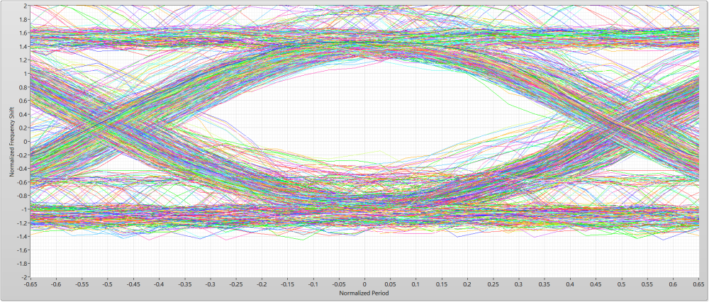
to what is shown in figure 4. Section 3.2.2 covers some interfering signals but mostly talks about more complex modulation schemes than the nRF uses.I went back and did an additional experiment using only our Gateway and the Software Defined Radio (SDR) to measure interference on something other than our sensor PCB.
My setup:
Gateway=RaspberryPi 3 with cabled nRF24L01+ hanging out in free space
SDR=USRP B210 with 2.4GHz Vertical antenna
Gateway and SDR placed about 2 feet apart in the middle of a roomGateway transmitted 16 packets for both graphs. The only difference between the two graphs: upper graph constantly polls TX status where the lower graph uses the IRQ line to wait for completion. The physical hardware setup was unchanged between the two measurements.
TX Status Polling
IRQ Wait
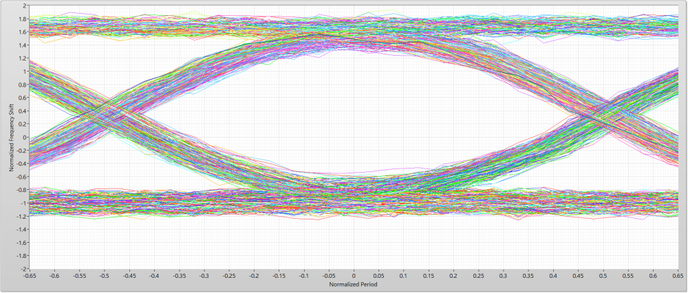
These data Eye patterns were taken with a single nRF board (in contrast, the Eye patterns included in the original post are a composite of 10 different nRF boards)
-
@skywatch said in nRF24L01+ Communication Failure: Root Cause and “Solution”:
@odritter Thanks for the clarification! - I learn something new (again)...

My question was based on the fact that if enough energy is present in the spi signal to imprint on the Tx output, then it would be even worse for the Rx side as the levels of signal received would be much lower than anything transmitted.
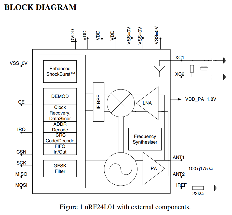
It certainly is possible the Rx side could be even worse. However, it strongly depends on where the interference is coming in. For instance, if the interference happened before the Low Noise Amplifier (LNA) then it would very likely be just as bad or even worse. However, if the interference happened after the LNA it may not have anywhere near as much impact since the signal should be much larger. Though, if the interference impacted the digitization (not really shown in the block diagram explicitly) then it would likely have a significant impact.
Thinking about the TX side of things, the interference is very likely occurring before the modulator (to the left of the PA) since I can "see" the SPI interference with the SDR after it has been demodulated. I have included the nRF block diagram from the datasheet below for reference.
-
@yveaux said in nRF24L01+ Communication Failure: Root Cause and “Solution”:
@odritter What puzzles me is that the interference in image 6 apparently isn't always present (see image 7), although the behavior of the MySensors stack is always identical (see image 8 and the matching code snippet 1).
Do you see a pattern when it is present and when not?Also, switching to using the nRF24 interrupt line will break MySensors for a lot of (existing) boards, that don't have the IRQ line connected.
So, if we decide to add a silent period to the stack, we also need a non-IRQ implementation based on e.g. a delay.Indeed, the RF Nano has no connected IRQ pins (and uses the NRF24 non-plus version..).
Although it may be unrelated, it's fascinating that this is another instance of MySensors being 'too fast', and 'needing a delay' to work better.
-
@alowhum said in nRF24L01+ Communication Failure: Root Cause and “Solution”:
MySensors being 'too fast', and 'needing a delay' to work better.
Let's not jump to conclusions too fast!
So far there's only measurement data of one case where reducing SPI traffic during TX appears to reduce noise; this makes it very likely that the issue is hardware related (SPI lines run directly below the nRF24 board, the nRF24 board is placed next to the Pro Mini SPI lines (pins 10-13) and nRF24 modules are of questionable origin).
The fact that increasing the distance between nRF24 and board by jumper wire improves the transmission success rate is a clear indication this issue is hardware related.Still, reducing potential disturbances during transmission and reception is important, especially if all MySensors users can potentially benefit from it with no or minimal penalty.
The MySensors stack however needs to support different hardware variations, with and without IRQ line connected.
The TX case with IRQ connected is trivial to solve, when IRQ is not connected is less trivial IMHO.
When using nRF24 with hardware ACK the actual TX time is not known upfront due to potential retries; we can only calculate a lower and upper bound.
Always silencing SPI communication for the upper time bound makes the node slow, shorter wait times require polling the nRF24 over SPI, thus introducing potential disturbance. The patch by @tekka reduces the polling rate and limits the upper bound (the number of hardware ACK retries), still it delays the TX time compared to the latest 2.3 release implementation.
Another solution could be limiting the SPI clock rate during the TX polling time, which also potentially improves RX polling.As always, there is no one size fits all solution

@odritter MySensors Core team has a number of SDRs and genuine nRF24's at their disposal. Do you have a description how to derive the eye pattern so others can replicate your setup?
-
@Yveaux Point taken.
I also agree that it should still work on non-IRQ scenario's, as that's pretty much my scenario now that I switched to the RF Nano.
Out of curiosity: what would be 'slow' in this scenario? Are we talking milliseconds? Hundreds?
And could this issue be related in any way?
-
@alowhum said in nRF24L01+ Communication Failure: Root Cause and “Solution”:
Out of curiosity: what would be 'slow' in this scenario? Are we talking milliseconds? Hundreds?
As always; it depends on a number of things, e.g. radio bitrate, maximum number of retries, message length. I would have to do some calculations to get an indication.
And could this issue be related in any way?
No. I suspect #941 and #1134 are related.
-
@alowhum
for older nodes, it would need retrocompatibility, but imho, when you get started in MySensors, it's bad hardware choice to not connect the radio irq signal. It's also mentioned in MySensors doc it's better to use it.Why someone wouldn't like better communication for his HA??
to be precise why someone in 2019 would like to use nrf24+low 328p ?

With irq events instead of always-polling, you get queue management for messages. And also smoother processing, better states sync, more reactive just in time, not delayed or at the wrong moment, using resources only when needed.
So,to start out on the right foot , I would strongly advice people/newcomers to connect irq when possible, and for new nodes (it's mandatory for rfm69).
-
@yveaux I can certainly provide details for others to replicate. For completeness I am including details beyond just Eye diagram creation. See below
My setup:
- nRF24L01+ (clone)
** #define MY_RF24_PA_LEVEL RF24_PA_HIGH
** #define MY_RF24_DATARATE RF24_250KBPS
** #define MY_RF24_CHANNEL 30
** #define MY_RF24_IRQ_PIN 4 - SDR: USRP B210 with 2.4GHz vertical antenna
** 5MHz bandwidth centered at 2.43GHz (for channel 30)
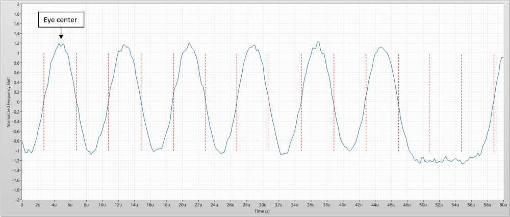
** Eye diagrams require oversampling to build a meaningful eye. I would recommend a minimum 10x oversampling if possible (5MHz BW at 250KBPS yields 20x) - Processing:
** Capture waveform with desired transmission (my setup can't trigger on anything specific, so I looked at signal power to trim down the record)
** Detect and remove carrier frequency offset - I used "0xAAA8" as a sync word
** Perform FM demodulation normalizing to expected frequency shift (±160kHz at 250KBPS)
** Find the center of the eye - this is done by looking for the location with the highest correlation to the sync word (or can be manually found)
** To build the Eye diagram, "chop" up the waveform at the crossing points which are located at ±(0.5*OversampleRate) samples from Eye center (±10 samples in my case)
** Overlay resulting waveforms on top of one another to form the Eye diagram
See image below for demonstration. Dashed red lines are where the waveform should be chopped:
I used LabVIEW with the Modulation Toolkit to perform my measurements. I can provide my code if helps though I suspect you probably use GNU Radio. I can provide additional details if something isn't clear or I left something out.
What metric do you currently use to measure link quality?
- nRF24L01+ (clone)
-
@odritter said in nRF24L01+ Communication Failure: Root Cause and “Solution”:
I suspect you probably use GNU Radio.
That's correct. To be frank, I was hoping for a simple gnu radio script that I could just run to get the pattern out. There is manual work and LabVIEW involved (which I do not have access to) so it would take some experimentation to get the same results.
Thanks for your description though!
At the moment I don't have a way to measure signal quality accurately for nrf24. Of course there's the transmission retry counter, but I found that in general it either requires a few retries at most or goes up to the maximum and fails.
-
@scalz said in nRF24L01+ Communication Failure: Root Cause and “Solution”:
Why someone wouldn't like better communication for his HA??
to be precise why someone in 2019 would like to use nrf24+low 328p ?While I get your point, in my case there were a number of reasons:
- A Chinese Nano is 2 euro. A good radio is 3 euros. An expansion board that connects them is 1,50 euro. That's a total of 6,50 for the 'starting point' of all my nodes. And then it uses a old fashioned mini USB connector. If I upgrade to a Nano with micro-USB connector costs increase at least a euro or the RobotDyn version.
- An RF Nano is 3,5 euros, and a basic Nano Expansion Board is 1 euro. That's a total of 4 euros.
That's almost half the price. And if you use a lot of them in workshops, it adds up.
But wait, there's more.
- The RF Nano + board forms a smaller package so it can fit in a smaller housing. It's all-in-one nature means it's less complicated (I give workshops)
- It's less fragile (eByte modules are thin and stick out).
- The RF Nano has a micro USB connector which everybody already has cables for. And the cables are ubiquitous and cheap.
I understand the RF Nano version has less range (doesn't support 250KBPS), doesn't have its IRQ pin connected and is 'fake'. But... it works just fine.
In case you were asking "why not use NRF52/4": it's not beginner friendly.
In case you were asking "why not RFM69": there is no cheap beginner friendly version (preferably one where you can just connect Dupont wires too, with lots of 5V and GND pins).
-
@yveaux said in nRF24L01+ Communication Failure: Root Cause and “Solution”:
No. I suspect #941 and #1134 are related.
https://github.com/mysensors/MySensors/issues/941
https://github.com/mysensors/MySensors/issues/1134Ah, interesting. Makes sense.
-
@odritter I rebuilt my SDR/GnuRadio setup and did a few initial measurements:
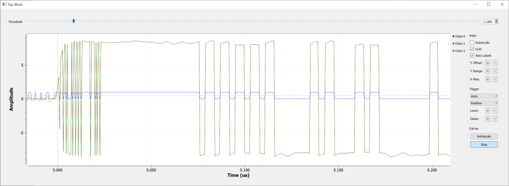
Although the on-air data is clearly visible, the samplerate (2.4MHz) to create a usable eye pattern is just too low I'm afraid.
My setup is a cheap RTL2832U RTL-SDR dongle, with BT-281 downconverter, as described here: http://blog.cyberexplorer.me/2014/01/sniffing-and-decoding-nrf24l01-and.html , no match for your USRP B210
-
That would mean IRQ on pin 2 (pro-mini or nano)?
Could be a wire-bridge for a lot of my boards I think...
-
@boozz said in nRF24L01+ Communication Failure: Root Cause and “Solution”:
That would mean IRQ on pin 2 (pro-mini or nano)?
2 or 3, and it should work for other interrupt pins too (yet untested).
-
Ok, great! I presume it requires me to set this pin somewhere in the #define section? Could you hint me what variable is used for that in the config section? I guess the MY_RFM69_IRQ_PIN is not the proper one.
About the other interrupt pins: That's an interesting one. I only know of pin 2 and 3 being the interrupt pins on a pro-mini / nano. Is it possible to use other pins for that? If so, how to achieve that?
-
-
@mfalkvidd
Thanks!
I guessed something like that, but couldn't find it in the API section
-
I've been having range issues so I gave this approach a try. I've been testing the @odritter solution along with the @tekka improvements and while the no interrupt code is totally operative, the proposed is not. At least on my network. I'll be reviewing it as I think it may be some bug on the coding.
That's:
	do {
#ifdef MY_RF24_IRQ_PIN
		RF24_DEBUG(PSTR("RF24:TXM:IRQ_PIN_WAIT\n"));
		RF24_status = hwDigitalRead(MY_RF24_IRQ_PIN);
	} while (RF24_status && timeout--);
        // timeout value after successful TX on 16Mhz AVR ~ 65500, i.e. msg is transmitted after ~36 loop cycles
        RF24_status = RF24_getStatus();
#else
		delayMicroseconds(MINIMAL_AIR_TIME_US + len * AIR_TIME_BYTE_US);
		RF24_status = RF24_getStatus();
	} while (!(RF24_status & (_BV(RF24_MAX_RT) | _BV(RF24_TX_DS))) && timeout--);
#endif
-
This is what I get with @odritter code:
09:37:10.346 ->
09:37:10.346 ->  __  __       ____
09:37:10.346 -> |  \/  |_   _/ ___|  ___ _ __  ___  ___  _ __ ___
09:37:10.346 -> | |\/| | | | \___ \ / _ \ `_ \/ __|/ _ \| `__/ __|
09:37:10.346 -> | |  | | |_| |___| |  __/ | | \__ \  _  | |  \__ \
09:37:10.346 -> |_|  |_|\__, |____/ \___|_| |_|___/\___/|_|  |___/
09:37:10.346 ->         |___/                      2.3.1
09:37:10.346 ->
09:37:10.346 -> 16 MCO:BGN:INIT NODE,CP=RNNNA---,REL=255,VER=2.3.1
09:37:10.346 -> 26 MCO:BGN:BFR
09:37:10.346 -> 27 TSM:INIT
09:37:10.346 -> 28 TSF:WUR:MS=0
09:37:10.379 -> 35 TSM:INIT:TSP OK
09:37:10.379 -> 37 TSF:SID:OK,ID=6
09:37:10.379 -> 38 TSM:FPAR
09:37:10.379 -> 40 TSF:MSG:SEND,6-6-255-255,s=255,c=3,t=7,pt=0,l=0,sg=0,ft=0,st=OK:
09:37:12.387 -> 2048 !TSM:FPAR:NO REPLY
09:37:12.387 -> 2050 TSM:FPAR
09:37:12.387 -> 2052 TSF:MSG:SEND,6-6-255-255,s=255,c=3,t=7,pt=0,l=0,sg=0,ft=0,st=OK:
09:37:14.398 -> 4059 !TSM:FPAR:NO REPLY
09:37:14.398 -> 4061 TSM:FPAR
09:37:14.398 -> 4063 TSF:MSG:SEND,6-6-255-255,s=255,c=3,t=7,pt=0,l=0,sg=0,ft=0,st=OK:
09:37:16.417 -> 6070 !TSM:FPAR:NO REPLY
09:37:16.417 -> 6072 TSM:FPAR
09:37:16.417 -> 6074 TSF:MSG:SEND,6-6-255-255,s=255,c=3,t=7,pt=0,l=0,sg=0,ft=0,st=OK:
09:37:18.409 -> 8081 !TSM:FPAR:FAIL
09:37:18.409 -> 8082 TSM:FAIL:CNT=1
09:37:18.409 -> 8084 TSM:FAIL:DIS
09:37:18.409 -> 8086 TSF:TDI:TSL
09:37:28.413 -> 18088 TSM:FAIL:RE-INIT
...
Edit: There was no coding error, but I found that if MY_DEBUG_VERBOSE_RF24 is enabled, the code starts to work with IRQs.
And dumps:09:47:01.018 -> 09:47:01.018 -> __ __ ____ 09:47:01.018 -> | \/ |_ _/ ___| ___ _ __ ___ ___ _ __ ___ 09:47:01.018 -> | |\/| | | | \___ \ / _ \ `_ \/ __|/ _ \| `__/ __| 09:47:01.018 -> | | | | |_| |___| | __/ | | \__ \ _ | | \__ \ 09:47:01.018 -> |_| |_|\__, |____/ \___|_| |_|___/\___/|_| |___/ 09:47:01.018 -> |___/ 2.3.1 09:47:01.018 -> 09:47:01.018 -> 16 MCO:BGN:INIT NODE,CP=RNNNA---,REL=255,VER=2.3.1 09:47:01.018 -> 26 MCO:BGN:BFR 09:47:01.018 -> 27 TSM:INIT 09:47:01.018 -> 28 TSF:WUR:MS=0 09:47:01.018 -> 30 RF24:INIT:PIN,CE=9,CS=10 09:47:01.053 -> 32 RF24:SBY 09:47:01.053 -> 33 RF24:WBR:REG=0,VAL=14 09:47:01.053 -> 40 RF24:WBR:REG=3,VAL=3 09:47:01.053 -> 43 RF24:WBR:REG=4,VAL=95 09:47:01.053 -> 45 RF24:WBR:REG=5,VAL=108 09:47:01.053 -> 48 RF24:WBR:REG=6,VAL=37 09:47:01.053 -> 50 RF24:WBR:REG=29,VAL=4 09:47:01.053 -> 52 RF24:RBR:REG=29,VAL=4 09:47:01.053 -> 54 RF24:RBR:REG=6,VAL=37 09:47:01.053 -> 56 RF24:RBR:REG=5,VAL=108 09:47:01.053 -> 59 RF24:WBR:REG=2,VAL=2 09:47:01.053 -> 61 RF24:WBR:REG=1,VAL=0 09:47:01.053 -> 63 RF24:WBR:REG=28,VAL=3 09:47:01.053 -> 65 RF24:FRX 09:47:01.053 -> 66 RF24:FTX 09:47:01.088 -> 67 RF24:WBR:REG=7,VAL=112 09:47:01.088 -> 70 TSM:INIT:TSP OK 09:47:01.088 -> 71 RF24:WBR:REG=2,VAL=3 09:47:01.088 -> 73 RF24:WBR:REG=1,VAL=1 09:47:01.088 -> 76 RF24:STL 09:47:01.088 -> 77 RF24:WBR:REG=0,VAL=15 09:47:01.088 -> 79 RF24:WBR:REG=10,VAL=6 09:47:01.088 -> 81 TSF:SID:OK,ID=6 09:47:01.088 -> 83 TSM:FPAR 09:47:01.088 -> 84 RF24:SPL 09:47:01.088 -> 86 RF24:WBR:REG=0,VAL=14 09:47:01.088 -> 88 RF24:OWP:RCPT=255 09:47:01.088 -> 90 RF24:WBR:REG=10,VAL=255 09:47:01.088 -> 92 RF24:WBR:REG=16,VAL=255 09:47:01.088 -> 95 RF24:TXM:TO=255,LEN=7 09:47:01.088 -> 97 RF24:FTX 09:47:01.088 -> 98 RF24:TXM:IRQ_PIN_WAIT 09:47:01.088 -> 100 RF24:TXM:IRQ_PIN_WAIT 09:47:01.088 -> 101 RF24:TXM:IRQ_PIN_WAIT 09:47:01.123 -> 103 RF24:TXM:IRQ_PIN_WAIT 09:47:01.123 -> 105 RF24:TXM:IRQ_PIN_WAIT 09:47:01.123 -> 107 RF24:TXM:IRQ_PIN_WAIT 09:47:01.123 -> 108 RF24:TXM:IRQ_PIN_WAIT 09:47:01.123 -> 110 RF24:TXM:IRQ_PIN_WAIT 09:47:01.123 -> 112 RF24:TXM:IRQ_PIN_WAIT 09:47:01.123 -> 113 RF24:TXM:IRQ_PIN_WAIT 09:47:01.123 -> 115 RF24:TXM:IRQ_PIN_WAIT 09:47:01.123 -> 117 RF24:TXM:IRQ_PIN_WAIT 09:47:01.123 -> 118 RF24:TXM:IRQ_PIN_WAIT 09:47:01.123 -> 120 RF24:TXM:IRQ_PIN_WAIT 09:47:01.123 -> 122 RF24:TXM:IRQ_PIN_WAIT 09:47:01.123 -> 124 RF24:TXM:IRQ_PIN_WAIT 09:47:01.123 -> 125 RF24:TXM:IRQ_PIN_WAIT 09:47:01.123 -> 128 RF24:TXM:IRQ_PIN_WAIT 09:47:01.123 -> 130 RF24:TXM:IRQ_PIN_WAIT 09:47:01.123 -> 131 RF24:TXM:IRQ_PIN_WAIT 09:47:01.123 -> 133 RF24:RBR:REG=8,VAL=31 09:47:01.123 -> 135 RF24:TXM:AIR=1188,EFF=37112,OBS=15,CNT= 31 09:47:01.158 -> 140 RF24:WBR:REG=7,VAL=48 09:47:01.158 -> 142 ?RF24:TXM:MAX_RT 09:47:01.158 -> 144 RF24:FTX 09:47:01.158 -> 145 RF24:STL 09:47:01.158 -> 146 RF24:WBR:REG=0,VAL=15 09:47:01.158 -> 148 RF24:WBR:REG=10,VAL=6 09:47:01.158 -> 151 TSF:MSG:SEND,6-6-255-255,s=255,c=3,t=7,pt=0,l=0,sg=0,ft=0,st=OK: 09:47:01.610 -> 603 RF24:RXM:LEN=8 09:47:01.610 -> 605 RF24:WBR:REG=7,VAL=64 09:47:01.610 -> 607 TSF:MSG:READ,0-0-6,s=255,c=3,t=8,pt=1,l=1,sg=0:0 09:47:01.610 -> 612 TSF:MSG:FPAR OK,ID=0,D=1 09:47:03.178 -> 2158 TSM:FPAR:OK 09:47:03.178 -> 2159 TSM:ID 09:47:03.178 -> 2160 TSM:ID:OK 09:47:03.178 -> 2162 TSM:UPL 09:47:03.178 -> 2163 RF24:SPL 09:47:03.178 -> 2164 RF24:WBR:REG=0,VAL=14 09:47:03.178 -> 2167 RF24:OWP:RCPT=0 09:47:03.178 -> 2169 RF24:WBR:REG=10,VAL=0 09:47:03.178 -> 2171 RF24:WBR:REG=16,VAL=0 09:47:03.178 -> 2174 RF24:TXM:TO=0,LEN=8 09:47:03.178 -> 2177 RF24:FTX 09:47:03.178 -> 2178 RF24:TXM:IRQ_PIN_WAIT 09:47:03.178 -> 2180 RF24:RBR:REG=8,VAL=16 09:47:03.178 -> 2183 RF24:TXM:AIR=1220,EFF=4388,OBS=0,CNT= 50 09:47:03.178 -> 2187 RF24:WBR:REG=7,VAL=48 09:47:03.178 -> 2189 RF24:STL 09:47:03.178 -> 2190 RF24:WBR:REG=0,VAL=15 09:47:03.178 -> 2193 RF24:WBR:REG=10,VAL=6 09:47:03.213 -> 2195 TSF:MSG:SEND,6-6-0-0,s=255,c=3,t=24,pt=1,l=1,sg=0,ft=0,st=OK:1 09:47:03.213 -> 2201 RF24:RXM:LEN=8 09:47:03.213 -> 2203 RF24:WBR:REG=7,VAL=64 09:47:03.213 -> 2206 TSF:MSG:READ,0-0-6,s=255,c=3,t=25,pt=1,l=1,sg=0:1 09:47:03.213 -> 2211 TSF:MSG:PONG RECV,HP=1 09:47:03.213 -> 2213 TSM:UPL:OK 09:47:03.213 -> 2215 TSM:READY:ID=6,PAR=0,DIS=1 09:47:03.213 -> 2219 RF24:SPL 09:47:03.213 -> 2220 RF24:WBR:REG=0,VAL=14 09:47:03.213 -> 2223 RF24:OWP:RCPT=0 09:47:03.213 -> 2224 RF24:WBR:REG=10,VAL=0 09:47:03.213 -> 2227 RF24:WBR:REG=16,VAL=0 09:47:03.248 -> 2229 RF24:TXM:TO=0,LEN=9 09:47:03.248 -> 2232 RF24:FTX 09:47:03.248 -> 2233 RF24:TXM:IRQ_PIN_WAIT 09:47:03.248 -> 2235 RF24:RBR:REG=8,VAL=16 09:47:03.248 -> 2237 RF24:TXM:AIR=1252,EFF=4380,OBS=0,CNT= 50 09:47:03.248 -> 2241 RF24:WBR:REG=7,VAL=48 09:47:03.248 -> 2244 RF24:STL 09:47:03.248 -> 2245 RF24:WBR:REG=0,VAL=15 09:47:03.248 -> 2247 RF24:WBR:REG=10,VAL=6 09:47:03.248 -> 2250 TSF:MSG:SEND,6-6-0-0,s=255,c=3,t=15,pt=6,l=2,sg=0,ft=0,st=OK:0100 09:47:03.248 -> 2256 RF24:RXM:LEN=9 09:47:03.248 -> 2258 RF24:WBR:REG=7,VAL=64 09:47:03.248 -> 2262 TSF:MSG:READ,0-0-6,s=255,c=3,t=15,pt=6,l=2,sg=0:0100 09:47:03.283 -> 2267 RF24:SPL 09:47:03.283 -> 2268 RF24:WBR:REG=0,VAL=14 09:47:03.283 -> 2271 RF24:OWP:RCPT=0 09:47:03.283 -> 2273 RF24:WBR:REG=10,VAL=0 09:47:03.283 -> 2275 RF24:WBR:REG=16,VAL=0 09:47:03.283 -> 2278 RF24:TXM:TO=0,LEN=12 09:47:03.283 -> 2280 RF24:FTX 09:47:03.283 -> 2281 RF24:TXM:IRQ_PIN_WAIT 09:47:03.283 -> 2283 RF24:RBR:REG=8,VAL=16 09:47:03.283 -> 2286 RF24:TXM:AIR=1348,EFF=4388,OBS=0,CNT= 50 09:47:03.283 -> 2290 RF24:WBR:REG=7,VAL=48 09:47:03.283 -> 2292 RF24:STL 09:47:03.283 -> 2293 RF24:WBR:REG=0,VAL=15 09:47:03.283 -> 2296 RF24:WBR:REG=10,VAL=6 09:47:03.317 -> 2298 TSF:MSG:SEND,6-6-0-0,s=255,c=0,t=17,pt=0,l=5,sg=0,ft=0,st=OK:2.3.1 09:47:03.317 -> 2306 RF24:SPL 09:47:03.317 -> 2307 RF24:WBR:REG=0,VAL=14 09:47:03.317 -> 2310 RF24:OWP:RCPT=0 09:47:03.317 -> 2312 RF24:WBR:REG=10,VAL=0 09:47:03.317 -> 2314 RF24:WBR:REG=16,VAL=0 09:47:03.317 -> 2317 RF24:TXM:TO=0,LEN=8 09:47:03.317 -> 2319 RF24:FTX 09:47:03.317 -> 2320 RF24:TXM:IRQ_PIN_WAIT 09:47:03.317 -> 2322 RF24:RBR:REG=8,VAL=16 09:47:03.317 -> 2324 RF24:TXM:AIR=1220,EFF=4380,OBS=0,CNT= 50 09:47:03.317 -> 2328 RF24:WBR:REG=7,VAL=48 09:47:03.352 -> 2331 RF24:STL 09:47:03.352 -> 2332 RF24:WBR:REG=0,VAL=15 09:47:03.352 -> 2335 RF24:WBR:REG=10,VAL=6 09:47:03.352 -> 2337 TSF:MSG:SEND,6-6-0-0,s=255,c=3,t=6,pt=1,l=1,sg=0,ft=0,st=OK:0 09:47:03.352 -> 2343 RF24:RXM:LEN=8 09:47:03.352 -> 2345 RF24:WBR:REG=7,VAL=64 09:47:03.352 -> 2348 TSF:MSG:READ,0-0-6,s=255,c=3,t=6,pt=0,l=1,sg=0:M 09:47:03.352 -> 2353 RF24:RXM:LEN=8 09:47:03.352 -> 2355 RF24:WBR:REG=7,VAL=64 09:47:03.352 -> 2358 TSF:MSG:READ,0-0-6,s=255,c=3,t=6,pt=0,l=1,sg=0:M 09:47:03.352 -> 2363 RF24:SPL 09:47:03.352 -> 2364 RF24:WBR:REG=0,VAL=14 09:47:03.352 -> 2367 RF24:OWP:RCPT=0 09:47:03.387 -> 2368 RF24:WBR:REG=10,VAL=0 09:47:03.387 -> 2371 RF24:WBR:REG=16,VAL=0 09:47:03.387 -> 2373 RF24:TXM:TO=0,LEN=26 09:47:03.387 -> 2376 RF24:FTX 09:47:03.387 -> 2377 RF24:TXM:IRQ_PIN_WAIT 09:47:03.387 -> 2379 RF24:RBR:REG=8,VAL=16 09:47:03.387 -> 2381 RF24:TXM:AIR=1796,EFF=4384,OBS=0,CNT= 50 09:47:03.387 -> 2385 RF24:WBR:REG=7,VAL=48 09:47:03.387 -> 2388 RF24:STL 09:47:03.387 -> 2390 RF24:WBR:REG=0,VAL=15 09:47:03.387 -> 2393 RF24:WBR:REG=10,VAL=6 09:47:03.387 -> 2395 TSF:MSG:SEND,6-6-0-0,s=255,c=3,t=11,pt=0,l=19,sg=0,ft=0,st=OK:MySimple_MultiRelay 09:47:03.422 -> 2403 RF24:SPL 09:47:03.422 -> 2404 RF24:WBR:REG=0,VAL=14 09:47:03.422 -> 2407 RF24:OWP:RCPT=0 09:47:03.422 -> 2409 RF24:WBR:REG=10,VAL=0 09:47:03.422 -> 2411 RF24:WBR:REG=16,VAL=0 09:47:03.422 -> 2414 RF24:TXM:TO=0,LEN=10 09:47:03.422 -> 2416 RF24:FTX 09:47:03.422 -> 2417 RF24:TXM:IRQ_PIN_WAIT 09:47:03.422 -> 2419 RF24:RBR:REG=8,VAL=16 09:47:03.422 -> 2422 RF24:TXM:AIR=1284,EFF=4380,OBS=0,CNT= 50 09:47:03.422 -> 2426 RF24:WBR:REG=7,VAL=48 09:47:03.422 -> 2428 RF24:STL 09:47:03.422 -> 2429 RF24:WBR:REG=0,VAL=15 09:47:03.422 -> 2433 RF24:WBR:REG=10,VAL=6 09:47:03.422 -> 2435 TSF:MSG:SEND,6-6-0-0,s=255,c=3,t=12,pt=0,l=3,sg=0,ft=0,st=OK:1.2 09:47:03.456 -> 2442 RF24:SPL 09:47:03.456 -> 2443 RF24:WBR:REG=0,VAL=14 09:47:03.456 -> 2446 RF24:OWP:RCPT=0 09:47:03.456 -> 2447 RF24:WBR:REG=10,VAL=0 09:47:03.456 -> 2450 RF24:WBR:REG=16,VAL=0 09:47:03.456 -> 2452 RF24:TXM:TO=0,LEN=13 09:47:03.456 -> 2455 RF24:FTX 09:47:03.456 -> 2456 RF24:TXM:IRQ_PIN_WAIT 09:47:03.456 -> 2458 RF24:RBR:REG=8,VAL=16 09:47:03.456 -> 2460 RF24:TXM:AIR=1380,EFF=4380,OBS=0,CNT= 50 09:47:03.456 -> 2464 RF24:WBR:REG=7,VAL=48 09:47:03.456 -> 2467 RF24:STL 09:47:03.456 -> 2468 RF24:WBR:REG=0,VAL=15 09:47:03.456 -> 2471 RF24:WBR:REG=10,VAL=6 09:47:03.491 -> 2473 TSF:MSG:SEND,6-6-0-0,s=0,c=0,t=3,pt=0,l=6,sg=0,ft=0,st=OK:Zone 1 09:47:03.526 -> 2530 RF24:SPL 09:47:03.526 -> 2531 RF24:WBR:REG=0,VAL=14 09:47:03.526 -> 2534 RF24:OWP:RCPT=0 09:47:03.526 -> 2535 RF24:WBR:REG=10,VAL=0 09:47:03.526 -> 2538 RF24:WBR:REG=16,VAL=0 09:47:03.526 -> 2540 RF24:TXM:TO=0,LEN=7 09:47:03.561 -> 2543 RF24:FTX 09:47:03.561 -> 2544 RF24:TXM:IRQ_PIN_WAIT 09:47:03.561 -> 2546 RF24:RBR:REG=8,VAL=16 09:47:03.561 -> 2548 RF24:TXM:AIR=1188,EFF=4380,OBS=0,CNT= 50 09:47:03.561 -> 2552 RF24:WBR:REG=7,VAL=48 09:47:03.561 -> 2555 RF24:STL 09:47:03.561 -> 2556 RF24:WBR:REG=0,VAL=15 09:47:03.561 -> 2558 RF24:WBR:REG=10,VAL=6 09:47:03.561 -> 2562 TSF:MSG:SEND,6-6-0-0,s=0,c=0,t=24,pt=0,l=0,sg=0,ft=0,st=OK: 09:47:03.631 -> 2618 !MCO:SND:NODE NOT REG 09:47:03.666 -> 2670 RF24:SPL 09:47:03.666 -> 2671 RF24:WBR:REG=0,VAL=14 09:47:03.666 -> 2674 RF24:OWP:RCPT=0 09:47:03.666 -> 2675 RF24:WBR:REG=10,VAL=0 09:47:03.666 -> 2678 RF24:WBR:REG=16,VAL=0 09:47:03.666 -> 2680 RF24:TXM:TO=0,LEN=7 09:47:03.701 -> 2683 RF24:FTX 09:47:03.701 -> 2684 RF24:TXM:IRQ_PIN_WAIT 09:47:03.701 -> 2686 RF24:RBR:REG=8,VAL=16 09:47:03.701 -> 2689 RF24:TXM:AIR=1188,EFF=4384,OBS=0,CNT= 50 09:47:03.701 -> 2693 RF24:WBR:REG=7,VAL=48 09:47:03.701 -> 2696 RF24:STL 09:47:03.701 -> 2697 RF24:WBR:REG=0,VAL=15 09:47:03.701 -> 2699 RF24:WBR:REG=10,VAL=6 09:47:03.701 -> 2702 TSF:MSG:SEND,6-6-0-0,s=0,c=2,t=2,pt=0,l=0,sg=0,ft=0,st=OK: 09:47:03.701 -> 2708 RF24:RXM:LEN=8 09:47:03.701 -> 2710 RF24:WBR:REG=7,VAL=64 09:47:03.701 -> 2712 TSF:MSG:READ,0-0-6,s=0,c=2,t=2,pt=0,l=1,sg=0:0 09:47:03.771 -> 2758 RF24:SPL 09:47:03.771 -> 2759 RF24:WBR:REG=0,VAL=14 09:47:03.771 -> 2762 RF24:OWP:RCPT=0 09:47:03.771 -> 2763 RF24:WBR:REG=10,VAL=0 09:47:03.771 -> 2766 RF24:WBR:REG=16,VAL=0 09:47:03.771 -> 2768 RF24:TXM:TO=0,LEN=13 09:47:03.771 -> 2771 RF24:FTX 09:47:03.771 -> 2772 RF24:TXM:IRQ_PIN_WAIT 09:47:03.771 -> 2775 RF24:RBR:REG=8,VAL=16 09:47:03.771 -> 2777 RF24:TXM:AIR=1380,EFF=4384,OBS=0,CNT= 50 09:47:03.771 -> 2781 RF24:WBR:REG=7,VAL=48 09:47:03.771 -> 2784 RF24:STL 09:47:03.805 -> 2785 RF24:WBR:REG=0,VAL=15 09:47:03.805 -> 2788 RF24:WBR:REG=10,VAL=6 09:47:03.805 -> 2790 TSF:MSG:SEND,6-6-0-0,s=1,c=0,t=3,pt=0,l=6,sg=0,ft=0,st=OK:Zone 2 09:47:03.839 -> 2846 RF24:SPL 09:47:03.839 -> 2847 RF24:WBR:REG=0,VAL=14 09:47:03.839 -> 2850 RF24:OWP:RCPT=0 09:47:03.839 -> 2851 RF24:WBR:REG=10,VAL=0 09:47:03.839 -> 2854 RF24:WBR:REG=16,VAL=0 09:47:03.874 -> 2856 RF24:TXM:TO=0,LEN=7 09:47:03.874 -> 2860 RF24:FTX 09:47:03.874 -> 2861 RF24:TXM:IRQ_PIN_WAIT 09:47:03.874 -> 2863 RF24:RBR:REG=8,VAL=16 09:47:03.874 -> 2865 RF24:TXM:AIR=1188,EFF=4380,OBS=0,CNT= 50 09:47:03.874 -> 2869 RF24:WBR:REG=7,VAL=48 09:47:03.874 -> 2872 RF24:STL 09:47:03.874 -> 2873 RF24:WBR:REG=0,VAL=15 09:47:03.874 -> 2875 RF24:WBR:REG=10,VAL=6 09:47:03.874 -> 2878 TSF:MSG:SEND,6-6-0-0,s=1,c=0,t=24,pt=0,l=0,sg=0,ft=0,st=OK: 09:47:03.944 -> 2934 !MCO:SND:NODE NOT REG 09:47:03.979 -> 2987 RF24:SPL 09:47:03.979 -> 2988 RF24:WBR:REG=0,VAL=14 09:47:03.979 -> 2991 RF24:OWP:RCPT=0 09:47:03.979 -> 2992 RF24:WBR:REG=10,VAL=0 09:47:03.979 -> 2995 RF24:WBR:REG=16,VAL=0 09:47:04.013 -> 2997 RF24:TXM:TO=0,LEN=7 09:47:04.013 -> 3000 RF24:FTX 09:47:04.013 -> 3001 RF24:TXM:IRQ_PIN_WAIT 09:47:04.013 -> 3003 RF24:RBR:REG=8,VAL=16 09:47:04.013 -> 3005 RF24:TXM:AIR=1188,EFF=4380,OBS=0,CNT= 50 09:47:04.013 -> 3009 RF24:WBR:REG=7,VAL=48 09:47:04.013 -> 3012 RF24:STL 09:47:04.013 -> 3013 RF24:WBR:REG=0,VAL=15 09:47:04.013 -> 3015 RF24:WBR:REG=10,VAL=6 09:47:04.013 -> 3018 TSF:MSG:SEND,6-6-0-0,s=1,c=2,t=2,pt=0,l=0,sg=0,ft=0,st=OK: 09:47:04.013 -> 3024 RF24:RXM:LEN=8 09:47:04.013 -> 3026 RF24:WBR:REG=7,VAL=64 09:47:04.047 -> 3028 TSF:MSG:READ,0-0-6,s=1,c=2,t=2,pt=0,l=1,sg=0:0 09:47:04.081 -> 3074 RF24:SPL 09:47:04.081 -> 3075 RF24:WBR:REG=0,VAL=14 09:47:04.081 -> 3078 RF24:OWP:RCPT=0 09:47:04.081 -> 3079 RF24:WBR:REG=10,VAL=0 09:47:04.081 -> 3082 RF24:WBR:REG=16,VAL=0 09:47:04.081 -> 3084 RF24:TXM:TO=0,LEN=13 09:47:04.081 -> 3087 RF24:FTX 09:47:04.081 -> 3088 RF24:TXM:IRQ_PIN_WAIT 09:47:04.081 -> 3090 RF24:RBR:REG=8,VAL=16 09:47:04.081 -> 3092 RF24:TXM:AIR=1380,EFF=4384,OBS=0,CNT= 50 09:47:04.081 -> 3096 RF24:WBR:REG=7,VAL=48 09:47:04.115 -> 3099 RF24:STL 09:47:04.115 -> 3100 RF24:WBR:REG=0,VAL=15 09:47:04.115 -> 3103 RF24:WBR:REG=10,VAL=6 09:47:04.115 -> 3105 TSF:MSG:SEND,6-6-0-0,s=2,c=0,t=3,pt=0,l=6,sg=0,ft=0,st=OK:Zone 3 09:47:04.149 -> 3161 RF24:SPL 09:47:04.149 -> 3162 RF24:WBR:REG=0,VAL=14 09:47:04.182 -> 3165 RF24:OWP:RCPT=0 09:47:04.182 -> 3166 RF24:WBR:REG=10,VAL=0 09:47:04.182 -> 3169 RF24:WBR:REG=16,VAL=0 09:47:04.182 -> 3171 RF24:TXM:TO=0,LEN=7 09:47:04.182 -> 3174 RF24:FTX 09:47:04.182 -> 3175 RF24:TXM:IRQ_PIN_WAIT 09:47:04.182 -> 3177 RF24:RBR:REG=8,VAL=16 09:47:04.182 -> 3179 RF24:TXM:AIR=1188,EFF=4384,OBS=0,CNT= 50 09:47:04.182 -> 3183 RF24:WBR:REG=7,VAL=48 09:47:04.182 -> 3186 RF24:STL 09:47:04.182 -> 3187 RF24:WBR:REG=0,VAL=15 09:47:04.182 -> 3189 RF24:WBR:REG=10,VAL=6 09:47:04.182 -> 3192 TSF:MSG:SEND,6-6-0-0,s=2,c=0,t=24,pt=0,l=0,sg=0,ft=0,st=OK: 09:47:04.250 -> 3248 !MCO:SND:NODE NOT REG 09:47:04.319 -> 3300 RF24:SPL 09:47:04.319 -> 3301 RF24:WBR:REG=0,VAL=14 09:47:04.319 -> 3304 RF24:OWP:RCPT=0 09:47:04.319 -> 3305 RF24:WBR:REG=10,VAL=0 09:47:04.319 -> 3308 RF24:WBR:REG=16,VAL=0 09:47:04.319 -> 3310 RF24:TXM:TO=0,LEN=7 09:47:04.319 -> 3313 RF24:FTX 09:47:04.319 -> 3314 RF24:TXM:IRQ_PIN_WAIT 09:47:04.319 -> 3316 RF24:RBR:REG=8,VAL=16 09:47:04.319 -> 3318 RF24:TXM:AIR=1188,EFF=4380,OBS=0,CNT= 50 09:47:04.319 -> 3322 RF24:WBR:REG=7,VAL=48 09:47:04.319 -> 3325 RF24:STL 09:47:04.319 -> 3326 RF24:WBR:REG=0,VAL=15 09:47:04.319 -> 3329 RF24:WBR:REG=10,VAL=6 09:47:04.319 -> 3332 TSF:MSG:SEND,6-6-0-0,s=2,c=2,t=2,pt=0,l=0,sg=0,ft=0,st=OK: 09:47:04.353 -> 3338 RF24:RXM:LEN=8 09:47:04.353 -> 3340 RF24:WBR:REG=7,VAL=64 09:47:04.353 -> 3342 TSF:MSG:READ,0-0-6,s=2,c=2,t=2,pt=0,l=1,sg=0:0 09:47:04.387 -> 3388 RF24:SPL 09:47:04.387 -> 3389 RF24:WBR:REG=0,VAL=14 09:47:04.387 -> 3392 RF24:OWP:RCPT=0 09:47:04.387 -> 3393 RF24:WBR:REG=10,VAL=0 09:47:04.387 -> 3396 RF24:WBR:REG=16,VAL=0 09:47:04.387 -> 3398 RF24:TXM:TO=0,LEN=13 09:47:04.387 -> 3401 RF24:FTX 09:47:04.387 -> 3402 RF24:TXM:IRQ_PIN_WAIT 09:47:04.421 -> 3404 RF24:RBR:REG=8,VAL=16 09:47:04.421 -> 3406 RF24:TXM:AIR=1380,EFF=4380,OBS=0,CNT= 50 09:47:04.421 -> 3410 RF24:WBR:REG=7,VAL=48 09:47:04.421 -> 3414 RF24:STL 09:47:04.421 -> 3415 RF24:WBR:REG=0,VAL=15 09:47:04.421 -> 3418 RF24:WBR:REG=10,VAL=6 09:47:04.421 -> 3420 TSF:MSG:SEND,6-6-0-0,s=3,c=0,t=3,pt=0,l=6,sg=0,ft=0,st=OK:Zone 4 09:47:04.489 -> 3476 RF24:SPL 09:47:04.489 -> 3477 RF24:WBR:REG=0,VAL=14 09:47:04.489 -> 3480 RF24:OWP:RCPT=0 09:47:04.489 -> 3481 RF24:WBR:REG=10,VAL=0 09:47:04.489 -> 3484 RF24:WBR:REG=16,VAL=0 09:47:04.489 -> 3486 RF24:TXM:TO=0,LEN=7 09:47:04.489 -> 3489 RF24:FTX 09:47:04.489 -> 3490 RF24:TXM:IRQ_PIN_WAIT 09:47:04.489 -> 3492 RF24:RBR:REG=8,VAL=16 09:47:04.489 -> 3494 RF24:TXM:AIR=1188,EFF=4384,OBS=0,CNT= 50 09:47:04.489 -> 3499 RF24:WBR:REG=7,VAL=48 09:47:04.489 -> 3502 RF24:STL 09:47:04.523 -> 3503 RF24:WBR:REG=0,VAL=15 09:47:04.523 -> 3505 RF24:WBR:REG=10,VAL=6 09:47:04.523 -> 3508 TSF:MSG:SEND,6-6-0-0,s=3,c=0,t=24,pt=0,l=0,sg=0,ft=0,st=OK: 09:47:04.556 -> 3564 !MCO:SND:NODE NOT REG 09:47:04.625 -> 3616 RF24:SPL 09:47:04.625 -> 3617 RF24:WBR:REG=0,VAL=14 09:47:04.625 -> 3620 RF24:OWP:RCPT=0 09:47:04.625 -> 3621 RF24:WBR:REG=10,VAL=0 09:47:04.625 -> 3624 RF24:WBR:REG=16,VAL=0 09:47:04.625 -> 3627 RF24:TXM:TO=0,LEN=7 09:47:04.625 -> 3630 RF24:FTX 09:47:04.625 -> 3631 RF24:TXM:IRQ_PIN_WAIT 09:47:04.625 -> 3633 RF24:RBR:REG=8,VAL=16 09:47:04.625 -> 3635 RF24:TXM:AIR=1188,EFF=4384,OBS=0,CNT= 50 09:47:04.625 -> 3639 RF24:WBR:REG=7,VAL=48 09:47:04.660 -> 3642 RF24:STL 09:47:04.660 -> 3643 RF24:WBR:REG=0,VAL=15 09:47:04.660 -> 3645 RF24:WBR:REG=10,VAL=6 09:47:04.660 -> 3648 TSF:MSG:SEND,6-6-0-0,s=3,c=2,t=2,pt=0,l=0,sg=0,ft=0,st=OK: 09:47:04.660 -> 3654 RF24:RXM:LEN=8 09:47:04.660 -> 3656 RF24:WBR:REG=7,VAL=64 09:47:04.660 -> 3658 TSF:MSG:READ,0-0-6,s=3,c=2,t=2,pt=0,l=1,sg=0:0 09:47:04.695 -> 3704 RF24:SPL 09:47:04.695 -> 3705 RF24:WBR:REG=0,VAL=14 09:47:04.695 -> 3708 RF24:OWP:RCPT=0 09:47:04.695 -> 3709 RF24:WBR:REG=10,VAL=0 09:47:04.730 -> 3713 RF24:WBR:REG=16,VAL=0 09:47:04.730 -> 3715 RF24:TXM:TO=0,LEN=13 09:47:04.730 -> 3718 RF24:FTX 09:47:04.730 -> 3719 RF24:TXM:IRQ_PIN_WAIT 09:47:04.730 -> 3721 RF24:RBR:REG=8,VAL=16 09:47:04.730 -> 3723 RF24:TXM:AIR=1380,EFF=4384,OBS=0,CNT= 50 09:47:04.730 -> 3727 RF24:WBR:REG=7,VAL=48 09:47:04.730 -> 3730 RF24:STL 09:47:04.730 -> 3731 RF24:WBR:REG=0,VAL=15 09:47:04.730 -> 3734 RF24:WBR:REG=10,VAL=6 09:47:04.730 -> 3736 TSF:MSG:SEND,6-6-0-0,s=4,c=0,t=3,pt=0,l=6,sg=0,ft=0,st=OK:Zone 5 09:47:04.800 -> 3792 RF24:SPL 09:47:04.800 -> 3793 RF24:WBR:REG=0,VAL=14 09:47:04.800 -> 3796 RF24:OWP:RCPT=0 09:47:04.800 -> 3798 RF24:WBR:REG=10,VAL=0 09:47:04.800 -> 3801 RF24:WBR:REG=16,VAL=0 09:47:04.800 -> 3803 RF24:TXM:TO=0,LEN=7 09:47:04.800 -> 3806 RF24:FTX 09:47:04.800 -> 3807 RF24:TXM:IRQ_PIN_WAIT 09:47:04.800 -> 3809 RF24:RBR:REG=8,VAL=16 09:47:04.800 -> 3811 RF24:TXM:AIR=1188,EFF=4384,OBS=0,CNT= 50 09:47:04.800 -> 3815 RF24:WBR:REG=7,VAL=48 09:47:04.835 -> 3818 RF24:STL 09:47:04.835 -> 3819 RF24:WBR:REG=0,VAL=15 09:47:04.835 -> 3821 RF24:WBR:REG=10,VAL=6 09:47:04.835 -> 3824 TSF:MSG:SEND,6-6-0-0,s=4,c=0,t=24,pt=0,l=0,sg=0,ft=0,st=OK: 09:47:04.869 -> 3880 !MCO:SND:NODE NOT REG 09:47:04.936 -> 3933 RF24:SPL 09:47:04.936 -> 3934 RF24:WBR:REG=0,VAL=14 09:47:04.936 -> 3937 RF24:OWP:RCPT=0 09:47:04.936 -> 3938 RF24:WBR:REG=10,VAL=0 09:47:04.936 -> 3941 RF24:WBR:REG=16,VAL=0 09:47:04.936 -> 3943 RF24:TXM:TO=0,LEN=7 09:47:04.936 -> 3946 RF24:FTX 09:47:04.936 -> 3947 RF24:TXM:IRQ_PIN_WAIT 09:47:04.936 -> 3949 RF24:RBR:REG=8,VAL=16 09:47:04.970 -> 3951 RF24:TXM:AIR=1188,EFF=4384,OBS=0,CNT= 50 09:47:04.970 -> 3955 RF24:WBR:REG=7,VAL=48 09:47:04.970 -> 3958 RF24:STL 09:47:04.970 -> 3959 RF24:WBR:REG=0,VAL=15 09:47:04.970 -> 3961 RF24:WBR:REG=10,VAL=6 09:47:04.970 -> 3964 TSF:MSG:SEND,6-6-0-0,s=4,c=2,t=2,pt=0,l=0,sg=0,ft=0,st=OK: 09:47:04.970 -> 3971 RF24:RXM:LEN=8 09:47:04.970 -> 3973 RF24:WBR:REG=7,VAL=64 09:47:04.970 -> 3975 TSF:MSG:READ,0-0-6,s=4,c=2,t=2,pt=0,l=1,sg=0:0 09:47:05.038 -> 4021 RF24:SPL 09:47:05.038 -> 4022 RF24:WBR:REG=0,VAL=14 09:47:05.038 -> 4025 RF24:OWP:RCPT=0 09:47:05.038 -> 4026 RF24:WBR:REG=10,VAL=0 09:47:05.038 -> 4029 RF24:WBR:REG=16,VAL=0 09:47:05.038 -> 4031 RF24:TXM:TO=0,LEN=13 09:47:05.038 -> 4034 RF24:FTX 09:47:05.038 -> 4035 RF24:TXM:IRQ_PIN_WAIT 09:47:05.038 -> 4037 RF24:RBR:REG=8,VAL=16 09:47:05.038 -> 4039 RF24:TXM:AIR=1380,EFF=4380,OBS=0,CNT= 50 09:47:05.038 -> 4043 RF24:WBR:REG=7,VAL=48 09:47:05.038 -> 4046 RF24:STL 09:47:05.038 -> 4047 RF24:WBR:REG=0,VAL=15 09:47:05.038 -> 4050 RF24:WBR:REG=10,VAL=6 09:47:05.038 -> 4052 TSF:MSG:SEND,6-6-0-0,s=5,c=0,t=3,pt=0,l=6,sg=0,ft=0,st=OK:Zone 6 09:47:05.106 -> 4109 RF24:SPL 09:47:05.106 -> 4110 RF24:WBR:REG=0,VAL=14 09:47:05.106 -> 4113 RF24:OWP:RCPT=0 09:47:05.106 -> 4114 RF24:WBR:REG=10,VAL=0 09:47:05.106 -> 4117 RF24:WBR:REG=16,VAL=0 09:47:05.106 -> 4119 RF24:TXM:TO=0,LEN=7 09:47:05.141 -> 4122 RF24:FTX 09:47:05.141 -> 4123 RF24:TXM:IRQ_PIN_WAIT 09:47:05.141 -> 4125 RF24:RBR:REG=8,VAL=16 09:47:05.141 -> 4127 RF24:TXM:AIR=1188,EFF=4380,OBS=0,CNT= 50 09:47:05.141 -> 4131 RF24:WBR:REG=7,VAL=48 09:47:05.141 -> 4134 RF24:STL 09:47:05.141 -> 4135 RF24:WBR:REG=0,VAL=15 09:47:05.141 -> 4137 RF24:WBR:REG=10,VAL=6 09:47:05.141 -> 4141 TSF:MSG:SEND,6-6-0-0,s=5,c=0,t=24,pt=0,l=0,sg=0,ft=0,st=OK: 09:47:05.211 -> 4197 !MCO:SND:NODE NOT REG 09:47:05.246 -> 4249 RF24:SPL 09:47:05.246 -> 4250 RF24:WBR:REG=0,VAL=14 09:47:05.246 -> 4253 RF24:OWP:RCPT=0 09:47:05.246 -> 4254 RF24:WBR:REG=10,VAL=0 09:47:05.246 -> 4257 RF24:WBR:REG=16,VAL=0 09:47:05.246 -> 4259 RF24:TXM:TO=0,LEN=7 09:47:05.281 -> 4262 RF24:FTX 09:47:05.281 -> 4263 RF24:TXM:IRQ_PIN_WAIT 09:47:05.281 -> 4265 RF24:RBR:REG=8,VAL=16 09:47:05.281 -> 4268 RF24:TXM:AIR=1188,EFF=4384,OBS=0,CNT= 50 09:47:05.281 -> 4272 RF24:WBR:REG=7,VAL=48 09:47:05.281 -> 4275 RF24:STL 09:47:05.281 -> 4276 RF24:WBR:REG=0,VAL=15 09:47:05.281 -> 4278 RF24:WBR:REG=10,VAL=6 09:47:05.281 -> 4281 TSF:MSG:SEND,6-6-0-0,s=5,c=2,t=2,pt=0,l=0,sg=0,ft=0,st=OK: 09:47:05.281 -> 4287 RF24:RXM:LEN=8 09:47:05.281 -> 4289 RF24:WBR:REG=7,VAL=64 09:47:05.281 -> 4291 TSF:MSG:READ,0-0-6,s=5,c=2,t=2,pt=0,l=1,sg=0:0 09:47:05.350 -> 4337 RF24:SPL 09:47:05.350 -> 4338 RF24:WBR:REG=0,VAL=14 09:47:05.350 -> 4341 RF24:OWP:RCPT=0 09:47:05.350 -> 4342 RF24:WBR:REG=10,VAL=0 09:47:05.350 -> 4345 RF24:WBR:REG=16,VAL=0 09:47:05.350 -> 4347 RF24:TXM:TO=0,LEN=13 09:47:05.350 -> 4350 RF24:FTX 09:47:05.350 -> 4352 RF24:TXM:IRQ_PIN_WAIT 09:47:05.350 -> 4354 RF24:RBR:REG=8,VAL=16 09:47:05.350 -> 4356 RF24:TXM:AIR=1380,EFF=4384,OBS=0,CNT= 50 09:47:05.350 -> 4360 RF24:WBR:REG=7,VAL=48 09:47:05.350 -> 4363 RF24:STL 09:47:05.350 -> 4364 RF24:WBR:REG=0,VAL=15 09:47:05.350 -> 4367 RF24:WBR:REG=10,VAL=6 09:47:05.385 -> 4369 TSF:MSG:SEND,6-6-0-0,s=6,c=0,t=3,pt=0,l=6,sg=0,ft=0,st=OK:Zone 7 09:47:05.420 -> 4425 RF24:SPL 09:47:05.420 -> 4426 RF24:WBR:REG=0,VAL=14 09:47:05.420 -> 4429 RF24:OWP:RCPT=0 09:47:05.420 -> 4430 RF24:WBR:REG=10,VAL=0 09:47:05.420 -> 4433 RF24:WBR:REG=16,VAL=0 09:47:05.420 -> 4435 RF24:TXM:TO=0,LEN=7 09:47:05.455 -> 4439 RF24:FTX 09:47:05.455 -> 4440 RF24:TXM:IRQ_PIN_WAIT 09:47:05.455 -> 4442 RF24:RBR:REG=8,VAL=16 09:47:05.455 -> 4444 RF24:TXM:AIR=1188,EFF=4384,OBS=0,CNT= 50 09:47:05.455 -> 4448 RF24:WBR:REG=7,VAL=48 09:47:05.455 -> 4451 RF24:STL 09:47:05.455 -> 4452 RF24:WBR:REG=0,VAL=15 09:47:05.455 -> 4454 RF24:WBR:REG=10,VAL=6 09:47:05.455 -> 4457 TSF:MSG:SEND,6-6-0-0,s=6,c=0,t=24,pt=0,l=0,sg=0,ft=0,st=OK: 09:47:05.525 -> 4513 !MCO:SND:NODE NOT REG 09:47:05.560 -> 4566 RF24:SPL 09:47:05.560 -> 4567 RF24:WBR:REG=0,VAL=14 09:47:05.560 -> 4570 RF24:OWP:RCPT=0 09:47:05.560 -> 4571 RF24:WBR:REG=10,VAL=0 09:47:05.560 -> 4574 RF24:WBR:REG=16,VAL=0 09:47:05.595 -> 4576 RF24:TXM:TO=0,LEN=7 09:47:05.595 -> 4579 RF24:FTX 09:47:05.595 -> 4580 RF24:TXM:IRQ_PIN_WAIT 09:47:05.595 -> 4582 RF24:RBR:REG=8,VAL=16 09:47:05.595 -> 4584 RF24:TXM:AIR=1188,EFF=4380,OBS=0,CNT= 50 09:47:05.595 -> 4588 RF24:WBR:REG=7,VAL=48 09:47:05.595 -> 4591 RF24:STL 09:47:05.595 -> 4592 RF24:WBR:REG=0,VAL=15 09:47:05.595 -> 4594 RF24:WBR:REG=10,VAL=6 09:47:05.595 -> 4597 TSF:MSG:SEND,6-6-0-0,s=6,c=2,t=2,pt=0,l=0,sg=0,ft=0,st=OK: 09:47:05.595 -> 4603 RF24:RXM:LEN=8 09:47:05.595 -> 4605 RF24:WBR:REG=7,VAL=64 09:47:05.595 -> 4608 TSF:MSG:READ,0-0-6,s=6,c=2,t=2,pt=0,l=1,sg=0:0 09:47:05.665 -> 4653 RF24:SPL 09:47:05.665 -> 4654 RF24:WBR:REG=0,VAL=14 09:47:05.665 -> 4657 RF24:OWP:RCPT=0 09:47:05.665 -> 4658 RF24:WBR:REG=10,VAL=0 09:47:05.665 -> 4661 RF24:WBR:REG=16,VAL=0 09:47:05.665 -> 4663 RF24:TXM:TO=0,LEN=13 09:47:05.665 -> 4666 RF24:FTX 09:47:05.665 -> 4667 RF24:TXM:IRQ_PIN_WAIT 09:47:05.665 -> 4669 RF24:RBR:REG=8,VAL=16 09:47:05.665 -> 4671 RF24:TXM:AIR=1380,EFF=4384,OBS=0,CNT= 50 09:47:05.665 -> 4675 RF24:WBR:REG=7,VAL=48 09:47:05.665 -> 4678 RF24:STL 09:47:05.699 -> 4679 RF24:WBR:REG=0,VAL=15 09:47:05.699 -> 4682 RF24:WBR:REG=10,VAL=6 09:47:05.699 -> 4684 TSF:MSG:SEND,6-6-0-0,s=7,c=0,t=3,pt=0,l=6,sg=0,ft=0,st=OK:Zone 8 09:47:05.734 -> 4740 RF24:SPL 09:47:05.734 -> 4741 RF24:WBR:REG=0,VAL=14 09:47:05.734 -> 4744 RF24:OWP:RCPT=0 09:47:05.734 -> 4745 RF24:WBR:REG=10,VAL=0 09:47:05.734 -> 4748 RF24:WBR:REG=16,VAL=0 09:47:05.734 -> 4750 RF24:TXM:TO=0,LEN=7 09:47:05.769 -> 4753 RF24:FTX 09:47:05.769 -> 4754 RF24:TXM:IRQ_PIN_WAIT 09:47:05.769 -> 4756 RF24:RBR:REG=8,VAL=16 09:47:05.769 -> 4758 RF24:TXM:AIR=1188,EFF=4384,OBS=0,CNT= 50 09:47:05.769 -> 4762 RF24:WBR:REG=7,VAL=48 09:47:05.769 -> 4765 RF24:STL 09:47:05.769 -> 4766 RF24:WBR:REG=0,VAL=15 09:47:05.769 -> 4768 RF24:WBR:REG=10,VAL=6 09:47:05.769 -> 4771 TSF:MSG:SEND,6-6-0-0,s=7,c=0,t=24,pt=0,l=0,sg=0,ft=0,st=OK: 09:47:05.839 -> 4827 !MCO:SND:NODE NOT REG 09:47:05.874 -> 4879 RF24:SPL 09:47:05.874 -> 4880 RF24:WBR:REG=0,VAL=14 09:47:05.874 -> 4883 RF24:OWP:RCPT=0 09:47:05.874 -> 4884 RF24:WBR:REG=10,VAL=0 09:47:05.874 -> 4887 RF24:WBR:REG=16,VAL=0 09:47:05.874 -> 4889 RF24:TXM:TO=0,LEN=7 09:47:05.909 -> 4892 RF24:FTX 09:47:05.909 -> 4893 RF24:TXM:IRQ_PIN_WAIT 09:47:05.909 -> 4895 RF24:RBR:REG=8,VAL=16 09:47:05.909 -> 4897 RF24:TXM:AIR=1188,EFF=4380,OBS=0,CNT= 50 09:47:05.909 -> 4901 RF24:WBR:REG=7,VAL=48 09:47:05.909 -> 4904 RF24:STL 09:47:05.909 -> 4905 RF24:WBR:REG=0,VAL=15 09:47:05.909 -> 4908 RF24:WBR:REG=10,VAL=6 09:47:05.909 -> 4911 TSF:MSG:SEND,6-6-0-0,s=7,c=2,t=2,pt=0,l=0,sg=0,ft=0,st=OK: 09:47:05.909 -> 4917 RF24:RXM:LEN=8 09:47:05.909 -> 4919 RF24:WBR:REG=7,VAL=64 09:47:05.909 -> 4921 TSF:MSG:READ,0-0-6,s=7,c=2,t=2,pt=0,l=1,sg=0:0 09:47:05.979 -> 4967 MCO:REG:REQ 09:47:05.979 -> 4968 RF24:SPL 09:47:05.979 -> 4970 RF24:WBR:REG=0,VAL=14 09:47:05.979 -> 4972 RF24:OWP:RCPT=0 09:47:05.979 -> 4974 RF24:WBR:REG=10,VAL=0 09:47:05.979 -> 4976 RF24:WBR:REG=16,VAL=0 09:47:05.979 -> 4979 RF24:TXM:TO=0,LEN=8 09:47:05.979 -> 4981 RF24:FTX 09:47:05.979 -> 4983 RF24:TXM:IRQ_PIN_WAIT 09:47:05.979 -> 4984 RF24:RBR:REG=8,VAL=16 09:47:05.979 -> 4987 RF24:TXM:AIR=1220,EFF=4388,OBS=0,CNT= 50 09:47:05.979 -> 4992 RF24:WBR:REG=7,VAL=48 09:47:06.014 -> 4994 RF24:STL 09:47:06.014 -> 4996 RF24:WBR:REG=0,VAL=15 09:47:06.014 -> 4998 RF24:WBR:REG=10,VAL=6 09:47:06.014 -> 5000 TSF:MSG:SEND,6-6-0-0,s=255,c=3,t=26,pt=1,l=1,sg=0,ft=0,st=OK:2 09:47:06.014 -> 5007 RF24:RXM:LEN=8 09:47:06.014 -> 5009 RF24:WBR:REG=7,VAL=64 09:47:06.014 -> 5011 TSF:MSG:READ,0-0-6,s=255,c=3,t=27,pt=1,l=1,sg=0:1 09:47:06.014 -> 5016 MCO:PIM:NODE REG=1 09:47:06.014 -> 5018 MCO:BGN:STP 09:47:06.014 -> 5020 RF24:RBR:REG=6,VAL=37 09:47:06.014 -> 5022 RF24:RBR:REG=5,VAL=108 09:47:06.014 -> 5025 MCO:BGN:INIT OK,TSP=1This is a Multi-relay sketch.
So it seems that (for me) the OP alterations makes https://github.com/mysensors/MySensors/issues/941 bug more patent. @Yveaux @alowhum
-
@sergio-rius What are your #defines for your sensor and gateway top level? Are you using a hardware interrupt pin or a general IO?
-
@odritter The gateway is an esp8622 with my personal touch for the wifi management. Other than that the standard sketch from the site. Running the plain MyS v2.3.1
But in relation to the issue I referred, yes, should be a fast gw for it.#define MY_RADIO_RF24 #define MY_RF24_CHANNEL 108 #define MY_GATEWAY_ESP8266The node is a normal Arduino nano, bare driving an 8 relay board. The sketch is more complicated, as I developed a library that allows "discovering" the relays with minimal configuration independent of the number of them. But it doesn't trigger until the setup and the node it's failing before.
The relevant parts://///// Mysensors options ///// // Radio #define MY_RADIO_RF24 #define MY_RF24_IRQ_PIN 2 #define MY_RF24_CHANNEL 108 #define MY_DEBUG #define MY_DEBUG_VERBOSE_RF24 #include <MySensors.h>As you can see I'm using a hw interrupt, and also MyS v.2.3.1 BUT using the Tekka RF24.cpp file with the changes above to include your "waiting for interrupt". Nothing too complicated.
What I don't understand is that supposedly, the problem in the github issue appears when a node is slower than the gw, and is not still ready when the gateway answers the registration request. But your changes should make the node switch to listening faster. And then if I remove the define for irq on the node the "else" part works as expected, and also if I use IRQ on the standard v2.3.1 it works.
PS. Is that the answer from the GW doesn't have an acknowledge that a slower node can make it fail? Doesn't make sense to me. I confess that I still haven't had any time to look at it.
-
@sergio-rius said in nRF24L01+ Communication Failure: Root Cause and “Solution”:
#define MY_RF24_CHANNEL 108
Your range issues could be caused by this high channel number; clones perform worse in my experience at high channel numbers. Did you try with lower channels? (less than 90)
-
@yveaux said in nRF24L01+ Communication Failure: Root Cause and “Solution”:
@sergio-rius said in nRF24L01+ Communication Failure: Root Cause and “Solution”:
#define MY_RF24_CHANNEL 108
Your range issues could be caused by this high channel number; clones perform worse in my experience at high channel numbers. Did you try with lower channels? (less than 90)
Yes. That was the lower channel that allowed communication. Perhaps in laboratory conditions would be true, but not in reality.
I don't think it has anything to do with failing yo pair, as it works if debug is activated. Also Tekka Code works.
It's not my intention to be rude. It's only that I had plenty of developments planned that were all thrown in the box as this is not taking off. I will try with nrf5 and if it doesn't work I'll ditch it all completely. Sorry.

-
@sergio-rius My remark on the high channel number was just to address your issue with range -- I understand it doesn't influence timing between nodes and gateway.
I've read over all your posts and have a hard time understanding where you are right now.
E.g. in your last post "as it works if debug is activated. Also Tekka Code works." That suggests there is a working solution for you, with tekka's patch and debug disabled. Is this correct?To be able to help, could you briefly and clearly state what your exact issue is, what works and what doesn't. Preferably in a new thread, as this one seems to be derailing.
-
@yveaux said in nRF24L01+ Communication Failure: Root Cause and “Solution”:
E.g. in your last post "as it works if debug is activated. Also Tekka Code works." That suggests there is a working solution for you, with tekka's patch and debug disabled. Is this correct?
Yes @yveaux with my posts on this thread I was only hoping to help testing this situation, as I found interesting to also add control to TX sequences. But to my surprise the issue #941 appeared on a node (in my desk 0.5m away from gw) that never showed it before and I thought it could help with that one, as still wasn't solved. I thought I found a clue to prove that it has to do with node radio processing speed (alas SW, not HW). I don't know how pairing is synced between nodes and gw. It makes sense to me for the gw to wait and adapt to a new incoming node should already be implemented, so this issue has no logic to me.
It's true that my range it's very poor. I only have two sensors operative, and the two are in clear line of sight to the gw. The garage door controller was giving so many problems that had to deactivate it (only one floor between and just under gw) and the strips controllers work one day of ten. But it has passed some time and I should do testing again.
PS: As for at where I was with my installation (I had two operations on my hands and a baby, so I've been disconnected) my problems are nodes that appear comms dead after putting them in place and starting. Not completing the registering sequence. Others working as expected and after a while being totally disconnected from the network and at the same situation above. Randomly registering after leaving them alone for days. So two kinds of nodes, ones that finally register on their own and others never, even being so much near to the gw (4mt)
I don't find it to be a range or radio issue. It smells to me to be a network management problem.