Help with bar project....
-
Hope I can explain this so it's understandable..
I am considering purchase of a bar beverage dispenser. With this unit I would like to have the option of using the push button choice panel, (original design) or a remote system which has 6 channels (one for each beverage choice).
This remote unit will need a 6 choice selection possibility and is connected by a RF or a wireless system. The bar (pump) system is 12v and the connecting cable to the origional choice selector appears to be to a Cat6 cable.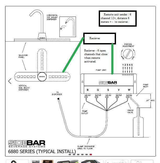
Appreciate any help
Paul
-
Hello
(brainstorming)
If you have the "original choice selector" you can tap to each wire and see what happens over individual wires when you press each button. An then simulate this from MCU (like arduino).
Or open the "original choice selector" and connect wires to the existing buttons. (That will probably void warranty.) That wires then you can connect to some MCU and "push" the buttons programmatically.
Tomas
@tssk
Thanks for the reply... Understand the warranty will be toast when I get started :-) My Idea is to use an existing joystick with left/right/forward/back + 2 separate button switches as the triggers for a remote sender that would send signals to the receiver. The wiring to the the original panel would have to be spliced on both sides of the choice button so that with activating the remote joystick would complete the connection and activate the chosen beverage to pour. This would keep (I hope) both controls usable. Google'ing "arduino" as I write.... A 12v unit (with 6 channels) that would be open until activated is what I think I need but no idea what or where I can track these down at... Any ideas?Appreciate the reply
-
Is there any connector with which the "original choice selector" is connected to the pump unit? Maybe you could create some extension without cutting the original cable.
-
Joystick seems like a strange controller to me. What is the whole idea you want to achieve with this system?
-
Most of the Arduinos can be powered with 12V.
-
If attaching to the buttons you could use relays to close the circuit and simulate the button press.
-
Do you plan to keep the "original choice selector" or replace it ?
-
-
-
Is there any connector with which the "original choice selector" is connected to the pump unit? Maybe you could create some extension without cutting the original cable.
-
Joystick seems like a strange controller to me. What is the whole idea you want to achieve with this system?
-
Most of the Arduinos can be powered with 12V.
-
If attaching to the buttons you could use relays to close the circuit and simulate the button press.
-
Do you plan to keep the "original choice selector" or replace it ?
@tssk
I haven't purchased the unit yet so I'm working with the photo's and the description in the sales info. Good point about avoiding cutting the cable - ie extension.... The cable from the selector apears to be a CAT5 or 6 cable so that makes plugging in to the system without cutting simple.
Reason for the joystick is that I have been a offshore crane operator in the north sea for the better part of my working career. My last trip out involved a issue with a button on the left joystick. The El dept onboard simple changed out the stick with a new one. The one with the button issue is here with me and this is why the joystick choice. Have been schooling myself on relays SPST/SPDT and see that this will be the way to go I think too. Is this a unit Link that I could use maybe by removing the buttons on the sender- wiring the switches to the activating switches on the joystick. Thus the joystick would replace pushing the button on the sender? -
-
According to the following picture there seems to be RJ45 connector.
So you could create RJ45 socket -> RJ45 connector cable to get in the middle without cutting anything. From there you could easily measure whats happening on the wires and maybe then simulate this with MCU.
-
Thanks for the replys... Thought it was Cat but Rj45 is probably right. That saves cable cutting... Do you think this is usable with my project 4 channel REMOTE CONTROLLER USING 4 RELAY
-
I am not sure the relay will work you need to test that first.
But if yes then I think it should work in the "Momentary" mode. But:
- you probably need 6 relays
- this is infrared so you will need line of sight with the controller
- and this module runs on 5V not 12V
-
Hello again, I'm not even a novice to PCB/project life but have in my younger years soldered a few small kit that had everything (ie... diodes,reducers... etc..) supplied. Pretty basic I know , :). Have found another unit that I'll throw at you for your feedback..
https://www.amazon.com/dp/B08BQXL4GX/ref=twister_B08C4ZBDPB?_encoding=UTF8&psc=1
Think this could work with a bit of re-wireing from the remote to the joystick?
-
Looks the same to me (5V, only 4 relays) except this is controlled by some app over wifi.
Honestly I am not a person that can give you 100% working solution. Only ideas. I am a beginner myself.
If I were you I would buy the dispenser, create the extension cord, measure with multi-meter what is happening over the wires when you press individual buttons and try to simulate this. I think if you manage to simulate it manually then you will be able to build some more sophisticated remote control. (The last module you linked would be cool that you could dispense it using voice command. Like "Alexa, rum please! :)" )
And seriously what is with the joystick? :)
-
i'm to stupid for this
Hello! It looks like you're interested in this conversation, but you don't have an account yet.
Getting fed up of having to scroll through the same posts each visit? When you register for an account, you'll always come back to exactly where you were before, and choose to be notified of new replies (either via email, or push notification). You'll also be able to save bookmarks and upvote posts to show your appreciation to other community members.
With your input, this post could be even better 💗
Register Login