Bootloading a barebones arduino
-
This post is deleted!
-
This post is deleted!
-
This post is deleted!
-
Uploaded with Crome and copied from clipboard. -
Uploaded with Crome and copied from clipboard. -
This thread was opened to continue explore how to bootload a project that was giving me fits. The project is based on wonderful work of this thread by NeverDie. That thread explores the testing of many different radios all ridding piggy-back, one at time, on a custom barebones Arduino board using the Atmega328P chip. After building said barebones board, I am having difficulty getting the bootloader loaded on to the board. AlphaHotel has very generously offered some help in a private chat session. At this moment we have been trying to find the right driver for my 7-year-old USBasp V2.0 LC Technology programmer. Bootloaders are typically, I think, installed onto new 328 chips using the SPI interface that the USBasp, as opposed to using USBTTL converters using USART interface.
There is some back story to the help session I’ve already received from AlphaHotel. I’m not going to discuss that history except to say that we tried to install a USB driver using zadig-2.7.exe. The driver we focused on was libusb-win32 driver. I think the challenge here is to get older hardware, such as the USBasp (x32), to work on newer (x64) machines like my newish Windows 10. Our efforts on loading the libusb-win32 driver did not work.
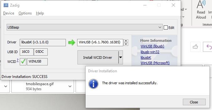
Our newer effort focused on using libusbK as a driver. I found more success with that but no success yet on the barebones bootloader install. So from here, I’ll expose our help session in the form of a thread so that we can communicate and use PIC attachments while documenting the process for others.Using the libusbK I was able to get some success bootloading. The general idea was to update the USBasp driver, then to test the new driver by bootloading then programming a Nano. If that works, then try to do the same on the barebones board. Two SW methods of bootloadings were used: 1. By using the Arduino IDE environment (Burn Bootloader) and 2. The Windows CMD (Command) application. Here is a summary of my progress with pictures of screens that display the progress.
-
Zadig driver installation of libusbK. Success!
-
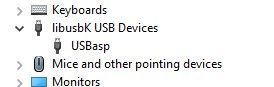
After unplugging and replugging the USBasp from the computers USB port - Device manager result:
-
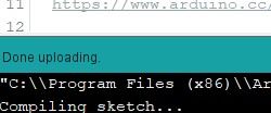
Arduino IDE Test of loading Blink to a Nano using “Upload Using Programmer” using USBasp. Success!
-
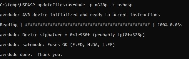
Command prompt and response with Nano Still attached:
Command: avrdude -p m328p -c usbasp
Response:
Reading | ################################################## | 100% 0.03s
avrdude: Device signature = 0x1e950f (probably lgt8fx328p)
avrdude: safemode: Fuses OK (E:FD, H:DA, L:FF)
avrdude done. Thank you.
Success!
-
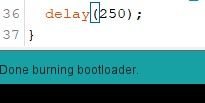
Further Arduino IDE Test of USBasp to “Burn Bootloader” to Nano
Success!
-
Fuse Settings, as shown above (E:FD, H:DA, L:FF)
Success! -
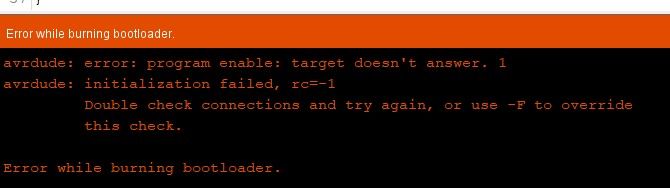
Extended test: Try to Burn Bootloader to NeverDie’s barebones board (328) using Arduino IDE. Fail.
-
Extended test: Try to burn bootloader to NeverDie’s barebonds board (328) using Avrdude. Fail.
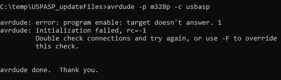
Given these last two failures on multiple tries, I’m thinking that I may have toasted the Atmega328p in the process of my soldering and bridge unsoldering. This was my first attempt for such a tiny SMD Atmega328p. I am very sure that I got the right orientation. Or, it could be that the Atmega328p that I purchased came from the bottom of somebody’s barrel.
I continue to work on this and will post results here.
-
-
For a "known good" starting point, you could pop the DIP atmega328p out of an arduino uno and practice burning your bootloader into that on a breadboard. If it gives you the same guff, then you know it's your procedure and not the chip that's at fault. Anyhow, as there's not really much that can go wrong, my WAG is that, based on @alphaHotel 's earlier comments requesting a reset-pin breakout (now baked into Version 3.0), it might have something to do with either the means or the assumptions under which your burner is accessing the reset pin.
Myself, I burn the bootloader and fuses in one of those spring-steel clamshell chip holders:
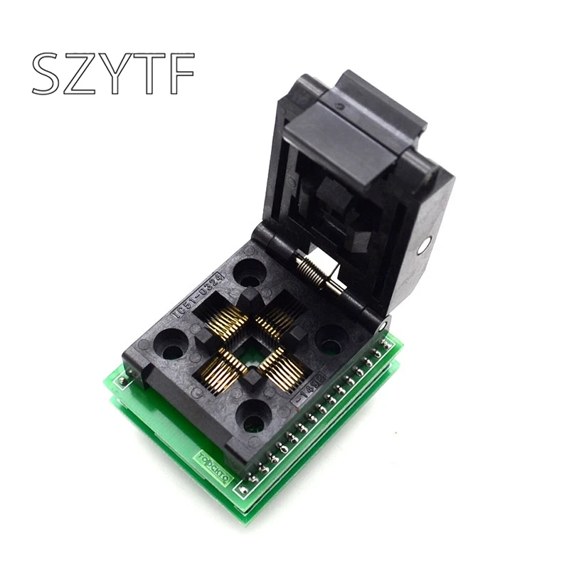
before soldering it onto the board, so I can't say that I've already done what you are attempting to do. IIRC, they cost only something like $10, but I do understand that simply knowing that doesn't really help you in the moment if you don't have one on hand already and you simply want to push forward with what you've got. -
Confirmed. Looking at the schematic of an Arduino Uno R3 and its ICSP:
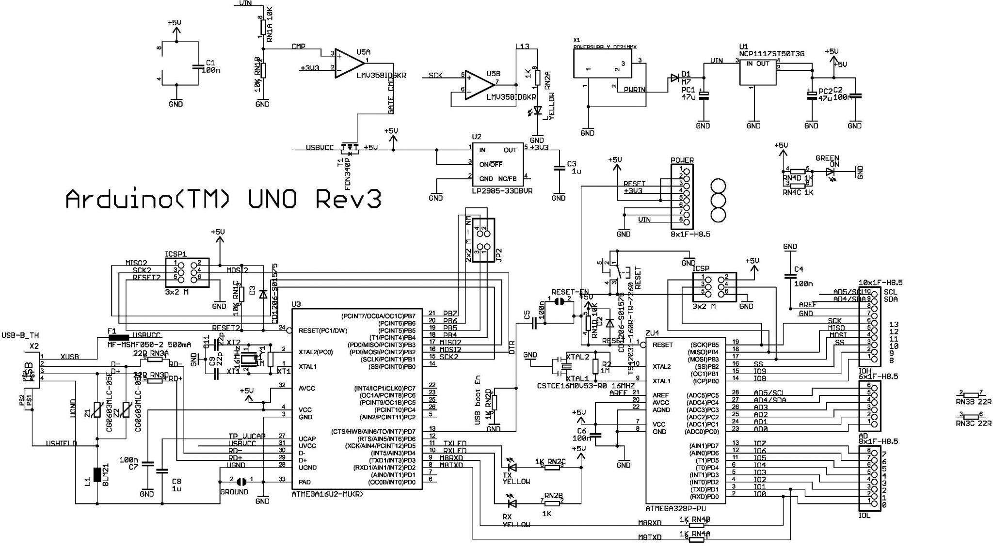
you need a direct connection to the reset pin on the chip. For that reason, you can't use the DTR pin to program it, because there's a capacitor in the way. So, that also confirms that Version 3.0 may be a worthwhile upgrade for people like you, thanks to @alphaHotel 's suggestion. -
This thread was opened to continue explore how to bootload a project that was giving me fits. The project is based on wonderful work of this thread by NeverDie. That thread explores the testing of many different radios all ridding piggy-back, one at time, on a custom barebones Arduino board using the Atmega328P chip. After building said barebones board, I am having difficulty getting the bootloader loaded on to the board. AlphaHotel has very generously offered some help in a private chat session. At this moment we have been trying to find the right driver for my 7-year-old USBasp V2.0 LC Technology programmer. Bootloaders are typically, I think, installed onto new 328 chips using the SPI interface that the USBasp, as opposed to using USBTTL converters using USART interface.
There is some back story to the help session I’ve already received from AlphaHotel. I’m not going to discuss that history except to say that we tried to install a USB driver using zadig-2.7.exe. The driver we focused on was libusb-win32 driver. I think the challenge here is to get older hardware, such as the USBasp (x32), to work on newer (x64) machines like my newish Windows 10. Our efforts on loading the libusb-win32 driver did not work.
Our newer effort focused on using libusbK as a driver. I found more success with that but no success yet on the barebones bootloader install. So from here, I’ll expose our help session in the form of a thread so that we can communicate and use PIC attachments while documenting the process for others.Using the libusbK I was able to get some success bootloading. The general idea was to update the USBasp driver, then to test the new driver by bootloading then programming a Nano. If that works, then try to do the same on the barebones board. Two SW methods of bootloadings were used: 1. By using the Arduino IDE environment (Burn Bootloader) and 2. The Windows CMD (Command) application. Here is a summary of my progress with pictures of screens that display the progress.
-
Zadig driver installation of libusbK. Success!
-
After unplugging and replugging the USBasp from the computers USB port - Device manager result:
-
Arduino IDE Test of loading Blink to a Nano using “Upload Using Programmer” using USBasp. Success!
-
Command prompt and response with Nano Still attached:
Command: avrdude -p m328p -c usbasp
Response:
Reading | ################################################## | 100% 0.03s
avrdude: Device signature = 0x1e950f (probably lgt8fx328p)
avrdude: safemode: Fuses OK (E:FD, H:DA, L:FF)
avrdude done. Thank you.
Success!
-
Further Arduino IDE Test of USBasp to “Burn Bootloader” to Nano
Success!
-
Fuse Settings, as shown above (E:FD, H:DA, L:FF)
Success! -
Extended test: Try to Burn Bootloader to NeverDie’s barebones board (328) using Arduino IDE. Fail.
-
Extended test: Try to burn bootloader to NeverDie’s barebonds board (328) using Avrdude. Fail.
Given these last two failures on multiple tries, I’m thinking that I may have toasted the Atmega328p in the process of my soldering and bridge unsoldering. This was my first attempt for such a tiny SMD Atmega328p. I am very sure that I got the right orientation. Or, it could be that the Atmega328p that I purchased came from the bottom of somebody’s barrel.
I continue to work on this and will post results here.
@Larson
I'm impressed about how much you have done here. I have a suggestion though I will readily admit to being ignorant about a lot of things.I have programed Arduino Nano's using the Arduino IDE ISP function. I had some with an old boot loader and some I just needed a touch more space. The programmed Arduino's are functioning as expected, so I don't think there's a problem.
I used this Arduino page and this youtube video to guide me how to program the Nanos. These tell you that you use another Arduino to function as the ISP and how to fashion a cable. (Judging from the discussion here, I'm sure this is not a problem for you.)
My question is, would this work to program a raw Atmega328p chip?
OSD
-
-
This thread was opened to continue explore how to bootload a project that was giving me fits. The project is based on wonderful work of this thread by NeverDie. That thread explores the testing of many different radios all ridding piggy-back, one at time, on a custom barebones Arduino board using the Atmega328P chip. After building said barebones board, I am having difficulty getting the bootloader loaded on to the board. AlphaHotel has very generously offered some help in a private chat session. At this moment we have been trying to find the right driver for my 7-year-old USBasp V2.0 LC Technology programmer. Bootloaders are typically, I think, installed onto new 328 chips using the SPI interface that the USBasp, as opposed to using USBTTL converters using USART interface.
There is some back story to the help session I’ve already received from AlphaHotel. I’m not going to discuss that history except to say that we tried to install a USB driver using zadig-2.7.exe. The driver we focused on was libusb-win32 driver. I think the challenge here is to get older hardware, such as the USBasp (x32), to work on newer (x64) machines like my newish Windows 10. Our efforts on loading the libusb-win32 driver did not work.
Our newer effort focused on using libusbK as a driver. I found more success with that but no success yet on the barebones bootloader install. So from here, I’ll expose our help session in the form of a thread so that we can communicate and use PIC attachments while documenting the process for others.Using the libusbK I was able to get some success bootloading. The general idea was to update the USBasp driver, then to test the new driver by bootloading then programming a Nano. If that works, then try to do the same on the barebones board. Two SW methods of bootloadings were used: 1. By using the Arduino IDE environment (Burn Bootloader) and 2. The Windows CMD (Command) application. Here is a summary of my progress with pictures of screens that display the progress.
-
Zadig driver installation of libusbK. Success!
-
After unplugging and replugging the USBasp from the computers USB port - Device manager result:
-
Arduino IDE Test of loading Blink to a Nano using “Upload Using Programmer” using USBasp. Success!
-
Command prompt and response with Nano Still attached:
Command: avrdude -p m328p -c usbasp
Response:
Reading | ################################################## | 100% 0.03s
avrdude: Device signature = 0x1e950f (probably lgt8fx328p)
avrdude: safemode: Fuses OK (E:FD, H:DA, L:FF)
avrdude done. Thank you.
Success!
-
Further Arduino IDE Test of USBasp to “Burn Bootloader” to Nano
Success!
-
Fuse Settings, as shown above (E:FD, H:DA, L:FF)
Success! -
Extended test: Try to Burn Bootloader to NeverDie’s barebones board (328) using Arduino IDE. Fail.
-
Extended test: Try to burn bootloader to NeverDie’s barebonds board (328) using Avrdude. Fail.
Given these last two failures on multiple tries, I’m thinking that I may have toasted the Atmega328p in the process of my soldering and bridge unsoldering. This was my first attempt for such a tiny SMD Atmega328p. I am very sure that I got the right orientation. Or, it could be that the Atmega328p that I purchased came from the bottom of somebody’s barrel.
I continue to work on this and will post results here.
Well done, forging ahead, @Larson. I wouldn't jump straight to trying to program a bootloader just yet though, we need to finish confirming communication with the chip and then if/when we get that going, look at how the fuses are set.
Looking at your post here, I believe you got these 328p's from Aliexpress (or similar). Did the listing indicate whether there was a bootloader or not? Bare chips, should be factory set to operate on the internal 8MHz oscillator, so that shouldn't be the problem. How many did you buy?
Based on your results above, at this point, it would seem that one of the following conditions exists:
- There are solder bridges (shorts) somewhere - need to test with a MM in continuity mode, each pin with all other pins. Some should be connected (GNDs for example), but most should not.
- The connections from your USBasp to the chip are incorrect. Again, you should be able to check this with a multimeter in continuity mode.
- The chip is dead. (Long live the chip.)
- The fuses are set to require an external crystal that doesn't exist. I just tested this by setting the fuses on my minimal 328P setup (see picture below). The result of which is that I now get the same error that you are getting. This is not likely the case for you but it is a possibility.
Here's a pic I just did checking continuity between the MISO contact on the USBasp and the corresponding chip pin on a minimal setup 328P for reference. Disregard that my multimeter is indicating no continuity, (my son took the picture at a bad time as I was making/breaking contact), you'll get the point of the shot though.
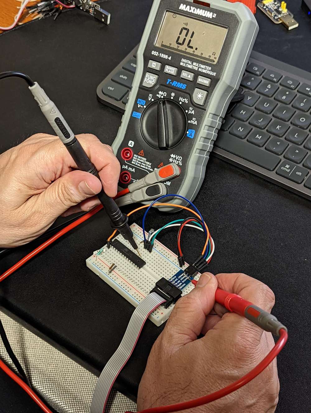
Also, take a close-up picture of the board/chip and post it here for us to see what you've got going on.
Carry on.
AH
EDIT: to add the 4th possible condition.
-
-
Confirmed. Looking at the schematic of an Arduino Uno R3 and its ICSP:
you need a direct connection to the reset pin on the chip. For that reason, you can't use the DTR pin to program it, because there's a capacitor in the way. So, that also confirms that Version 3.0 may be a worthwhile upgrade for people like you, thanks to @alphaHotel 's suggestion.@Larson I just had an idea that might help you. If you have the Version 1.0 board, then before installing the capacitor on DTR, do a solder bridge across it instead. By doing that the DTR in will be directly connected to the reset pin on your chip, and you can use the DTR pin to gain access to the reset pin on the atmega328p. When you're all done with programming the chip and then later want to switch to using an FTDI to upload your scripts, then at that point you melt the solder bridge and install the capacitor.
Actually, the same would hold true on an Arduino Pro Mini, so if you wanted yet another possible way to practice on a "known good" platform, you could desolder the DTR capacitor, do a solder bridge, and you'd be all set to practice programming the atmega328p chip on it by using the DTR pin on the Arduino Pro Mini as the reset pin during your programming exercise. i.e. you'd solder bridge across capacitor C2 in this Arduino Pro Mini schematic:
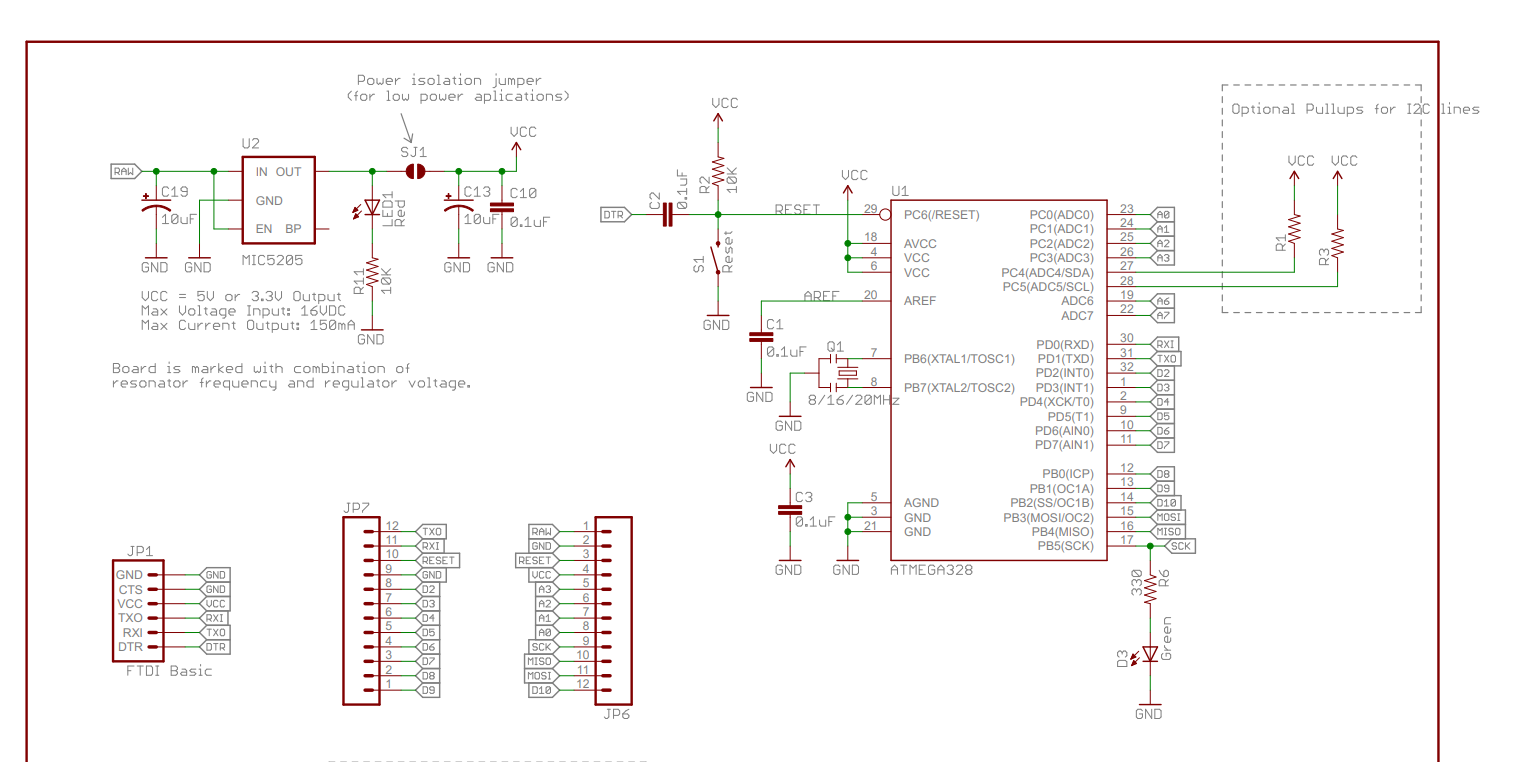
https://cdn.sparkfun.com/datasheets/Dev/Arduino/Boards/Arduino-Pro-Mini-v14.pdf -
For a "known good" starting point, you could pop the DIP atmega328p out of an arduino uno and practice burning your bootloader into that on a breadboard. If it gives you the same guff, then you know it's your procedure and not the chip that's at fault. Anyhow, as there's not really much that can go wrong, my WAG is that, based on @alphaHotel 's earlier comments requesting a reset-pin breakout (now baked into Version 3.0), it might have something to do with either the means or the assumptions under which your burner is accessing the reset pin.
Myself, I burn the bootloader and fuses in one of those spring-steel clamshell chip holders:
before soldering it onto the board, so I can't say that I've already done what you are attempting to do. IIRC, they cost only something like $10, but I do understand that simply knowing that doesn't really help you in the moment if you don't have one on hand already and you simply want to push forward with what you've got. -
For a "known good" starting point, you could pop the DIP atmega328p out of an arduino uno and practice burning your bootloader into that on a breadboard. If it gives you the same guff, then you know it's your procedure and not the chip that's at fault. Anyhow, as there's not really much that can go wrong, my WAG is that, based on @alphaHotel 's earlier comments requesting a reset-pin breakout (now baked into Version 3.0), it might have something to do with either the means or the assumptions under which your burner is accessing the reset pin.
Myself, I burn the bootloader and fuses in one of those spring-steel clamshell chip holders:
before soldering it onto the board, so I can't say that I've already done what you are attempting to do. IIRC, they cost only something like $10, but I do understand that simply knowing that doesn't really help you in the moment if you don't have one on hand already and you simply want to push forward with what you've got.@NeverDie said in Bootloading a barebones arduino:
For a "known good" starting point, you could pop the DIP atmega328p out of an arduino uno and practice burning your bootloader into that on a breadboard. If it gives you the same guff, then you know it's your procedure and not the chip that's at fault. Anyhow, as there's not really much that can go wrong, my WAG is that, based on @alphaHotel 's earlier comments requesting a reset-pin breakout (now baked into Version 3.0), it might have something to do with either the means or the assumptions under which your burner is accessing the reset pin.
I've got some DIP 328's. Good Idea. I'll try that. Your V1 board has access to Reset. I used an alligator pin to clamp on to the mcu side of the reset switch. So far, I have connected that to the RST pin of the USBasp.
Hello! It looks like you're interested in this conversation, but you don't have an account yet.
Getting fed up of having to scroll through the same posts each visit? When you register for an account, you'll always come back to exactly where you were before, and choose to be notified of new replies (either via email, or push notification). You'll also be able to save bookmarks and upvote posts to show your appreciation to other community members.
With your input, this post could be even better 💗
Register Login