Skip to content
  • MySensors
  • OpenHardware.io
  • Categories
  • Recent
  • Tags
  • Popular
Skins
  • Light
  • Brite
  • Cerulean
  • Cosmo
  • Flatly
  • Journal
  • Litera
  • Lumen
  • Lux
  • Materia
  • Minty
  • Morph
  • Pulse
  • Sandstone
  • Simplex
  • Sketchy
  • Spacelab
  • United
  • Yeti
  • Zephyr
  • Dark
  • Cyborg
  • Darkly
  • Quartz
  • Slate
  • Solar
  • Superhero
  • Vapor

  • Default (No Skin)
  • No Skin
Collapse
Brand Logo
axillentA

axillent

@axillent
Mod
About
Posts
355
Topics
18
Shares
0
Groups
1
Followers
9
Following
0

Posts

Recent Best Controversial

  • Small wall outlet sensor node
    axillentA axillent

    I've created this to have easiest way to establish environment monitoring across the house
    the idea is to have a wall outlet type plug with everything on board
    and I like to do small things
    The board is less than 50 x 50 mm
    It contains AC-DC power supply with resettable fuse, 3.3V LDO, arduino based on atmega328, radio, LED, and two slots, one for DS18B20 and the second one is for DHT11/DHT22

    IMG_2117.JPG

    The real consumption measured by RMS wattmeter is just 0.3W
    IMG_2118.JPG

    My Project

  • DIN Rail LEGO
    axillentA axillent

    Working prototype:
    1_1531564764819_Фото 14.07.2018, 13 20 07 sm.jpg 0_1531564764819_Фото 14.07.2018, 13 19 51 sm.jpg

    A LEGO set:

    0_1531564793598_Фото 14.07.2018, 13 29 46 sm.jpg
    0_1531564809164_Фото 14.07.2018, 13 32 29 sm.jpg

    Hardware

  • AC-DC at own
    axillentA axillent

    Everyone is need some kind of power supply for the project. Some time AC-DC is needed.
    From a few years of hobby I did a following list for myself:

    1. list item isolated AC-DC
      1.1 purchased as adapter
      1.2 purchased in separate box
      1.3 purchased to be put on PCB
    2. nonisolated AC-DC
      2.1 soldered capacitor based
      2.2 soldered switching inductor less
      2.3 soldered switching with inductor

    More or less a coprehensive listm, with proc and cons depending of the project.
    I prefer to solder things, but you see that I put all isolated as purchased. It is all about transformers.
    I'm scared about transformers - you need to properly design it, you need to wire it and build.

    Now I can tell that I do not scared any more)

    But to simplify start I ordered transformers build for the 5/12V output at power up to 3W. It is best sutable for most of my applications.
    0_1531562440011_Фото 09.07.2018, 23 11 04.jpg

    A testing board was created:
    0_1531562243611_acdc2.png

    soldered and tested:
    0_1531562450814_Фото 09.07.2018, 7 25 38.jpg
    0_1531562458616_Фото 10.07.2018, 0 29 43.jpg

    result of test as expected. at 13V output I coould get 3W of power with moderated heating

    schematic is based on LNK364

    By next step I will order PCB for my DIN Rail LEGO project:

    0_1531562601621_acdc.jpg

    Hardware

  • What did you build today (Pictures) ?
    axillentA axillent

    esp8266 based thermostat for heating system
    1_1541182358775_Фото 02.11.2018, 21 10 39.jpg 0_1541182358775_Фото 02.11.2018, 21 07 09.jpg

    General Discussion

  • Simple Mysensors clock
    axillentA axillent

    It was an idea a year ago to test an idea of simple and smart clock
    this clock will need no attention because it will be set and synchronized by MySensors support.

    The previous version a year ago was running my port to Plain C MySensors 1.3 and able to fit into atmega8
    Now it is upgraded to arduino + Mysensors 1.4.1 but for this I had to also upgrade to atmega328p (same as in arduino UNO)
    (google translated article is here https://translate.google.com/translate?sl=ru&tl=en&js=y&prev=_t&hl=ru&ie=UTF-8&u=http%3A%2F%2Fradiokot.ru%2Fcircuit%2Fdigital%2Fhome%2F176%2F&edit-text=)

    Simple - means simple. MCU itself is driving 7 segment display. I'm not using any external RTC clock but I'm using a special asynchronous mode of atmega328 and external 32768 so called clock crystal.

    DS18B20 and light sensor are on board.

    Display driver contains a software PWM with 0-15 level of the light intensity.
    Intensity is adjusted by light.

    schematics is here http://radiokot.ru/circuit/digital/home/176/01.png

    IMG_2150.JPG
    IMG_2151.JPG
    IMG_2152.JPG

    My Project clock

  • AC-DC at own
    axillentA axillent

    ready

    1_1534706270488_Фото 19.08.2018, 22 02 28.jpg 0_1534706270488_Фото 19.08.2018, 22 02 22.jpg

    Hardware

  • Custom made ethernet gateway based on atmega128
    axillentA axillent

    I need to have 4-5 ethernet gateways for my two installations (one for the apartment and one for the house)

    for this I'm developing a custom hardware
    it is a PCB with AC power supply, atmega128A, step-down for 5V (for atmega128), step-down for 3.3V (for radio and ENC28J60) ,
    4 leds (powe, error, TX, RX), ISP connector, 3.5mm jack to connect Serial, connector for NRF24L01 and connector for ENC8J60

    IMG_2057.JPG IMG_2058.JPG IMG_2059.JPG

    to use atmega128A a have to adjust Arduino configuration using some presets from the Internet.
    currently I'm running a standard Ethernet Gateway 1.4.1

    The plan is to add menu style configuration from the Serial connection for ethernet network parameters and for MySensors parameters.
    The plan is to propose a patch to MySensors to support Gateway ID - this will add support to the project to have multiple gateways without need of a hack. Otherwise devices from different gateways will conflict on the air.

    Hardware

  • How can I tell if my arduino mini pro is 3.3V or 5v?
    axillentA axillent

    if you can recognize the marking on xtal you will find 5v with 16Mhz and 3.3V with 8mhz

    Hardware

  • DIN Rail LEGO
    axillentA axillent

    assembled for particular applications
    0_1532866368413_Фото 29.07.2018, 15 09 59.jpg

    Hardware

  • MySensors battey board revision 1.0
    axillentA axillent

    I'm opening this topic for the discussion of the Mysensors board.
    We are very close to production this why an open discussion is very important to fix critical things and to understand your interest on the board.
    The price will very depends on volumes. But lets come to that later.
    Preliminary characteristics:

    50x50 mm size
    on board AAA battery holder
    very efficient step to power up at 3.3V from any single AAA (alkaline or Ni-MH/CD)
    atmega328p running at 1MHz from internal oscillator with ability to speed up to 8MHz on the fly
    NRF24L01 with antenna
    solar power switch, connect external solar panel 0.8-5.5V and solar will be the main power while solar voltage is higher than battery
    one I2C GROVE connector which can be used as a connector to A5/A4
    one GROVE analogue connector to A0/A1
    one GROVE digital connector to D2/D3
    high precision very low power I2C temperature sensor with ability to wake up MCU at temperature alertt
    one red LED

    to program you will need an external USB<->UART like you need to program pro-mini

    Announcements

  • Concept of a flexible but simple smart network
    axillentA axillent

    in details it is very different but by the idea it looks like TCP/IP stack
    Also by addressing, I assume 16 bit global address allows you to address any devices on the same network or other network through bridge or router. And there is no any requirement to have a controller. Devices are able to communicated directly. Controller is a device able to manage network config.uration by assigning ID's (very similar to DHCP). But. ID can be assigned manually and it is also possible to run ID-less configuration by using local or global broadcasts. For example wall switch can be configured to send Scene ID to LightScene brodcast address, and any lighting devices can receive this by brodcast and be activated based on scene ID instead of network address.
    Just to illustrate idea in more details I have other picture
    0_1509723823794_swi_network_types.jpg

    General Discussion

  • Red-green matrix information panel with real time clock
    axillentA axillent

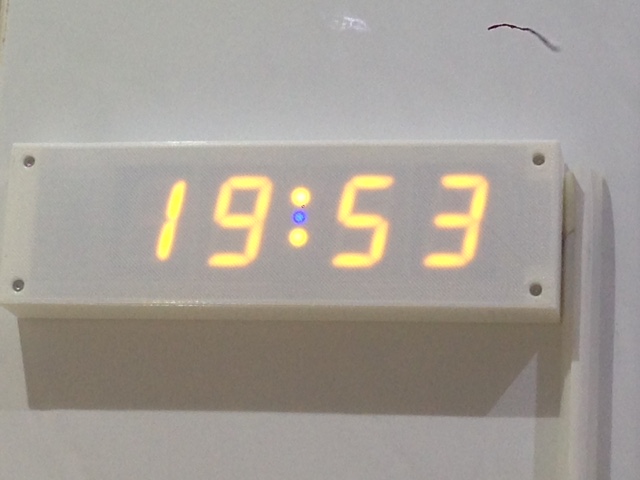
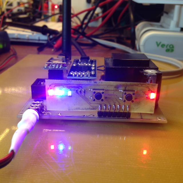
    More than a year ago I created this panel based on the RG 32x16 matrix from sureelectronics.
    I've posted a local article about it, google translation is here https://translate.google.com/translate?sl=ru&tl=en&js=y&prev=_t&hl=ru&ie=UTF-8&u=http%3A%2F%2Fradiokot.ru%2Fcircuit%2Fdigital%2Fhome%2F194%2F&edit-text=

    Just got time last night to migrate it from Plain C + MySensors 1.2 to Arduino + MySensors 1.4.1
    It was a bit trickier. I had to create a configuration of arduino based on atmega128. I used a way described here http://download.chip45.com/chip45-arduino-extension.zip (http://www.chip45.com/products/crumbuino-128_arduino_compatible_atmega128_module_board_usb.php)

    The C code was adjusted to C++. I keep usign C based libraries for RTC, BMP85 and for the matrix.

    Schematic is here http://radiokot.ru/circuit/digital/home/194/01.jpg and here http://radiokot.ru/circuit/digital/home/194/02.jpg

    Clock creates 3 child devices on controller side:
    Untitled.jpg

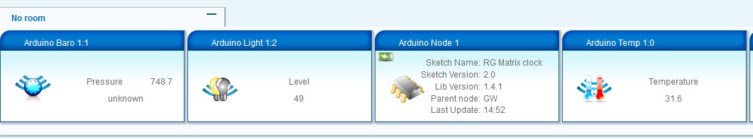
    Controller is updated with preassure, temperature, light level and RTC battery status

    This Lua is used to push Street temperature from vera to the Clock:

    local temp = luup.variable_get("urn:upnp-org:serviceId:TemperatureSensor1","CurrentTemperature", 61) 
    temp = temp*10.0
    luup.call_action("urn:upnp-arduino-cc:serviceId:arduino1", "SendCommand", {radioId="1;255", variableId="VAR_5", value=temp}, 430)
    

    61 is vera ID of wheather plugin current temperature device
    430 is Clock node vera device ID
    Similar Lua is used to populate Clock with average home temperature:

    local temp = luup.variable_get("urn:upnp-org:serviceId:TemperatureSensor1","CurrentTemperature", 384)
    temp = temp*10.0
    luup.call_action("urn:upnp-arduino-cc:serviceId:arduino1", "SendCommand", {radioId="1;255", variableId="VAR_4", value=temp}, 430)
    

    384 is vera ID of temperature average device

    you can also use VAR_1 to show a short text message on the panel
    VAR_2 is reserved to populate a numeric ID to third party connected to Serial1. I plan to setup a voice talking device. ID will call ID.wav or ID.mp3 file to play

    A short video is here
    http://www.youtube.com/watch?v=YOuO6zLDz6U

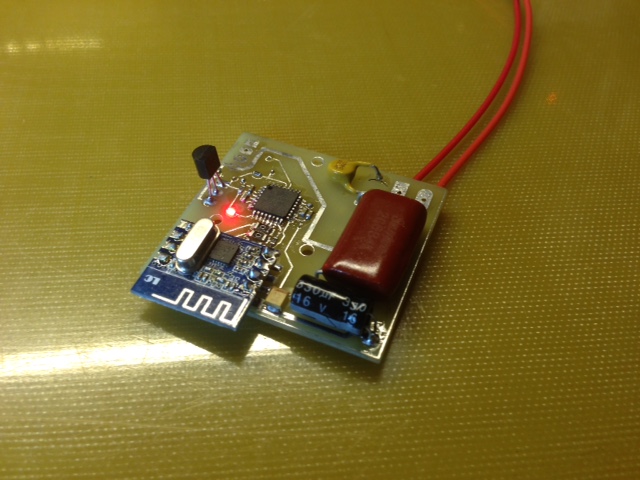
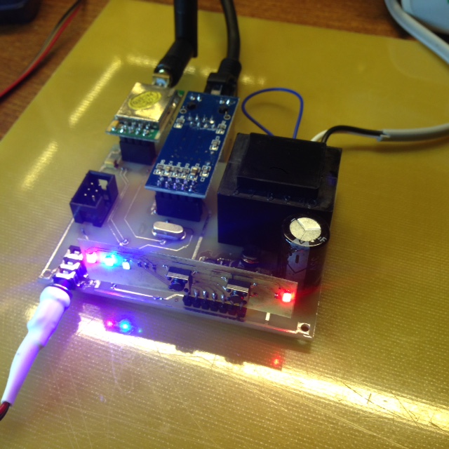
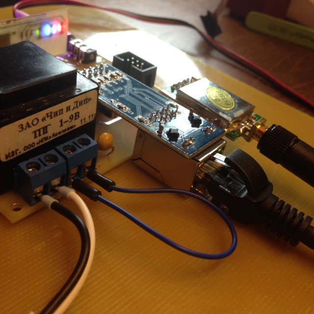
    My hardware kept without changes but it was a challenge to download arduino sketch because I use JTAG. The solution was found with Visualmicro and Atmelstudio. I setup an arduino sketch inside VisulMicro and a separate project for debug of the object file inside atmelStudio,. This allows me not only to upload using the JTAG but also to run a hardware debugging

    My Project

  • Sensor Node V2.0
    axillentA axillent

    @Tommy-Sharp "all in one" is one of our goal while working on the project boards

    Thanks all for ideas. We plan to have several project specific boards.
    First one will be the battery operated board designed for wireless sensors.
    Bellow is updated picture, should look better now.
    Sensor will be the digital one with precision 0.5C or better and very low power consumption

    Should we seriously support 5V from battery? For many applications 3.3V are sufficient and it will consume much less power from the battery.

    Relays, dimmers, SSRs will be managed by another board.

    mysensors.battery.jpg

    Hardware

  • MySensors battey board revision 1.0
    axillentA axillent

    I have news

    prototype of the board fully tested except radio
    stepup is working fine, power switching is working
    programming using external FTDI is working, schematics corrected to get rid from parasite power
    al I/O is fine
    battery and solar voltage measurement is working
    temperature sensor is excellent
    it was not simple to solder, the package is unbelievably small - 1.7 x 1.2 mm, 6 pins

    next and last is radio, going to solder it today
    фото 1.JPG

    Announcements

  • Reliable 5v buck converter recommendations?
    axillentA axillent

    @zboblamont said in Reliable 5v buck converter recommendations?:

    Surprised no recommendations offered, so trial and error it will have to be...
    Ordered up two XL4015 5A capable 5v boards before Trump modifies free postage ;) . $3 for two (one as a spare), doubt I could build even one at that price, just the 2 week/months slow boat to wait for.
    The general idea for the UPS being followed is per link text, the PSU, case and battery are easy enough local sourced, and plenty of time to decide whether USB or direct wiring is the choice of powering up the Pi..

    XL4015 will work for you. It is not the best performer but it will do a job.
    If I got your question correctly you do need a module to step down from acis battery (nominal 13.2V maximum 14.6) to 5V up to 3A contineous. Right?

    Best performers in steping down are so called synchronous rectifiers. The eseest to find as a modules is a module based on MP2307. Also a good selection will be a modules based on MP2315. Both are 3A maximum.

    General Discussion

  • Small wall outlet sensor node
    axillentA axillent

    Pictures bellow are virtual, under printing

    MySensors.Sens.atmega328-wall modelview-02.JPG MySensors.Sens.atmega328-wall modelview-01.JPG

    My Project

  • Future network topology (for discussion)
    axillentA axillent

    It is for discussion as a result of my discussion with @hek

    Main: The idea is to have multi-gateway and multi-physical-layer network.
    Multi-gateway means that it could be supported to have multiple Ethernet gateways in a single setup.
    Each gateway on one side (from the ethernet side) is a standard MySensors gateway, able to work with supported Home Controll Center using a plugin to that Center. On other side a gateway can manage a different physical transport.
    NRF24 can became a major standard but any other type can be supported as well and became a standard one.
    for example it can be wired RS485 or CAN, can be wireless RF433 or Zigbee. From the Home Controll Center it should be NO difference which physical layer is used to pass messages to the end node.

    Main: Ethernet side can be based on wired connection (wiznet etc.) or WIFI (ESP8266).
    New topology allows to setup a network of theoretically unlimited size (in terms of number of nodes and in terms of the physical area). The only limitation - an existing ethernet @WIFI infrastructure. You even can join segments located in different locations.
    Comparing to the current topology which is based on using NRF24 routing nodes.

    Probably: Because multiple gateways allows to be more flexible on the supporting area and supporting physical layer I will propose to get rid from routing nodes. This will reduce complexity of the Mysensors and improve it stability. Allows to focus on other things like reusing an existing ethernet@WIFI infrastructure

    Probably: Serial gateway can be kept for simple setup and for debugging purpose. But should be not in focus any more. Using universal ethernet gateways makes network more robust. For debugging a special IP sniffer can be used without interrupting other network components.
    Also sniffing can be used for a new version of the cloud@node (raspberry pi) to have light approach to listen to network and to log configurable events to the MySensors@Cloud

    Probably: Routing between different segments/gateways should be introduced. Some limitation can apply for certain physical layers (for example RF433 can be a one way layer, only for sensors like fire alarms, door sensors, motions sensors etc.)

    Probably: For NRF24 gateways the BASE radio address should contain gateway@node ID, so there will be no conflicts between sens@nodes from different segments and also it allows to build network with more than 254 sensors while not complicating sens@nodes
    Mysensors-Network-2015-01.jpg

    Hardware gateway network

  • MySensors micro step-up module revision 1.0
    axillentA axillent

    Through a discussion on the forum we found a potential interest to the step-up module with excellent battery saving capabilities
    We decided to present to you such a module
    It is actually same technology as will be used for MySensors Battery board, but it allows to choose any other board for your battery operated project.
    Module is using one of the best in class chip with hight efficiency and low quiescent current, this allows to run your device for longer time
    Module is designed with standard 2.54 pitch connector, can be easily connected using dupon wires
    Output voltage can be selected by switch 3.3V or 5V
    As power source you can use:

    • for 3.3V output - 1-2 alkaline, 1-3 NiMh/NiCd or solar up to 3.3V
    • for 5V - 1-3 alkaline, 1-4 NiMh/NiCd or solar up to 5V

    100mA output for 3.3V or 70mA for 5V are at minimum guaranteed

    Size is just 15x15mm

    Estimated retail price before shipping cost is $5
    Anyone interested?

    Prototype is on photo fully tested

    Untitled.jpg
    фото 12.JPG
    фото 1.JPG
    фото 2.JPG

    Announcements

  • Concept of a flexible but simple smart network
    axillentA axillent

    just published my libraries
    anyonw is welsome on review and comments https://github.com/axillent :

    • list item stavrp C++ multiplafrom suport library, platforms are at different level of support

    • list item smartletsp C++ smart devices network

    • list item swilib and integration of above two libraries with arduino framework

    General Discussion

  • Small wall outlet sensor node
    axillentA axillent

    @ServiceXp thanks)
    all this is simple, just a patient work

    Printed thing is a bit ugly comparing to the virtual one, but it's work is real
    IMG_2120.JPG IMG_2121.JPG
    http://www.youtube.com/watch?v=JG7gutD1oo8

    My Project
  • Login

  • Don't have an account? Register

  • Login or register to search.
  • First post
    Last post
0
  • MySensors
  • OpenHardware.io
  • Categories
  • Recent
  • Tags
  • Popular