@scalz thanks a lot for comprehensive recommendation. Will take a look, all is new for me
Posts made by axillent
-
RE: Looking for a good platform to programm webserver linked to webservices
-
Looking for a good platform to programm webserver linked to webservices
My iot network is requiering development a management console based on web interface
To control, analyse and configureAccess to network is throuth webservices
Any ideas of simple to start platform for this project?
My basic idea is php with some libraries
But may be a specially designed framework exists -
RE: AC-DC at own
@jeremushka I do have this footprint in altium but the library is big. do you know how to export a single element?
-
RE: Concept of a flexible but simple smart network
just published my libraries
anyonw is welsome on review and comments https://github.com/axillent :-
list item stavrp C++ multiplafrom suport library, platforms are at different level of support
-
list item smartletsp C++ smart devices network
-
list item swilib and integration of above two libraries with arduino framework
-
-
RE: Concept of a flexible but simple smart network
also from last
byteorder handling is build in
library allows to choose any order
I select bigendian because this is natural to my major MCU - STM8
on little endian platforms (like STM32, ESP8266 and ARM64) data is automatically translated -
RE: Concept of a flexible but simple smart network
for esp8266 i made an universal bridge application
it can be used for both:-
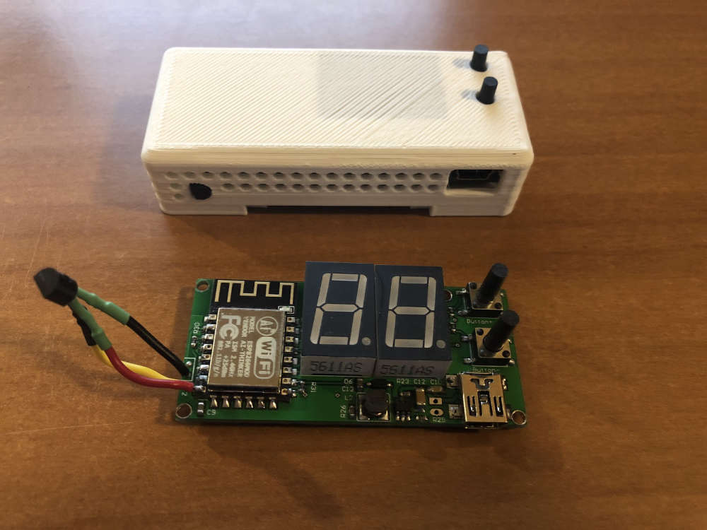
single node, esp8266 is running a final application. on the photo above my thermostats to measure room temperature, report it and to send ON/OFF commands to heaters
-
bridge. can be used to connect other type networks wirelessly to application server. UART is used for this + json translation. currently this is implemented to connect heating controllers located on each floor
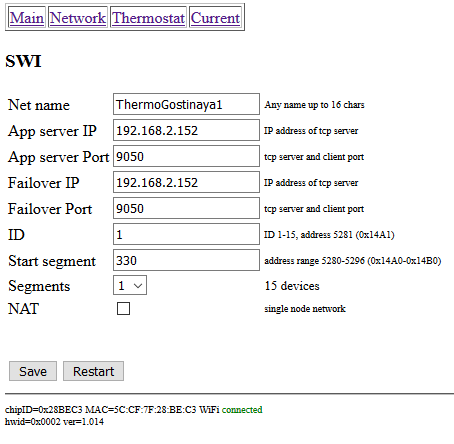
main and failover servers can be configured
also each node is configured to handle from one to a few network segments. this allows simple routing from application server back to node
esp8266 is using ArduinoOTA and zero hardcording.
after fresh programming esp creates AP and smartphone can be used to preconfigure a node
any updates are keeping configuration except major updates there stored structure can be affectedapplication server is also support MQTT translation
etc. it looks like a routing between my network and MQTT server
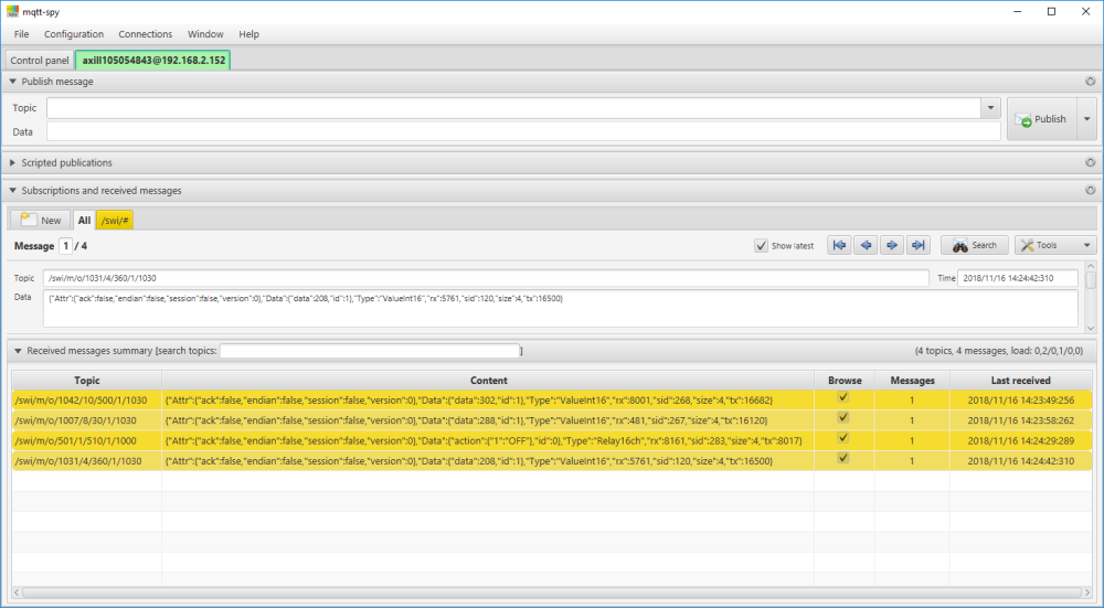
RX/TX adresing are mapped to MQTT topic while message is translated into JSON:
-
-
RE: Concept of a flexible but simple smart network
made a few steps forward
launched ESP8266 node & bridge and STM32 bridge and TCP/IP router based on linux (orangepi)
bellow is my working example
list of supported platforms:- STM8S/IAR
- STM32F0/Keil - draft
- ATMEL/Atmel studio - draft
- Arduino ESP8266
- Arduino STM32
- Linux/g++
i;m working on 2 libs. first is to handle platform dependant things. second is platform independant smart devices network
regardless platform and regardless communication hardware the framework allows to transfer messages using RX/TX notation with 16 bit global addressing.
Addressing is organized as 4096 segments where 4094 are 15 node segments each and 2 segments are for broadcadstingframework allows to connect potentially absolutelly different communication hardware
currently i'm running:- simple one wire (1 wire signal + 2 wire power) network
- wifi based nodes
- twisted pair connected ethernet devices
bridge between different types of network is organized on TCP/IP application server running currently on linux
etc. potentially allows to connect network segments regardless physicall location, only internet connection is requiredwhy i'm doing this? mostly for fan but also to implement 2 principles:
- application layer to be independant from hardware and transport. message format is universal and is the same regardless platform and communication hardware. Addressing is also universal. Application should not take care about intermediate specific, this is handled by other components
- avoid a central unit. each device can communicate with each device. the only central component is application server. but is is very simple, robust and reliable. failover is supported
My example:
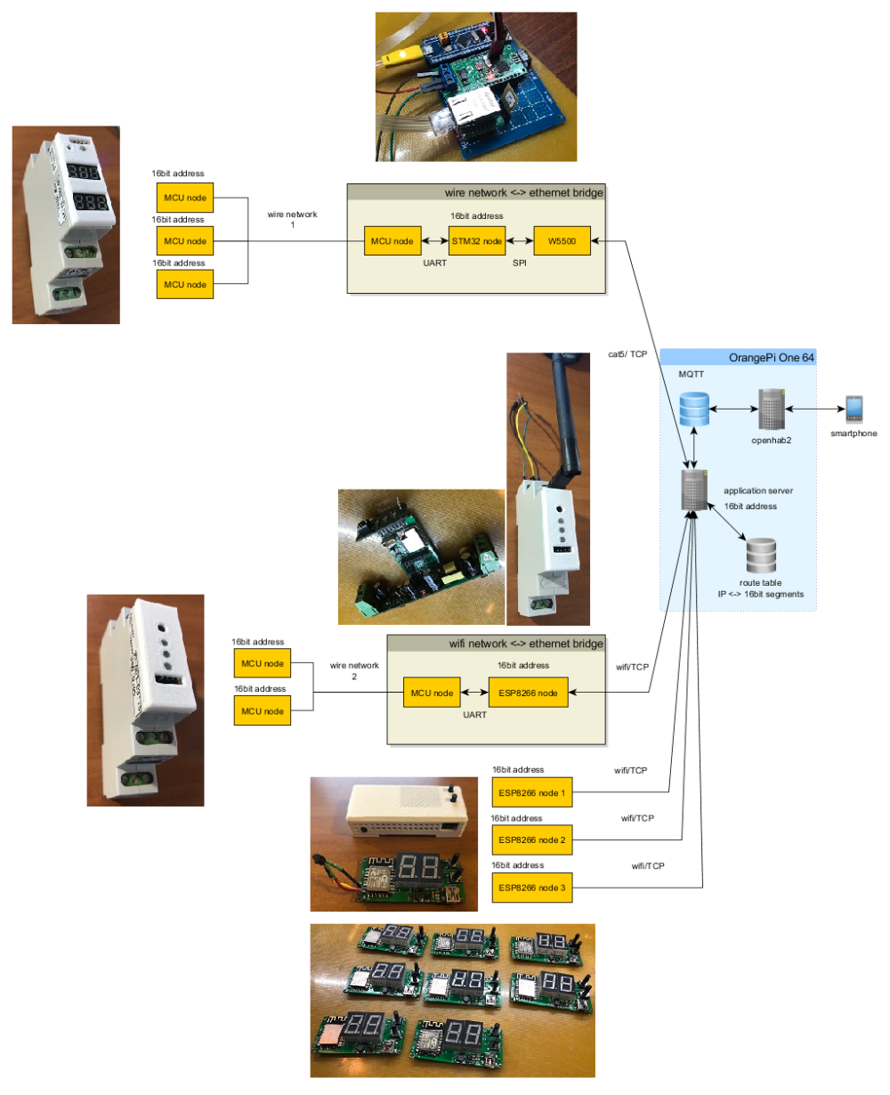
-
RE: What did you build today (Pictures) ?
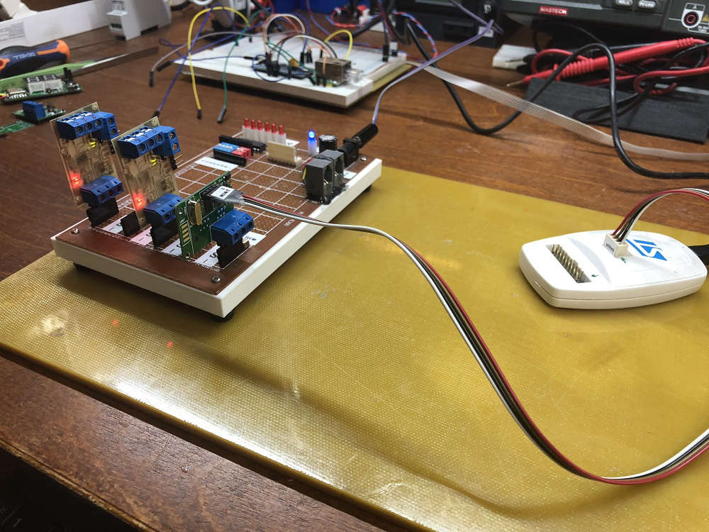
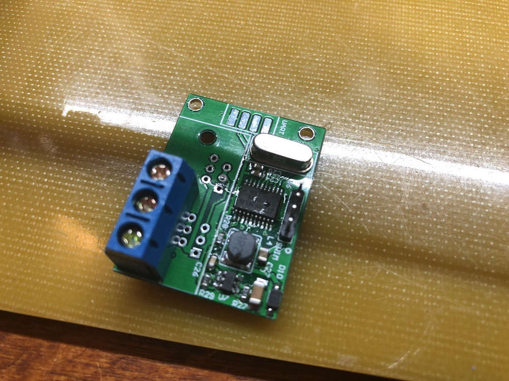
bridge from single wire (my w3p manchester based) to UART. will be used to bridge single wire network with Ethernet throuth ESP8266 or STM32 + Wiznet
second photo - development stand with w3p bus
-
RE: What did you build today (Pictures) ?
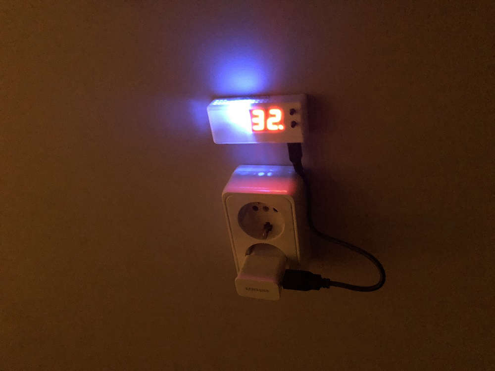
esp8266 based thermostat for heating system
-
RE: Reliable 5v buck converter recommendations?
@zboblamont said in Reliable 5v buck converter recommendations?:
Surprised no recommendations offered, so trial and error it will have to be...
Ordered up two XL4015 5A capable 5v boards before Trump modifies free postage . $3 for two (one as a spare), doubt I could build even one at that price, just the 2 week/months slow boat to wait for.
The general idea for the UPS being followed is per link text, the PSU, case and battery are easy enough local sourced, and plenty of time to decide whether USB or direct wiring is the choice of powering up the Pi..XL4015 will work for you. It is not the best performer but it will do a job.
If I got your question correctly you do need a module to step down from acis battery (nominal 13.2V maximum 14.6) to 5V up to 3A contineous. Right?Best performers in steping down are so called synchronous rectifiers. The eseest to find as a modules is a module based on MP2307. Also a good selection will be a modules based on MP2315. Both are 3A maximum.
-
RE: Your best advice on buying components?
@fredswed I think to care too much about selecting source of items.
I also tried different ones including ebay, mouser, farnel, sparkfun etc. end up to use only (mostly) ali.
Spending time to analyse goods presented you will find that most sellers are providing same goods.
The only difference between them is price and quality of service.Finally I refused to keep track on a particular sellers. Each time I need something I do search for best price and most sells and looking into ratings and customers feedback refuse worstest ones. Each such search requires just a few minutes to end up with purchase.
In practice using such approach in most cases you will purchase from a small set of sellers. But there is no need to depend on them. In case of mistake in selecting seller you will call for your money.
All this for DIY purpose. Time is not a critical issue.
If you are about doing some commersial staff it is always a different story -
RE: Your best advice on buying components?
@flopp In my understanding all this DIY shops are managing whemselves. So wharegousing strategy is up to concrete store.
From my experience I'm getting some parcels from EU, many from Latvia, some from Finland and some from others. -
RE: Concept of a flexible but simple smart network
just to illustrate how translation is working
you do not need direct logic match between abstract layer and the layer of used interfacehere is how translation is working between my network and MQTT broker:
bellow is initialization of 2 different nodes attached to 2 different interfaces, one to TCP/IP network, other to MQTT broker
it is a code from linux application server//----------------------------------------------------------------------------------------- // Nodes //----------------------------------------------------------------------------------------- // --- inet typedef Smartlets::Common::RouteTableFile RouteTable; typedef STAVRP::Linux::TCPDrv<0> TCPDrv; typedef Smartlets::Interface::Translator::INet<Message, TCPDrv, RouteTable> TranslINet; typedef Smartlets::Interface::P2P<Message, TranslINet, 16, 16> InterfaceINet; typedef Smartlets::Node::NodeBasic<Message, InterfaceINet, ApplInet> NodeINet; // --- mqtt typedef Smartlets::Interface::Translator::Mqtt<Message> TranslMqtt; typedef Smartlets::Interface::P2P<Message, TranslMqtt, 16, 16> InterfaceMqtt; typedef Smartlets::Node::NodeBasic<Message, InterfaceMqtt, ApplMqtt> NodeMqtt;
Inside Translator:Mqtt the following is used for example inside TX method (sending message):
static bool TX(const Message& msg) { char key[128]; if( msg.header.tx.IsBroadcast() ) sprintf(key, "/%s/bc/o/%d/%d/%d/%d", data.swi_domain.c_str(), msg.header.tx.GetBroadcastID(), msg.header.rx.GetNetSegment(), msg.header.rx.GetNetDevID(), msg.header.type.type); else sprintf(key, "/%s/m/o/%d/%d/%d/%d/%d", data.swi_domain.c_str(), msg.header.tx.GetNetSegment(), msg.header.tx.GetNetDevID(), msg.header.rx.GetNetSegment(), msg.header.rx.GetNetDevID(), msg.header.type.type); std::string payload = json_ext::FromMessage(msg); data.drv.TXPut(STAVRP::Linux::MqttEntry(key, payload)); return true; }``` and this is how it is finally bridged between:
while(1) { //--------------------------------------------------------------------------- // loop inet //--------------------------------------------------------------------------- if( NodeINet::Loop() ) { Message msg = NodeINet::RX(); Logger::root() << log4cpp::Priority::DEBUG << "inet-> tx=" << msg.header.tx.id; NodeINet::CommitRX(false); // --- routing if( NodeINet::TX(msg) ) { Logger::root() << log4cpp::Priority::DEBUG << "inet->inet TX OK"; // delayed queue } else { Logger::root() << log4cpp::Priority::ERROR << "inet->inet TX failed"; } if( NodeMqtt::TX(msg) ) { Logger::root() << log4cpp::Priority::DEBUG << "inet->mqtt TX OK"; } else { Logger::root() << log4cpp::Priority::ERROR << "inet->mqtt TX failed"; } } //--------------------------------------------------------------------------- // loop mqtt //--------------------------------------------------------------------------- if( NodeMqtt::Loop() ) { Message msg = NodeMqtt::RX(); Logger::root() << log4cpp::Priority::DEBUG << "mqtt-> tx=" << msg.header.tx.id; NodeMqtt::CommitRX(false); if( NodeINet::TX(msg) ) Logger::root() << log4cpp::Priority::DEBUG << "mqtt->inet TX OK"; else Logger::root() << log4cpp::Priority::ERROR << "mqtt->inet TX failed"; } sleep(1); }```
-
RE: Concept of a flexible but simple smart network
@kimot the main idea of all my project is to manage network abstraction layer regardless hardware
only translation + driver layers are hardware related, but them allow to transfer logical layer data throuth any physical hardware
my 16bit addressing could be translated to addresses used by your hardware to keep handle communication based on hardware advantages.I just launched a network with translation throuth Ethernet/TCP with application server running on orangepi
Working pretty well. On logical level it is always 16bit addressing with broadcasting support.
developing device you should not take care how message will reach another device
this is handled while developing appropriate translations/drivers on bridge side.bridge - a device connecting 2 or more different physycal layers.
it is also allows to crate a building blocks.
For example I'm running ESP8266 with TCP interface to network on one side and UART&JSON interface on other side
attaching MCU to ESP by UART a can connect any kind of network to my network -
RE: Concept of a flexible but simple smart network
@zeph yes and no. it is very very simple hardware, similar to LocoNet. allows to transfer a few kbit/sec on single wire (w3p - 3 wire VCC + Signal + GND) using 1 npn transistor + 4 resistors at absolute minimum
-
RE: DIN Rail LEGO
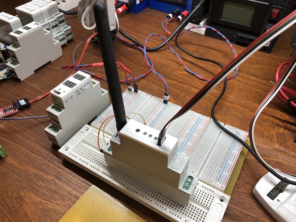
wifi router got a firmware and box
can be cloned as many as needed, one per simple network segment
it is managing automated routing between segments -
RE: AC-DC at own
@jeremushka said in AC-DC at own:
Thanks for the answer. i will play with this LNK component. never used it before. I am curious to know the performances of it.
for your design, you have added others functions on your PCB ? such as DC-DC converter ... etc.. ?my DIN desing is universal. it is for the set of different devices with common 12V power
dc-dc is used to feed MCU from 12V -
RE: AC-DC at own
@jeremushka said in AC-DC at own:
some questions regarding the schematics:
- does TVS diode 600W 5V is efficient enough? or absolutely need cut off at 160V such as 600W 160A ?
- for the Fuse, a slow fuse 10A is enough i think, isn't it?
TVS need to be for 120-160V in case you supply 230V AC. You can refer to linkswitch designer for your specific needs.
The purpose of this TVS is to be a snubber because of inductive load. Instead of TVS an RC snubber could be used.it is 3Watts supply, 0.5-1A slow fuse is fine
-
RE: Concept of a flexible but simple smart network
some more details about addressing
global adress is 16 bit number. 12 most significant bits are defining network segment number while 4 less significant bits are providing nodeID
section 0xFE00-0xFEFF is reserved for local broadcasting, 0xFF00-0xFFFF - for global broadcasts. Etc. 256 broadcasts of each type
segments and differenciation between local and global broadcasts are needed for efficient support of bridging and routing.
bridging is a simplified version of routing. bridging is connecting network segments on different physycal inrterfaces while routing can assume to bypass many physical interfaces between (routing throuth).
one of the bridge example is a link between wired interface and MQTT.
one of the routing example is a link between 2 wired interfaces across public Interneteach network segment can have 15 nodes. nodeID = 0 is a special local segment broadcast addressing all devices in segment.
each physical interface can have several segments, etc. there is no limitation to have 15 nodes on physical interface. you just add as many segments to interface as you need to have devices
-
RE: AC -DC transformer sourcing
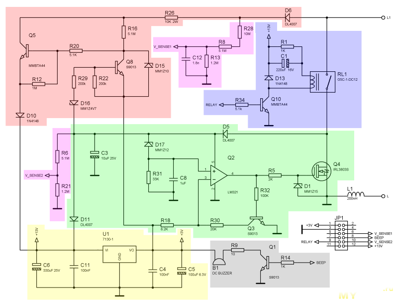
@jeremushka if you will check datasheet on lnk3002 you will find that it is a regular none isolated acdc
The know how of this design for 2wire installation not in transformer, it is in disconnecting load on positive wave in case of voltage dropA saw similar desing without transformer, it was a re engineering of radio switch
-
RE: AC -DC transformer sourcing
@jeremushka am i got it correctly that you need 5v without having neutral wire?
I never saw solutions for that type of power source using transformers, regular 50hz or even switching
There are a few different types of schematics i saw, but all are transgormer less
-
RE: AC-DC at own
@jeremushka said in AC-DC at own:
Thanks. What is the purpose of the inductor at the output of the circuit? why not to use one also after the bridge rectifier?
inductor at output is to reduce riple
on hight voltage side will be better to put filter but there is no place for it
inductor as such will not bring too much value -
RE: AC-DC at own
@jeremushka for sure
schematic is standard, simplified version from datasheet
D8, D11 and R22 are optional, it is to be able to source power from different sources (for example different phases, or from main power and from generator).
D12 I'm using 11V to have output at about 12.1V -
RE: DIN Rail LEGO
this is going to be WiFi router from local 3 wire net to Internet or remote ioT net
-
RE: DIN Rail LEGO
A new design, just ordered PCB. An upgrade of previous MCU PCB:
- STM8S105C6
- EEPROM I2C 512K - to support OTA
added:
- ADC1115
- DS3231
- ESP-M1
- NCP1529 for 3.3V
- supercapacitor to support RTC
- SH1.0 connector to flash ESP
- 2 pin on base 1
- 2pin on base 2
with soldered ESP will became a local net router, can connect local wired network to Internet and MQTT
also will run RTC application on local and global net
-
RE: DIN Rail LEGO
@gohan Price is very depends on volume. 10 pcbs are costing me $10 for the set while 50pcs costing $15
Etc. 4pcb for the unit is $1.2-4
Box +$1.3
The rest is BOM, also very depends on volumes and on a unit specific details. -
RE: AC-DC at own
@koresh if you need gerber let me know, i will download. I need to note that DIN is designed for a particular design of the cover
Share please where it is possible to order customized transformers.
I do have all things to build transformers myself. It is an alternative way
-
RE: AC-DC at own
@koresh transformers is not a big deal but selection is very limited. I only found one item with reasonable pricing and sutable parameters. You can find it on ali by name EE10-A1
-
RE: AC-DC at own
@koresh pcb picture is presented. Please clarify what else you want to see. All is open
-
AC-DC at own
Everyone is need some kind of power supply for the project. Some time AC-DC is needed.
From a few years of hobby I did a following list for myself:- list item isolated AC-DC
1.1 purchased as adapter
1.2 purchased in separate box
1.3 purchased to be put on PCB - nonisolated AC-DC
2.1 soldered capacitor based
2.2 soldered switching inductor less
2.3 soldered switching with inductor
More or less a coprehensive listm, with proc and cons depending of the project.
I prefer to solder things, but you see that I put all isolated as purchased. It is all about transformers.
I'm scared about transformers - you need to properly design it, you need to wire it and build.Now I can tell that I do not scared any more)
But to simplify start I ordered transformers build for the 5/12V output at power up to 3W. It is best sutable for most of my applications.
A testing board was created:
soldered and tested:
result of test as expected. at 13V output I coould get 3W of power with moderated heating
schematic is based on LNK364
By next step I will order PCB for my DIN Rail LEGO project:
- list item isolated AC-DC
-
RE: Concept of a flexible but simple smart network
@dbemowsk each layer does it's job
bridge just creates a bridge
will it do a translation between depends on translation layer
translation job can be about translation of address or translation of data form or even both
all this depends on the goal but brings wide flexibility -
RE: Concept of a flexible but simple smart network
yes, to address devices across different network segments you need a global ID
but there is a trick... Please see the first picture. It is a layer called Translator.
it is possible to translate non-global ID to global and back and this will allow to create a bridge -
RE: Concept of a flexible but simple smart network
Not that important. But there is no stick to Arduino. It is multiplatform based thing-set. Atmel + STM8 + STM32 are supported. ESP is comming
-
RE: Concept of a flexible but simple smart network
based on this concept I make a text based console which is actually Super Application, application one is 3 wire physical interface with manchester encoding, application 2 is UART console connected to VT220 terminal. Super Application bridges to networks together. By adding Broadcast with accept to All messages broadcast I allow Bridge to pass all the messages between two networks
// --- bridge application typedef Application::Bridge<msg_type, w3p_appl, uart_appl> bridge_appl; //------------------------------------------------------------------------------ // Variables //------------------------------------------------------------------------------ //------------------------------------------------------------------------------ // Main //------------------------------------------------------------------------------ int main() { mcu::Init(); ep_id::SetDefault(Message::ID(THIS_NET_SEGMENT_ID)); ep_key::Set(); bridge_appl::Init(); timer::Start(); led2.Set(); mcu::InterruptEnable(); uart_transl::SetID(ep_id::Get()); uart_transl::Print("\n\n\x1b[31m--- Console v1.0 started\x1b[30m"); while(1) { bridge_appl::Loop(); mcu::InterruptWait(); } }
All is plug & play. Etc. it requires NO modification of basic library to create this console. A typical session bellow:
-
RE: Concept of a flexible but simple smart network
in details it is very different but by the idea it looks like TCP/IP stack
Also by addressing, I assume 16 bit global address allows you to address any devices on the same network or other network through bridge or router. And there is no any requirement to have a controller. Devices are able to communicated directly. Controller is a device able to manage network config.uration by assigning ID's (very similar to DHCP). But. ID can be assigned manually and it is also possible to run ID-less configuration by using local or global broadcasts. For example wall switch can be configured to send Scene ID to LightScene brodcast address, and any lighting devices can receive this by brodcast and be activated based on scene ID instead of network address.
Just to illustrate idea in more details I have other picture
-
RE: Concept of a flexible but simple smart network
An Example of simple device, application configuration:
// --- Smartlets typedef Message::Message<20> msg_type; // --- Options // w3p driver typedef HandlerPortD<ExtIntMode::FallingRising> pinchange_drv; typedef PortD<6, PinMode::Interrupt> w3p_rx; typedef PortD<5, PinMode::Inverse | PinMode::OutputPushPull> w3p_tx; typedef Timer2<mcu, 0, 6, 1000> w3p_timer; typedef Driver::W3P<w3p_rx, pinchange_drv, w3p_tx, w3p_timer> drv; // translator typedef Translator::W3P<msg_type> transl; // dispatcher typedef Dispatcher::P2P<msg_type, transl, drv> disp; // application typedef Feature::Basic1<msg_type, disp, ep_id> basic1; typedef Feature::CallBackByType<Message::Type::LightScene, msg_scene_cbk> scene_callback; typedef Feature::CallBack<msg_type, scene_callback, basic1> callback; typedef Feature::Basic2<msg_type, disp, button, led1, callback> basic2; typedef Application::Application<msg_type, disp, basic2> appl;
And simple main, this one supports 2 channel relay functions and 2 NTC sensors
int main() { mcu::Init(); ep_id::SetDefault(Message::ID(THIS_NET_SEGMENT_ID)); ep_key::Set(); appl::Init(); adc::Start(); timer::Start(); mcu::InterruptEnable(); var.timer = 10; var.timer1 = 60; var.timer2 = 60; struct { int temperature1, temperature2; } prev; while(1) { appl::Loop(); if( !var.timer ) { var.timer = 10; if( !var.timer1 || abs_int(prev.temperature1 - var.temperature1) > 10 ) { Message::Value msg(100, var.temperature1, Message::Value::TemperatureInt16); if( appl::Tx(Message::ID(Message::ID::Value), msg.Type(), msg, msg.Size(), false) == Message::State::TxOK ) { // message is to be send prev.temperature1 = var.temperature1; var.timer1 = 60; } } if( !var.timer2 || abs_int(prev.temperature2 - var.temperature2) > 10 ) { Message::Value msg(101, var.temperature2, Message::Value::TemperatureInt16 ); if( appl::Tx(Message::ID(Message::ID::Value), msg.Type(), msg, msg.Size(), false) == Message::State::TxOK ) { // message is to be send prev.temperature2 = var.temperature2; var.timer2 = 60; } } } mcu::InterruptWait(); } }
call back:
bool msg_scene_cbk(const uint8_t& msg) { const Message::Relay& data = *(const Message::Relay*)&(&msg)[sizeof(Message::Header)]; switch( data.channel ) { case 0: relay1.Set(data.relay); led2.Run(1, 5); return true; case 1: relay2.Set(data.relay); led2.Run(2, 5); return true; } return false; }
-
Concept of a flexible but simple smart network
Doing my staff and doing mysensors, thinking about others I came intp conclusion that smart network required to be more abstract, it's basics should be in logic disconnected from hardware realization. From a long long thinking I made a concept I'm currently working on. I will be glad to share and discuss it to get different views.
Abstracting requires to split all into separate levels starting from application and dropping down up to hardware. It can be done in different ways. I will describe here my way.
First of all the message. It very common to have here a header with RX & TX ids and message type. But it should have nothing about underling like CRC sum. The underling is coming on lower level. This allows to write an application which does not depends on hardware.
So to start I present a layering diagram
Layers are listed here from left to right:
-
Super Application. This is top-top abstract layer as a cover of regular application. Example are the Bridge (interconnects two networks) and Router (interconnects with routing 2+ networks)
-
Application. This is a regular application required by any smart device. It allows you have a network connected device. It is so common that it can be used for whatever you want and you can plug so called Features into it to extend its functionality without re-programm the applicariton. See Features bellow.
-
Application Feature. This is a plug-and-play extensions to Application. Examples are:
- basic1 allows the device to auto assign ID or to have ID assigned manually by network command
- basic2 contains support for "red" button and indicating LED. LED represents Application status: Normal, NOIDUssigned, WAITCOMMAND. Button allows enter/leave WAITCOMMAND status. This status allows device to receive messages with special WAITCOMMAND broadcast address regardless its own ID. This one is similar as Inclusion status for ZWave devices.
- callback. regular application allows you to read network messages by ::RX method. callback Feature allows you to define per message type callback functions
- broadcast. regular application address device by its direct ID. broadcast Feature allows you to define a list of special broadcasts for device to have an alternative addressing. For example you can put RTC clock inside your network and any device can request clock source without knowing the source ID
- Dispatcher. This Feature organize needed logistic for incoming and outgoing messages. Example:
- P2P peer to peer network. All outgoing messages are send immediately to hardware
- M&S master and slave. Outgoing messages from slaves will be send only on session start request from Master. This for example can be used on half-duplex RS485 networks
-
Translator. This one is very close to hardware. It translate abstract standard message from-to hardware layer. For example it can put the message into cover with CRC checksum if underling interface requires this. Other example - text console. All messages are translated to text for manual monitoring and also there is a possibility to send message
-
Driver. This one deals with hardware directly or using specified hardware library. Examples:
- NRF24
- RS485
- UART
-
-
RE: 230V power supply to Arduino
@croc sorry to be so late in answer
this as an application note 0_1479681329040_an37-linkswitch.pdf
My design is equal to the schematic posted by @Stephan except an input filter. According to an37 I'm using 2uF + 1uH +2uF as input filter.
I'm using a compact X7R 1uF x 450V purchased from aliexpress. Instead of RF1 I'm using PTFE (a resettable fuse) 40mA @ 250V
D3 + D4 are M7
D1 is US1J / ES1J
C2 & C3 are also X7R -
RE: Best IDE to use for MySensors projects
atmel added arduino support to their latest atmel studio v7
not tested yet, but it should be also an option -
RE: MySensors with Atmega8(L) ?
you will probably need to hack&cut a library to reduce a required flash
I would recommend you to reconsider usage of atmega8, otherwise you will need to spend a lot of time to fit any upgrade
I had such an experience. I was translating Mysensors to Atmel Studio and that allows me to fit sensors & clocks into atmega8.
But as Mysensors is under fast development it became too complicated to follow. -
RE: 230V power supply to Arduino
@themoloch sure
I'm using a standard schematic from the datasheet. It is also a separate application note exists with recommendation on how to optimize input filter for low loads. The board on the picture for example uses 2x1uF + 2x1uF + 1mH as input filter -
RE: 230V power supply to Arduino
@scalz said:
I'm using similar one, it is also called 3 x1 W Led driver and by my measurements provides 300mA and 17V without load
I use 220uF to filter its output and I use 78L05 to regulate down to 5V. This can give up to 5V@40mA output. The restriction is a heating desipation rating for 78L05.
For higher loads I would recomment to use DC stepdown. With DC stepdown you can get up to 5V@650mA with 80% efficiency -
RE: Where do you buy your Hardware?
@Florian-Strempel world wide you can purchase from aliexpress or ebay
I prefer to use aliexpress. Many sellers on aliexpress are having hubs in US, Europe and Asia and you should not be surprised to get parcel from shorter distance.This is a most cheap choice but make sure to choose a seller with proved and good reputation. Quality can be an issue.
Also there some well known DIY stores on the market with wold wide shipping, for example - sparkfun.com, http://imall.iteadstudio.com/, http://www.seeedstudio.com/
They sell actually the same as sellers on ebay/ali but it is a "preselection" of a right quality.Also there well known parts distributors with wold wide network Farnel, DigiKey, Mouser.
This is most expensive but of best quality products.
Farnell for example is selling only original raspberry.Choose at you choice based or not based on your location.
Regards,
Alexander -
RE: 110v-230v AC to Mysensors PCB board
@scalz two wire ligting menas that a wall switch is feeded only with two wires. One wire is a L source and second wire is from the load (from the lamp). Classical switch just need to short this two for the light to startup. In this case ay smart switch need some advanced technique on to power itself. For example fibaro dimmers do so.
Do you plan to use single 48V power supply for the lighting? I'm working on the prokect for the guest house because it is just on building stage. I have a plan to use single 48V AC-DC power source with wired mysensors network. I will use 3 wires accross all lamps and switches and sensors. They will communicate with each othe P2P using a single wire interface based on Manchester encoding. I also plan to have Mysensors gateway.
-
RE: 110v-230v AC to Mysensors PCB board
It was another discussion http://forum.mysensors.org/topic/687/230v-power-supply-to-arduino/23
You are adding a valuable solution.
This module looks very interesting in case it will meet all stated characteristics,I also thinkin on something small to fit into standard wall box but I have some complication.
I need a solution for 2-wire lighting, It is because All lighting in my house is a two-wire system.
Otherwise I will need to feed third wire to each wall box. -
RE: Vintage bulb
cool thing
I saw similar in some cafe
looks nice
just make sure that you have alternative light for lighting ) -
RE: Power bus
you are on a right way)
take into account that long wires are always subject of the voltage drop
I will suggest you to consider a higher voltage for the bus, 12V or even 24V
and you will need step-down before each arduino to get 5V or 3.3V
there are cheap and small step-down can be purchased on ebay or alithe advantage of the step-down comparing to linear regulator is current transformation - step-down not only drop voltage down from 12V to 5V (for example) but also decrease current on a bus side. As lower current as lower voltage drop across the bus
RS485 could be a good choice for the communication. definitely RS485 at some point will be a standard option for mysensors, and a gateway from RS485 to a controller will be also a standard option.
I personally working on a similar project. In my case power will be 48V, I will use just 3 wires, In my case 48V will source not only sensors but also LED light. This why I choose a bit higher voltage
-
RE: Australia might criminalise teaching of encryption
the history is a circle
http://en.wikipedia.org/wiki/History_of_cryptography
remember the story of PGP -
RE: Gateway device
@tbowmo sure
in general arduino can handle any AVR8 from atmel
my comment was about "not a standard arduino MCU" means it is not described inside official board.txtif i'm not mistaken atmega644 (same family as atmega1284) is used in reprap and it is arduino too
-
RE: How can I tell if my arduino mini pro is 3.3V or 5v?
@Alco-van-Neck said:
Oh en not 100% waterproof visual: all my 3.3 V arduino mini pro's do have a RED reset switch on it. the 5V arduino's got a white reset button
this criteria has nothing to do with an official arduino pro mini
http://www.arduino.cc/en/Main/ArduinoBoardProMini -
RE: Gateway device
@tbowmo said:
giving higher throughput
ohh) the logic coming from PC world not working here. regardless how many SPIs you will initiate MCU will handle them in a sequence.
but any way it could be a benefit
for example you can avoid SPI fix if there will be exclusive SPI port used for wiznetSo many parameters to choose from
on other hand it is good. atmega644/1284 are from later generation having more features. 16k RAM is a very good thing, gateway potentially could be hungry on RAM usage. The disadvantage is missing 256k version
for last resort I will ask @hek to request quotes from partners to understand better the price difference.
-
RE: Gateway device
@tbowmo I'm not sure that arduino SPI library can deal with USART as SPI at all
but it could be no problem to write down a peace of a new code to use USART as SPIwhy you need 5 SPI's?)
-
RE: How can I tell if my arduino mini pro is 3.3V or 5v?
if you can recognize the marking on xtal you will find 5v with 16Mhz and 3.3V with 8mhz
-
RE: Gateway device
@tbowmo 20mhz should cost very similar to 16mhz, price is not an issue in this choice. Frequency is one of the parameter you will need to put inside boards.txt, it could be no issue to replace 16 by 20
ok I see. if soldering is an issue there is also atmega1281/atmega2561 pin compatible having TQFP64 package while been fully compatible with atmega1280/2560 (they do have single datasheet). Their maximum xtal is 16mhz
-
RE: Gateway device
@tbowmo thank! it is a good job done!
some questions/comments- w5100 SPI fix is already inside modern arduino ethernet shield http://www.arduino.cc/en/uploads/Main/arduino-ethernet-shield-06-schematic.pdf
do you think it is needed? what kind of the shield your are looking for? - why not to put 20MHz crystal to give some more performance to the gateway?
- USB is normally can supply not more than 500mA, are you sure it will be sufficient? DC-jack probably will be also good to have. ESP+wisnet could be hungry for the supply
- why atmega1284? it is not a standard arduino choice but could costs on a level of 1280. atmega128 is the lowest cost 128k AVR. If we are sure 128k will be sufficient in the future I will select atmega128 because of cost or atmega1280 because it is standard for arduino
And also I will consider atmega2560 to have a maximum possible resources (not only flash but also RAM)
- w5100 SPI fix is already inside modern arduino ethernet shield http://www.arduino.cc/en/uploads/Main/arduino-ethernet-shield-06-schematic.pdf
-
RE: Camera as a sensor
@bjornhallberg very nice setup! my congratulations!
for DIY you did it pretty well
but cost vise I do not see how this can be more efficient comparing to foscam -
RE: Camera as a sensor
@Moshe-Livne said:
@Mickey this device is a gsm hotspot generator. it connects to a USB GSM dongle and allows you to connect to it either wired or wirelessly. I have never seen devices like the ones you mention. they could be a good solution
do not stick to it's original application
the idea is that open-wrt can run on this small things. Open-wrt is a linux type system, you can program it very similar to RPI
it is very cool if any camera working example exists for open-wrt -
RE: Camera as a sensor
@Moshe-Livne said:
@axillent yes. just a door or hall sensor that will be triggered by the PIR, take a snapshot (or maybe several in 10 sec increment) and send them to the home automation system.
OK, I see. Do you want both PIR and camera module been connected to the same device? If yes this could have not much todo with mysensors. It can be regular arduino or rpi sketch sending pictures by FTP or email.
If you want to have PIR on other device you can use mysensor to sens PIR and trigger other device to take pictures using mysensors radio -
RE: Camera as a sensor
@Moshe-Livne said:
@axillent no, no.... as I said, i want to use it as cheap entrance device. PIR is good enough to trigger the response
can you explain exactly what do you want?
PIR is triggering event and someone is taking picture at this moment? -
RE: Camera as a sensor
@Moshe-Livne said:
@axillent I live in NZ.... 45$ shipping....
there are many foscam clones shipping free from China starting at $50
-
RE: Camera as a sensor
@Moshe-Livne said:
@axillent i was thinking using PIR for detecting motion, snapping a shot and sending it. you are right about the ram - i would need sd card reader probably
PIR? it is something different. You need a clear view on what you want. From you first post I realized that you want to detect motion by analyzing camera output etc by analyzing images. Using PIR is very different
-
RE: Camera as a sensor
@Moshe-Livne IP cameras are starting from $50. they have a processor able to process images at a good speed for you to trigger a motion event in a second after real motion starts. Using camera module you will have to do the same - processing images one by one to detect changes and this will trigger event. You will need at least a RAM to store a series of images at your camera resolution. RPI should be sufficient for this, but the cost of RPI + wifi + camear module + power supply is becoming higher comparing to IP camera.
regarding security. many modern routers allows to setup isolated WIFI spot with separate password
-
RE: Camera as a sensor
@Moshe-Livne what you want to trigger on mysensors side? motion event or sending picture?
most of IP cameras are able to send pictures by themselves, you do not need mysensors for this
but you can integrate camera with my sensors to trigger motion event like PIR sensor can domotion event is definitely supported by mysensors
you need to look at camera integration possibilities to see how you can integrate
the possible scenarios:- camera is configured to upload pictures to FTP at motion event, do setup of FTP server on RPI or even arduino to initiate mysensors event on any upload. Or you can connect many cameras and can differentiate by their IP
- camera is configured to send email using SMTP - do similar as for FTP
- camera has a special API to report motion events. Integrate it according to API
- camera has a wired output of a motion event. connect regular mysensors sensor to it
-
RE: Custom made ethernet gateway based on atmega128
@DanielD 2 is stands for the second issue )
before class restructure I will recommend you to use sensor sketch as a gate between RF433 and mysensors
-
RE: Custom made ethernet gateway based on atmega128
@DanielD my gateways are not doing other things for now
i have two issues with my gateways 1. it is hard to manage multi-gateway network, you need to use hardcode 2. NRF24 is not the single network I plan to integrate to mysensors
there is an idea to redo class structure of the MS library to create a simple way of embedding drivers other than NRF24
as soon as this will be developed we can do a new driver for RF433the idea on how to integrate RF433 is simple, bud without class restructuring it will be a deep hardcode
-
RE: Best IDE to use for MySensors projects
@Dirk_H the problem came not from visualmicro, it came from arduino
atmel studio need proper ELF file for the debugging
to debug arduino you will need to create a separate atmel studio DEBUG project
I use a second instance of studio for thisthe only none convenient thing here is that on each build you will have to choose right locations of the source files before launching debugging
-
Best IDE to use for MySensors projects
The idea of this topic is to have a discussion on a best way of doing MS projects
Sure the basic one is to use "native" arduino IDE
This is very common, very simple and cross platform solutionMajor disadvantage is poor editor - missing suggestions, missing substitutions, error highlighting, online error checking etc. most of modern helpful things you will find in other IDE
If you will try atmel development studio v6 (based on microsoft visual studio) for example you will find arduino IDE very ugly and less efficient while programming and debuggingso, atmel studio is the next one, Both arduino and atmel studio are using AVR-GCC toolchain. The toolchain is a set of files and tools for you to compile your C/C++ and to create HEX binary ready to be uploaded to MCU.
But there is a significant difference. The difference between atmel studio and arduino is on how things are running during project build.
Mostly this related to a special arduino hardware configuration, there all required arduino board attributes are defined.
this makes use of atmel studio directly for arduino builds very complicated.
The most easiest way is to integrate arduino build subsystem using a plugin visualmicro (can be downloaded from visulmicro.com)
You can apply visualmicro to Microsoft VS or to atmel DS. I'm also used to develop plain AVR projects, so for me there is a reason to apply visual micro to atmel studio. Plugin itself is free of charge. You can pay a fee for so called USB debugger. It is some kind of software debugger. I've tried and actually did not find it useful, but may be you will.
The benefit of visual micro is compatibility with "native" IDE. You can switch between this two at any time without braking your project.
Comparing to arduino IDE you are getting the following advantages:- modern C++ editor with online error checking, substitutions and suggestions
- more convenient serial monitor (it is not disappeared while uploading)
- native support of original atmel AVR ISP
- USB debugger (free for a limited period)
- simple way to change arduino project home folder
- limited support of version control (not tested by me)
the biggest disadvantage is a single platform, only windows is supported
With visualmicro your sketch will be still not compatible with plain AVR but you will get a single IDE for both.
I'm using visual micro for a while and finding it very useful
I'm running it on native windows and on my macbook pro through parallelsI also have a sufficient experience to run native atmel debugger with arduino sketch
but this way is not that convenientthe next one I see is eclipse. there is a new arduino plugin http://playground.arduino.cc/Code/Eclipse
not tried yet, but looking for this
eclipse is more advanced for C++ development than visual studio
and also it supports much more platforms (hosting and target)
if you have an experience please share -
RE: Custom made ethernet gateway based on atmega128
@DanielD sorry, did not get your question
my gateways are using standard ethernet gateway sketch -
RE: Sensebender Micro
My congratulation! It is very cool stuff!
Why not to post this thread http://forum.mysensors.org/topic/510/minimal-design-thoughts to the useful links on iteadstudio product page? -
RE: Small wall outlet sensor node
@Tibus I gave you the footprints, for SMD it is equivalent of the wattage)
actually only R4 & R5 a sensitive to the footprints. An even more sensitive to a maximum rating voltage than to the wattage.
I'm using two 1206 in series to be sure that they will hold up to 400V. I made a check of different brands, usually the maximum rated voltage for 1206 is not bellow 200-300V, that means that in series of equal resistors the maximum rated voltage will be 400-600Vall other resistors are under low voltage and very low power dissipation
but if you need wattage just for learning curve, usually 0601 is 0.1W, 1206 is 0.25W
-
RE: Arduino 220V AC wattmeter
false readings from acs712 is a subject of electrical noise
I also faced it
coper&wires from acs712 to MCU have to be as short as possible -
RE: Gateway device
@tbowmo ethernet/wifi/nordic at least are tolerant mostly to 5V
the only complication is to have two supplies
taking into account many different required things two supplies is not a major complication
while keeping arduino & atmel....but if shift to something else (stm32 for example) 3.3V are sufficient even for 72MHz
-
RE: 230V power supply to Arduino
@marceltrapman sure, just give me some time to publish it on thingerverse
-
RE: Gateway device
@tbowmo gateway is kind of the bottleneck in mysensors network, I will prefer to keep a maximum performance
it is not a must, but i will say it is very reasonable -
RE: Gateway device
@Anticimex what is a minimum external flash size is needed to support OTA for 128k MCU?
-
RE: Gateway device
@Anticimex we can add whatever we want)
explain me please the need of external eeprom
do you mean a support of OTA for sensor nodes or OTA for gateway itself? -
RE: Gateway device
OK, a modification after discussion:
on board minimum 128k flash
on board minimum 4k RAM
on board minimum 4k EEPROM (integrated or on board)
on board maximum performance (16 or 20MHz in case of atmel AVR8)
special connector on board NRF24 interface
special connector on board ethernet interface
special connector on board RFM69W interface
special connector on board wifi interface
special connector RF433 receiver/transmitter interface
on board atsha204
special connector serial
optional on board USB<->UART
on board two buttons
on board 3 leds (Rx/TX/Status)
on board GPIO connectorlegend:
- on board means soldered on the board on main version
- special connector means a special connector soldered but functionality is a subject of an external module to be plugged in
- optional on board - a place on the boards for optional soldering
-
RE: Gateway device
@Anticimex first of all you are the best candidate to contribute in a discussion for optional or not
-
RE: Gateway device
@Anticimex optional or nor is a subject of discussion
we need a trade-off between functionality and production price -
RE: Gateway device
I propose to get step back and to agree first of all on the goal.
Discussing technical staff is a second step as soon as we clear on the goal.I see the following requirements:
- required minimum 128k flash
- required minimum 4k RAM
- required minimum 4k EEPROM (integrated or on board)
- required maximum performance (16 or 20MHz in case of atmel AVR8)
- required NRF24 interface
- required ethernet interface
- optional RFM69W interface
- optional wifi interface
- optional RF433 receiver/transmitter interface
- optional atsha204 on board
- required serial UART/USB interface (for debugging, download, as a configuration terminal)
- required two buttons
- required 3 leds (Rx/TX/Status)
- optional GPIO connector
optional/required is a subject of discussion
optional can be of two types:- there is a placeholder on PCB to solder but assembling is not done for standard version (for example for atsha204)
- all needed GPIO are available on the universal GPIO connector, but an external connection is required to connect extension (for example "required WIFI" means that PCB has a special connector for WIFI module while "optional WIFI" means that there is no special connector but a generic GPIO can be used to connect WIFI)
-
RE: Small wall outlet sensor node
@sharath-krishna no problem
all resistors except R4 & R5 are SMD 0603, R4 & R5 are SMD 1206
C8 is 0.47-0.68uF @ 400V for 220V input, or 0.68-1uF @ 250V for 110Vall other capacitors need a rate for 10V and above
-
RE: 230V power supply to Arduino
yes, all cases are printed
sure, I can share if you need
the case developed for a particular custom made PCB -
RE: Liion batteries
@allanvbcrew will recommend XC6206P332MR
you will need just 2 x 1uF ceramic capacitors
it is stated that quiescent current is about 1uA
maximum input voltage is 6V -
RE: [security] Introducing signing support to MySensors
@Anticimex It is a great job! And also very nice explanation
Thanks for this!
ATSHA204 is market by Atmel as "NOT RECOMMENDED FOR NEW DESIGNS"
It is important to state that ATSHA204A need to be considered. -
RE: Gateway not working on VeraLite + UI6 - No Serial Port configuration available
@cdrum it is recommended to use ethernet gateway with UI above 5
you also can downgrade to UI5 to have no issues with serial gateway -
RE: Introduce Gateway ID
@Yveaux said:
So if I understand you right, you've seen messages on one channel being received on another channel when they use the same address?
yes
i've prepared 3 gateways (http://forum.mysensors.org/topic/922/custom-made-ethernet-gateway-based-on-atmega128) and 3 wall sensors (http://forum.mysensors.org/topic/971/small-wall-outlet-sensor-node)
to be installed on 3 levels at house
because of a limited distribution across levels I've already have ethernet switches & wifi access points on 3 levels
the idea is to put MySensors gateway near wifi access point to have similar coverage without using repeating nodesduring tests I found that for example 76 and 80 channels are interlacing. 85 and 80 may be not interlacing but I cannot be sure
-
RE: Introduce Gateway ID
@Yveaux yes, I'm about radio collisions
scenario 1. As it is now
look, you have two gateways and two devices with absolutely same BASE_ADDRESS and RADIO_ID and only channels are different
time to time the messages will mix up
you will be never able to distinguishscenario 2. As requested in this feature request
two gateways and two sensor nodes will have different BASE_ADDRESS, make no sense which RADIO_ID they will have
they will have probably (but not necessary) same channelit is possible that their will be a radio collision because of same or close channels
but it will never lead to the collisions at application level, because nordic will take care by filtering out not matching addressI prefer scenario 2 and this why I'm requesting Gateway ID
-
RE: Small wall outlet sensor node
@Jan-Gatzke said:
@axillent How do you upload the sketch?
do you mean a .zip file or the inline source?
for inline I have to add leading spaces to all lines (it is simple to to in Atmel Studio) and than just past it here