Navigation

    • Register
    • Login
    • OpenHardware.io
    • Categories
    • Recent
    • Tags
    • Popular
    1. Home
    2. Boots33
    3. Topics
    • Profile
    • Following
    • Followers
    • Topics
    • Posts
    • Best
    • Groups

    Topics created by Boots33

    • Boots33

      Poolside Music Player
      My Project • • Boots33  

      10
      4
      Votes
      10
      Posts
      2293
      Views

      Nca78

      @dbemowsk said in Poolside Music Player: I can enjoy some winter days, but when it gets so cold that a breath of air nearly freezes your lungs, that's kind of tough to do. Yes I was just joking, lowest I ever had was around -15°C but with low/no wind and it was already a pain to walk outside. Would switch with @Boots33's place anyway too, it seems we are the same weather but I don't have all those trees. Nice house, warm weather, garden, pool, lots of trees around, and workshop when the MySensors virus makes a comeback. Sounds like a perfect place, any chance you're on AirBnb @Boots33 ?
    • Boots33

      Swimming Pool Thermometer
      My Project • • Boots33  

      12
      3
      Votes
      12
      Posts
      10670
      Views

      dbemowsk

      @boots33 You could say that. It will get colder too. Probably below 0°F/-18°C at times over the next few months. That's more than a TAD brisk. That's lock me up in a heated box and throw away the key brisk.
    • Boots33

      Car Aux Battery Monitor
      My Project • • Boots33  

      24
      4
      Votes
      24
      Posts
      15404
      Views

      Boots33

      The low power node is now working as intended, the addition of an extra 47uf for the nrf power pin (there are two there now so a total of near 100uf) and an aditional .1uf on the LE33 power pin has made the node stable. It shows just how fussy the nrf can be about its power requirements. I have made the changes to the wiring diagram in the previous post to reflect these additions. Have also now had a chance to compare the graphs of the two nodes in Domoticz and the low powered node with voltage averaging seems to give a much better result. In the following pictures you can see the steady drop of voltage over time for the low power node and a more zigzag line for the original node. Will not know for sure until I add averaging to the first node, maybe the extra power draw is also affecting the reading. The original node The low powered node. These are both connected to the same vehicle at the moment.
    • Boots33

      Synchronising Light switch
      My Project • light switch • • Boots33  

      10
      2
      Votes
      10
      Posts
      5703
      Views

      pepson

      Hi Can you help me convert this skecth for MySensors 2.2.0 because it was released. I upload to my Arduino MIni Pro this sketch but in Gateway Domoticz not show child to switch relay. Only show repeater child on ID 255. And also if you can please share me ready skecth for 2x releay. /* Relay with button sketch modified to work with no uplink to gateway and try to maintain sync to controller */ #define MY_DEBUG // Enable debug prints to serial monitor #define MY_RADIO_RFM69 #define MY_IS_RFM69HW #define RFM69_868MH #define MY_RFM69_NEW_DRIVER //#define MY_NODE_ID 203 // Node id defaults to AUTO (tries to fetch id from controller) #define MY_TRANSPORT_WAIT_READY_MS 5000 //set how long to wait for transport ready in milliseconds #define MY_REPEATER_FEATURE // Enabled repeater feature for this node #include <MySensors.h> #include <Bounce2.h> #define RELAY_PIN 5 // Arduino Digital I/O pin number for relay #define BUTTON_PIN 3 // Arduino Digital I/O pin number for button #define CHILD_ID 1 // Id of the sensor child #define RELAY_ON 1 #define RELAY_OFF 0 Bounce debouncer = Bounce(); int oldValue = 0; bool uplinkAvailable = true; bool state = false; bool requestState; bool firstStart = true; unsigned long uplinkCheckTime ; // holder for uplink checks unsigned long uplinkCheckPeriod = 30*1000; // time between checks for uplink in milliseconds unsigned long returnWait = 1000; // how long to wait for return from controller in milliseconds.. adjust as needed unsigned long oldTime = 0; unsigned long newTime = 0; MyMessage msg(CHILD_ID, V_STATUS); void setup(){ pinMode(BUTTON_PIN, INPUT_PULLUP); // Setup the button pin, Activate internal pull-up debouncer.attach(BUTTON_PIN); // After setting up the button, setup debouncer debouncer.interval(5); pinMode(RELAY_PIN, OUTPUT); // set relay pin in output mode digitalWrite(RELAY_PIN, RELAY_OFF); // Make sure relay is off when starting up } void presentation() { // Send the sketch version information to the gateway and Controller sendSketchInfo("1xRelay & Button", "2.2.0"); // Register all sensors to gw (they will be created as child devices) present(CHILD_ID, S_BINARY); } void loop(){ if (firstStart) { // this code is only run once at startup Serial.println("First run started"); requestTime(); // get time from controller wait (returnWait); // delay to allow time to return if (oldTime == 0){ // check to see if there was a return from the time request Serial.println("uplink not available"); uplinkAvailable = false; // no uplink established uplinkCheckTime = millis(); } else{ Serial.println("uplink available"); request( CHILD_ID, V_STATUS); // get status of switch on controller wait (returnWait); //wait needed to allow request to return from controller Serial.print("controller state --- "); Serial.println(requestState); if (requestState != state) { // check that controller is corectly showing the current relay state send(msg.set(state), false); // notify controller of current state } } firstStart = false; // set firstStart flag false to prevent code from running again } debouncer.update(); int value = debouncer.read(); // Get the update value if (value != oldValue && value == 0) { // check for new button push state = !state; // Toggle the state digitalWrite(RELAY_PIN, state ? RELAY_ON : RELAY_OFF); // switch the relay to the new state requestTime(); wait (returnWait); // delay to allow time to return if (oldTime != newTime){ // if times are different then uplink is available send(msg.set(state), false); oldTime = newTime; } else{ // if times are the same no uplink is available Serial.println("uplink not available"); uplinkAvailable = false; // no uplink available, set flag false uplinkCheckTime = millis(); // start the timer from now } } oldValue = value; if (!uplinkAvailable && (millis() - uplinkCheckTime > uplinkCheckPeriod) ) { // test to see if function should be called uplinkCheck(); // call uplink checking function } } /*-------------------start of functions--------------------------*/ void receive(const MyMessage &message) { if (message.type == V_STATUS) { // check to see if incoming message is for a switch switch (message.getCommand()) { // message.getCommand will give us the command type of the incomming message case C_SET: //message is a set command from controller to update relay state state = message.getBool(); // get the new state digitalWrite(RELAY_PIN, state ? RELAY_ON : RELAY_OFF); // switch relay to new state uplinkAvailable = true; // uplink established /*---- Write some debug info----*/ Serial.print("Incoming change for sensor:"); Serial.print(message.sensor); Serial.print(", New status: "); Serial.println(message.getBool()); break; case C_REQ: // message is a returning request from controller requestState = message.getBool(); // update requestState with returning state break; } } } void uplinkCheck() { requestTime(); wait (returnWait); // wait for time return.. this may need to be varied for your system if (oldTime != newTime){ Serial.println("uplink re-established"); request( CHILD_ID, V_STATUS); wait (returnWait); //wait needed to allow request to return from controller if (requestState != state) { // check that controller is corectly showing the current relay state send(msg.set(state), false); // notify controller of current state no ack uplinkAvailable = true; // uplink established oldTime = newTime; } } uplinkCheckTime = millis(); // reset the checktime Serial.println("uplinkchecktime reset"); } void receiveTime(unsigned long time) { if (firstStart){ oldTime = time; newTime = time; } else{ newTime = time; } Serial.print("time received---- " ); Serial.println(time); }
    • Boots33

      Outdoors Touch Switch light controller
      My Project • • Boots33  

      1
      6
      Votes
      1
      Posts
      1522
      Views

      No one has replied

    • Boots33

      Round water tank level sensor
      My Project • • Boots33  

      55
      6
      Votes
      55
      Posts
      22500
      Views

      greyy greyy

      interesting, i will buy same sensor too
    • Boots33

      Fire pit RGB striplight controller
      My Project • • Boots33  

      12
      5
      Votes
      12
      Posts
      6182
      Views

      micah

      @Boots33 I've fried a couple pro mini's and a nano running 12v to the vin/raw... actually in one case it might have been up to 15v .... oops. But I've since learned my lesson.... I now use a Linear Voltage Regulator between the source and the arduino for all my builds that have a higher voltage power source (i.e.: builds that run lights). Typically a L7805CV or L7809CV or L7810CV (or other) depending on the voltage of my source and what I want to send to the arduino. Here is an example L7809CV from AliExpress
    • Boots33

      AC Power controller with node to node remotes
      My Project • • Boots33  

      9
      0
      Votes
      9
      Posts
      5824
      Views

      FotoFieber

      I use a similar design for a wireless door bell. To not be forced to push the button while the node is booting, I charge a large capacitor when a button is pressed.
    • Boots33

      Domoticz help using V_VAR1 and S_CUSTOM
      Domoticz • • Boots33  

      14
      0
      Votes
      14
      Posts
      5700
      Views

      tropicaxarquia

      @dbemowsk Did you find a way to access the domoticz variables?
    • Boots33

      i2c Lightning Sensor +
      My Project • • Boots33  

      16
      10
      Votes
      16
      Posts
      10254
      Views

      Boots33

      The Playing with fusion sketch uses the I2C library found here some more info on the library here
    • Boots33

      Parking Sensor Node
      My Project • • Boots33  

      5
      3
      Votes
      5
      Posts
      2696
      Views

      Boots33

      Updated the sketch for MySensors V2 and am now using the Adafruit Neopixel library /** ******************************* * * DESCRIPTION * 
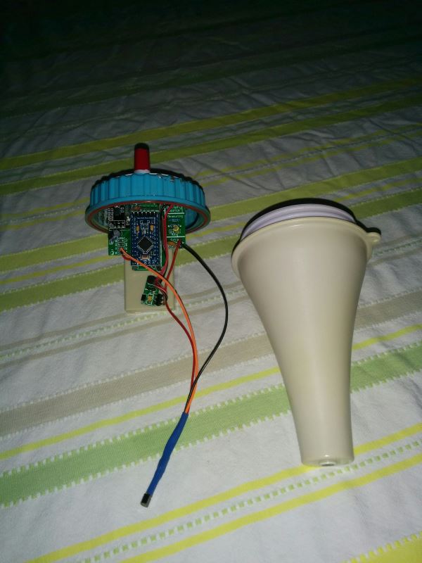
A node to indicate correct parking position to allow closing of garage door. * uses a pre built IR beam "door minder" to detect car position *MySensors V2 and using Adafruit neopixel library and bounce2 library * 
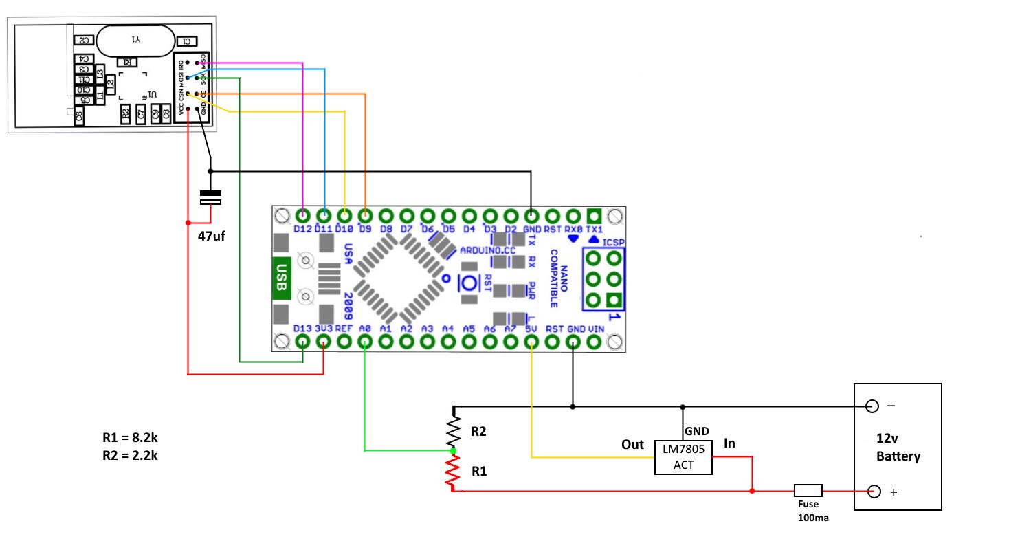
Connect N/O contacts of Infrared device between * pin 3 and GND. * * Connect a N/O reed switch between GND and pin 2 * * Connect RGB Led strip data terminal to pin 4 * */ // Enable debug prints to serial monitor #define MY_DEBUG // Enable and select radio type attached #define MY_RADIO_NRF24 #include "MySensors.h" #include <SPI.h> #include <Bounce2.h> #include <Adafruit_NeoPixel.h> #define NUM_LEDS 18 // How many leds are in the strip? change this to the number of LEDs in your strip #define PIN 4 // Data pin that led data will be written out over #define CHILD_ID 0 // door switch MySensors id number #define IR_PIN 3 // Arduino Digital I/O pin for infrared device #define DOOR_PIN 2 // pin garage door switch is connected to int marker = 0; // used to decide if LEDs are allowed to turn white int irValue ; // holder for ir state int doorValue ; // holder for garage door state int oldDoorValue=-1; //set to -1 to ensure current door switch status is sent at startup unsigned long startMillis = 0; // holder for the time when garage door first opens unsigned long millisNow = 0; // holder for the current time const long activeTime = 120000; // Time the sensor will stay active after garage door is opened in milliseconds. change this to suit your situation Bounce debouncerA = Bounce(); // Instantiate Bounce object 1.... iR switch Bounce debouncerB = Bounce(); // Instantiate Bounce object 2.... Garage Door switch MyMessage msg(CHILD_ID,V_TRIPPED); // Parameter 1 = number of pixels in strip // Parameter 2 = Arduino pin number (most are valid) // Parameter 3 = pixel type flags, add together as needed: // NEO_KHZ800 800 KHz bitstream (most NeoPixel products w/WS2812 LEDs) // NEO_KHZ400 400 KHz (classic 'v1' (not v2) FLORA pixels, WS2811 drivers) // NEO_GRB Pixels are wired for GRB bitstream (most NeoPixel products) // NEO_RGB Pixels are wired for RGB bitstream (v1 FLORA pixels, not v2) Adafruit_NeoPixel strip = Adafruit_NeoPixel(NUM_LEDS, PIN, NEO_GRB + NEO_KHZ800); void setup() { /* ----Setup the buttons as inputs and activate their internal pull-up resistor---- */ pinMode(IR_PIN,INPUT_PULLUP); //set pin as input and activate internal pull-up resistor pinMode(DOOR_PIN,INPUT_PULLUP); //set pin as input and activate internal pull-up resistor /* ---After setting up the buttons, setup debouncers---- */ debouncerA.attach(IR_PIN); debouncerA.interval(5); debouncerB.attach(DOOR_PIN); debouncerB.interval(5); strip.begin(); strip.show(); // Initialize all pixels to 'off' } void presentation() { // Send the sketch version information to the gateway and Controller sendSketchInfo("Park Sensor", "2.0"); // Register all sensors to gateway (they will be created as child devices) present(CHILD_ID, S_DOOR); // Register binary input sensor to gw } void loop() { updateSwitches(); // call function to check switches status millisNow = millis(); // get the current time if (millisNow - startMillis < activeTime){ // check to see if timeout has been reached if (doorValue == HIGH ) { // garage door is open if (irValue == LOW ) { // car is in ir beam ledChange(strip.Color(255, 0, 0)); // car is blocking ir beam,turn LEDs red } else{ ledChange(strip.Color(0, 255, 0)); // car is out of ir beam, turn LEDs green } } else{ if (marker == 1){ ledChange(strip.Color(127, 127, 127)); // door down but timer not finished. turn leds white for entry mode } } } else { // Timeout has been reached. Turn off LEDs if (marker == 1){ // check marker to only turn off if needed ledChange(strip.Color(0, 0, 0)); // turn off leds (black) marker = 0; } } } /* --------------start of functions-------------- */ /* --Update the switches status, send door state change if required -- */ void updateSwitches (){ debouncerA.update(); // IR switch debouncerB.update(); // Door switch irValue = debouncerA.read(); // get the state of the IR switch doorValue = debouncerB.read(); // get the state of the Door switch if (doorValue != oldDoorValue) { // Check if digital input has changed and send in new value if it has send(msg.set(doorValue==HIGH ? 1 : 0)); // Send in the new value if (doorValue == HIGH){ // door is open startMillis = millis(); // store start time of door opening for timeout check marker = 1; } oldDoorValue = doorValue; } } /* ----------function to change LED color------------*/ void ledChange(uint32_t c) { for(uint16_t i=0; i<strip.numPixels(); i++) { strip.setPixelColor(i, c); } strip.show(); }
    • Boots33

      12v Solar battery monitor
      My Project • • Boots33  

      59
      7
      Votes
      59
      Posts
      34364
      Views

      nurul amira

      @Boots33 thank you for your time to reply me .
    • Boots33

      S_MULTIMETER Help
      Troubleshooting • • Boots33  

      5
      0
      Votes
      5
      Posts
      2279
      Views

      siklosi

      Im also having problems with domoticz and negative values. Im reporting value and want to see increase or decrease. And negative values are represented as long int value -1 (I think).