@nurul-amira Yes that should all work fine. That circuit has been running 24/7 for around 4 years now without any issues.
Posts made by Boots33
-
RE: 12v Solar battery monitor
-
RE: How to properly handle variable requests
@tante-ju
Sorry for the late reply, I have been away for a few days with work.While I am sure there will be more than one way to achieve your goal I have given a brief outline of the way i did it below.
If all you want to do is request data from another node it should not need any more steps than @Sasquatch has listed above.
Lets say we have node A with an id of 1
we also have node B with an id of 2 and it has a binary sensor with a child id of 3Node A wants to know the the status of the binary sensor on node B
So in your code on node A you will issue the request to query child id 3 on node 2request( 3, V_STATUS, 2);
The gateway will rout this directly to node B where you will need to have code to deal with the request in the receive(); function. In it's simplest form you could have something like this below.
void receive(const MyMessage &message) { if (message.type == V_STATUS) { if (message.getCommand() == C_REQ){ // message is request // put code here to be executed when the message is from a request // most likely you will call a function that will get the requested // data and return it to node A. If you are expecting requests for more than 1 // sensor you can use message.sensor to test which sensor the request is for } else { // message is from gateway,process the message as per normal // put code here to be executed when the message is from gateway } } }
in the scenario above node B only expects requests from node A or commands from the gateway so it is easy to check what has arrived. If the message is a request we can execute code to get the required data and send it back. if it is a command (C_SET) from the gateway then it will fall through to the else part of the statement and be available as per normal.
To send back the Data you will need to use a node to node message.
this can be done on the fly, the format is shown below/* Node to Node message format. * * * * * * : Id of sending : message : Destination : Destination : Payload * * : sensor : Type : sensor Id : Node Id : */ send(MyMessage(sendingSensorId, V_STATUS).setSensor(sensorId).setDestination(nodeId).set(true)); //send message to desitination node
So using our example you would have. (As we are not trying to actually switch any sensors on node A we can leave out the setSensor() part of the message)
send(MyMessage(3, V_STATUS).setDestination(1).set(true));
Being a binary sensor the payload would be set to either true or false.
Now we have sent the data all that is left to do is catch it in the recieve part of node A. One way to do this is simply to test for where the message has come from, if it is from the gateway (node 0) or in our case node 2.
void receive(const MyMessage &message) { if (message.type == V_STATUS) { if (message.sender == 0) { // check if message is from gateway (node 0) // put code here for normal gateway messages } else { // message is not from gateway so check to see if it is from node B if (message.sender == 2 ){ Put code here to deal with returning request } } } }
-
RE: How to properly handle variable requests
sorry @tante-ju I am not quite getting what you are trying to achieve. Are you trying to request data directly from one node to the other of from a node to the controller.
-
RE: How to properly handle variable requests
If you are making a request to the controller it will return the required data for you to use, you will then need to have code on the requesting node to handle this return.
If you are making a node to node request you will need to manually handle both the incoming request on the target node and then use node to node communication to the return of the required data to the node that requested the data. Then on the node that sent the request you will need to have code to separate this return from normal controller commands.
In MySensors you can use message.sender to determine where the message came from and message.getCommand to see if the message is a request or command etc.
Have a look at these three posts to see what these look like in use and also how to format a node to node message.
https://forum.mysensors.org/topic/6422/display-node-how-to-set-up/20
https://forum.mysensors.org/topic/6948/synchronising-light-switch
https://forum.mysensors.org/topic/6542/outdoors-touch-switch-light-controller?_=1596330659286
-
RE: House renovation, how to a good electrical system oriented to MySensors?
@alowhum There will be a wealth of information out there on the net and probably also at your local library. look for resources about remote cabin power systems and also even the larger 5th wheeler type caravan systems will be helpful reading. You will also need to check your local building codes to see if there are any rules to be adhered to.
When we built our house (about 15 years ago, long before i discovered MySensors we ran a low voltage backbone cable throughout the house. From this backbone we ran smaller cable drops to every room in the house. Many of these are still not in use but as others have said the cost of running wires is relatively cheap when you are building. Of course we still have mains power as well and use the low voltage system to compliment this.
In those initial years the 12v system was used primarily for lighting systems such as night lights etc. As time progressed we installed 12v outlets in the bedrooms and these now are used to power bed/reading lamps. The small 12v downlights have also proved to be very easy to convert over as well. These were initially halogen bulbs but now there is a good range 12v LED replacements for just about any type of socket. Once I discovered MySensors and home automation then the 12v system became even more useful now powering several nodes and even the gateway.
Right from the start we ran our system from a battery with solar charging and in 15 years it has never let us down. Voltage drop will always be a thing to watch, but with LED's low power draw and as you have surmised the ability of arduinos to run well below 12v it will usually be of little practical concern. Unless of course you are thinking of running more than lights and nodes.
-
RE: Two MySensor gateways to the same Home Assistant
@jocke4u yes that is correct, both gateways will also need to be using different channels as well.
-
RE: Ds18b20/ nodemcu fluctuations in temp
@mjdula
The 85 reading is actually an error message used by the ds18b20 to indicate it has not had time to complete the processing of the reading. Most commonly this is only seen when the node first boots up and can be ignored or fixed by adding a small delay. You will find a lot of information on this if you do a google search. I have never experienced it myself but from other posts on the net it seems power supply problems and long cable runs to the sensor can also cause the error. Some have also had success by using a different resistor value. Note you only need one resistor fitted near your nodemcu not a resistor at each ds18b20.
If the 85 reading is well outside your expected reading you could just filter out any readings over 84 as well. -
RE: Newbie question about how the mysensors gateway connects to controller
yes you are correct, the serial gateway will connect to your controllers (Hassio) serial port and the Ethernet gateway will connect over your wired network connection. Both will work well, i guess the Ethernet approach gives you the flexibility of having the gateway away from the controller if needed.
In my setup I have two gateways, both are built on NodeMCU boards and connect via wifi. they have proven very reliable as well.
-
RE: (Solved) S_Multimeter in HomeAssistant
@Joost great news! always a good feeling when you find a solution to a pesky problem
-
RE: getting data from sensor to sensor
@Robert-Krรณl Yes that is certainly possible, Have a look at requesting data on the api page. You can request data from any node on your Mysensors network.
-
RE: (Solved) S_Multimeter in HomeAssistant
@Joost do you have hassio set to use V2.3 of the mysensors protocol in the configuration.yaml ?
-
RE: (Solved) S_Multimeter in HomeAssistant
Did you find a solution to your problem? I am using S_Multimeter in Hassio and measuring both voltage and current without problems so at least I can confirm that it should work.
Perhaps you could try entering the child details into your mysensors.json file directly then reboot and see if that helps.
should be something like this
"120": { "sensor_id": 120, "children": { "0": { "id": 0, "type": 30, "description": "Batterie", "values": { "38": "5.2" } } }, "type": 17, "sketch_name": "Voltmeter", "sketch_version": "1.0", "battery_level": 0, "protocol_version": "2.3.1", "heartbeat": 0 }
-
RE: Round water tank level sensor
@ritesh-t If you have not already found it you may also benefit from the thread by @zboblamont which can be found here. It addresses some issues of unstable readings that were occurring when the water in the tank was at a lower level.
-
RE: An ultrasonic measurement saga finally over...
@zboblamont I would be interested to see your final sketch if you don't mind posting it.
-
RE: An ultrasonic measurement saga finally over...
Well done @zboblamont great news to see you have had a win.
-
RE: 12v Solar battery monitor
@unfadingpyro Great to hear you got it all working. Always a good feeling when a project comes together
-
RE: relay statue doesn't change
1.5.4 is a few versions back now so it will help if you post the code you are using, even if it is the standard version. That will give us a starting point to work from.
Also what controller are you using. -
RE: 12v Solar battery monitor
Yes i can see your wiring now and no you are not likely to get any sort of reading with that circuit. You have the 712 wired in parallel with the charge wire, it needs to be in series instead. The load needs to be connected to the same side that the charge wire is on. So a quick re-draw of your circuit would look like this.
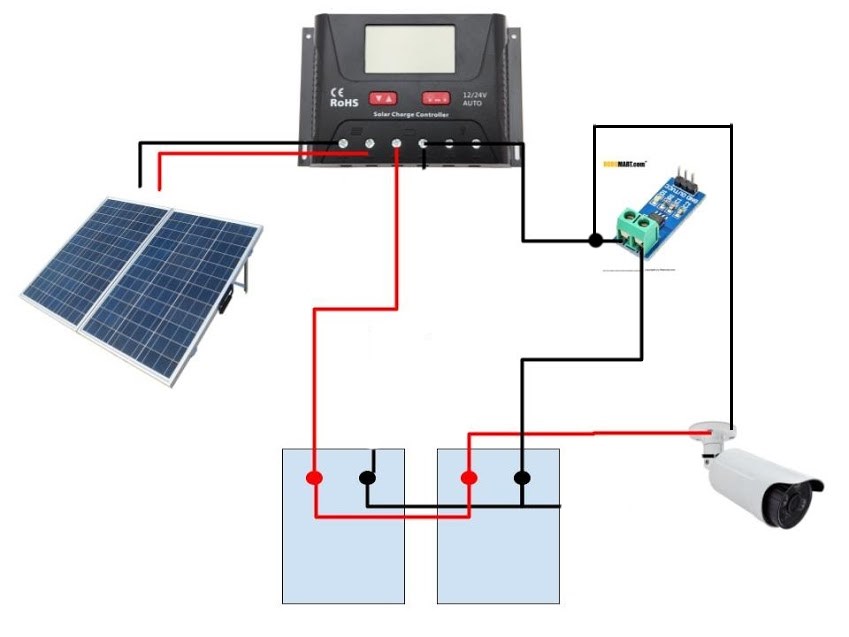
Don't forget to add a fuse at the battery positive.
The original drawing from earlier in this thread would also be ok
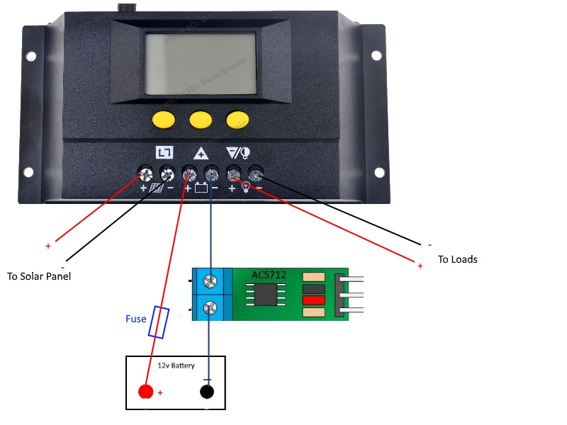
-
RE: relay statue doesn't change
Your only getting 0 sent for the relay so it certainly won't be changing status. Perhaps post the code you are using .
-
RE: Domoticz help using V_VAR1 and S_CUSTOM
@alexsh1 I ended up using the dust sensor type for both readings. In Domoticz it allows you to set the letters to be used after the number so was easy to just add km to the end.
The original post where using dust was discussed is here
-
RE: relay as a switch not as a button (domoticz)
@ago1980 It should work but as I said i have not tested it. You may still need to tweak it to suit your setup.
To add extra relays I usually just duplicate the code if it is only two relays but more than that you will probably want to use a loop and perhaps an array to assign the variables etc. You will also need to add some code to your void receive function to sort out which switch/relay the incoming message is for.
The RelayActuator sketch in the MySensors examples shows a way to add more than one relay.
You could also have a look at my AC power controller project for an idea of how to use a case statement in the receive function to filter the incoming messages.
-
RE: relay as a switch not as a button (domoticz)
@ago1980 said in relay as a switch not as a button (domoticz):
so if I use switches I should not have problems?
Other than the issues I have outlined in my post above the toggle switch will work just like the button.
The basic re-write of the original button with relay sketch so it will work with a toggle switch and no uplink to the gateway is shown below. Remember it does not try and keep in sync with the controller other than notifying it of a change by the switch.
As @dbemowsk has already said you should also try and find out why the node is losing its uplink to the gateway.Sketch untested but I think should be ok
/* Relay with toggle switch sketch modified to work with no uplink to gateway Toggle switch connected between pin3 and ground. */ #define MY_DEBUG // Enable debug prints to serial monitor #define MY_RADIO_NRF24 // Enable and select radio type attached #define MY_TRANSPORT_WAIT_READY_MS 5000 //set how long to wait for transport ready in milliseconds #include <MySensors.h> #include <Bounce2.h> #define RELAY_PIN 4 // Arduino Digital I/O pin number for relay #define SWITCH_PIN 3 // Arduino Digital I/O pin number for switch #define CHILD_ID 1 // Id of the sensor child #define RELAY_ON 1 #define RELAY_OFF 0 Bounce debouncer = Bounce(); int oldswitchState = 0; bool state = false; bool firstStart = true; MyMessage msg(CHILD_ID, V_STATUS); void setup(){ pinMode(SWITCH_PIN, INPUT_PULLUP); // Setup the button pin, Activate internal pull-up debouncer.attach(SWITCH_PIN); // After setting up the button, setup debouncer debouncer.interval(5); pinMode(RELAY_PIN, OUTPUT); // set relay pin in output mode digitalWrite(RELAY_PIN, RELAY_OFF); // Make sure relay is off when starting up } void presentation() { // Send the sketch version information to the gateway and Controller sendSketchInfo("Relay & Toggle", "1.0"); // Register all sensors to gw (they will be created as child devices) present(CHILD_ID, S_BINARY); } void loop(){ if (firstStart) { // this code is only run once at startup debouncer.update(); oldswitchState = debouncer.read(); // set oldswitchState to the current toggle switch state send(msg.set(false), false); // notify controller of current state no ack firstStart = false; // set firstStart flag false to prevent code from running again } debouncer.update(); int switchState = debouncer.read(); // Get the update value if (switchState != oldswitchState) { // check for new throw of toggle switch state = !state; // Toggle the state digitalWrite(RELAY_PIN, state ? RELAY_ON : RELAY_OFF); // switch the relay to the new state send(msg.set(state), false); // notify controller of current state no ack oldswitchState = switchState; } } /*-------------------start of functions--------------------------*/ void receive(const MyMessage &message) { if (message.type == V_STATUS) { // check to see if incoming message is for a switch state = message.getBool(); // get the new state digitalWrite(RELAY_PIN, state ? RELAY_ON : RELAY_OFF); // switch relay to new state /*---- Write some debug info----*/ Serial.print("Incoming change for sensor:"); Serial.print(message.sensor); Serial.print(", New status: "); Serial.println(message.getBool()); } }
-
RE: relay as a switch not as a button (domoticz)
@ago1980 said in relay as a switch not as a button (domoticz):
I mean if GATEWAY does not work for some problem the node does not work does not turn on light
The original sketch relies on an ack from the gateway to trigger the relay, so if the gateway is not available the relay state cannot be changed by the local switch or even the controller.
Under most circumstances it would be desirable to have the local switch function no matter what the state of the network is. To do this you will need to modify the sketch so it no longer relies on the ack to make the change.
In MySensors 2.1.1 by default a node will not boot through to the loop section of your sketch if it cannot find the gateway, so the first thing you need to do is force it to move on.
The line shown below will do just that. The number at the end is how long you want the node to wait for an uplink to be established before it will move on to the rest of your sketch. It is in milliseconds, so in the example below it will wait 5 seconds. This line needs to be inserted near the top of your sketch before the #include <MySensors.h> line.
#define MY_TRANSPORT_WAIT_READY_MS 5000
After adding that you will then need to change the sketch so it no longer relies on the ack to change the relay state. that is pretty straight forward and once done your relay will then be able to be switched by the local switch no mater what the uplink status is.
The next problem you will encounter is trying to keep your controller in sync with the local node. As you can now change the state of the relay without a connection to the controller it may loose its sync to the node. So you may find your controller thinks the relay is on when it is actually off. This is where it gets a little trickier so if it is important to you that the controller stays in sync you may need to experiment a bit to find what will give you the best results.
I have some examples of relay nodes that explore ways to switch locally and try to maintain sync with the controller.
The last sketch I posted there uses requestTime() to check to see if the controller is available and though there is a trade off in how quickly you can flick the switch back and forward it at least confirms that the controller is available. Other methods may only check for the gateways presence.Have a look you may find something of use.
Its a bit of an old post but some of these issues (using a toggle switch and making the switch always work) were also discussed in this post
-
RE: Imperial Units
@ryan-dick said in Imperial Units:
I believe the problem is this line:
> float temperature = static_cast<float>(static_cast<int>((getControllerConfig().isMetric?sensors.getTempCByIndex(i):sensors.getTempFByIndex(i)) * 10.)) / 10.;
You are right, that line is asking your controller as to whether you are using metric or imperial and then giving the answer in the appropriate type.
I do not use openhab but it should have a place in settings to select the correct units to be used. If you already have imperial selected in openhab it may be that openhab does not support getControllerConfig() so is not returning the correct result.
If you only ever want the results to be in imperial you could just modify the line so it no longer asks for the config from the controller and just uses imperial. I have not tried it but something like this should work
float temperature = static_cast<float>(static_cast<int>((sensors.getTempFByIndex(i)) * 10.)) / 10.;
-
RE: which sensor and msg type for switch/dimmer node (sender only)?
@andrew At the moment any data enforcing you require will need to be coded in your sketch and as I have said there are ways to determine the data type required.
I am not sure as to why it is not present in the MySensors library, it may be worthwhile to start another thread on this and see what other information you can get.
-
RE: which sensor and msg type for switch/dimmer node (sender only)?
@andrew said in which sensor and msg type for switch/dimmer node (sender only)?:
by browsing the API documentation I did not find mapping details between the message type enums and their corresponding data representing format.
so, from where should I know that e.g. V_PERCENTAGE messages needs uint8_t and not anything else? as I see it is possible to send any data format for any message type.I have not seen a list , there was a post that asked the same thing but it did not seem to go anywhere.
if I have to handle the messages between my nodes then it is not that problematic, but if it has to be forwarded to the controller then it would be nice to have it standardized.
If I am unsure I usually just get the data type from the serial data during construction/testing. Just look at the send data, the payload type (pt) will be shown there. The send message below for a binary device shows pt=1 which is a byte.
TSF:MSG:SEND,233-233-0-0,s=1,c=1,t=2,pt=1,l=1,sg=0,ft=0,st=OK:1
The definitions for pt are
P_STRING = 0, P_BYTE = 1, P_INT16 = 2, P_UINT16 = 3, P_LONG32 = 4,
P_ULONG32 = 5, P_CUSTOM = 6, P_FLOAT32 = 7Be mindful that the receive message is different:
TSF:MSG:READ,0-0-233,s=1,c=1,t=2,pt=0,l=1,sg=0:0
You can see the message sent from the controller for the same switch arrives as pt=0 which is a string.
You can also use the handy Log Parser to decode the serial data. here is the readout for the previous two lines.
-
RE: which sensor and msg type for switch/dimmer node (sender only)?
You will be able to send node to node without the controller but I do not think node to node will work without the gateway, on 2.1.1 at least. There have been posts on this issue before, not sure if the development branch has moved forward on this.
Node to node communication fails if gateway is not reachable
(Almost) Controller-Less MySensors switch/light network
The other problem you will face will be trying to keep your remote switch node in sync with the led control node. This will be easy enough to do when the network is fully working but becomes harder if one or more of the nodes does not receive a message when it is sent.
Some other posts that may be of interest, showing node to node and requesting node status.
AC Power controller with node to node remotes
Outdoors Touch Switch light controller
The only way I can think of that will absolutely guarantee control of the lights at all times is to have the switching mechanism directly wired to the lamp controller. Like in this example
-
RE: which sensor and msg type for switch/dimmer node (sender only)?
I think the node that actually controls the leds would need to be using S_DIMMER but you probably would only need to use S_BINARY for the wireless remote to control the feedback leds.
You could then just send node to node messages to the dimmer module for on/off or dimmer level and the dimmer module would send back the status for your feedback leds.
-
RE: Poolside Music Player
@dbemowsk I can't even imagine those sort of temps! Don't think my freezer can go that low
-
RE: Poolside Music Player
Ha ha... no white Christmas in the land down under @dbemowsk Pool temp is pretty stable at around 30c at the moment so that should thaw you out. At the moment we spend our weekends wakeboarding at the lake or
Going to the Beach
@Nca78 is right though, I have to drive over 1500km if I want to see some snow and there is only snow there in winter. Temps have already been up to 37c here so it does get a bit toasty at times!
-
Poolside Music Player
I built a pool thermometer to keep track of the water temperature but the node could not reliably connect to the closest repeater.
The repeater node was not that far away so I think maybe the closeness of the water and perhaps the pool fence were causing some problems. The easiest solution was to just deploy another repeater node to bridge the gap.I didn't wan't to have a node just for repeating the temp data so decided to make use of it as a music player for the pool area as well.
To keep it simple I settled on a cheap Bluetooth enabled amplifier module and a couple of marine speakers, The node just turns power on and off to the amp and I can control the volume and stream music from my phone via the bluetooth connection.
For convenience I have set up a button on my Touch switch so I can turn the amp on/off when walking down to the pool area.
The circuit is just a simple single switch type node to control power to the amp.
The sketch is a standard relay control with a timer to shut down the amp after 3hrs. We are seldom in the pool for longer than that and wanted a way to ensure the amp is not left switched on by accident.
/** *Node to control pool music player * *Auto turns off after preset time * */ // Enable debug prints to serial monitor #define MY_DEBUG // Enable and select radio type attached #define MY_RADIO_NRF24 #define MY_RF24_CHANNEL 84 #define MY_REPEATER_FEATURE #include <MySensors.h> #define PLAYER_PIN 6 // Arduino pin number for Player power control #define PLAYER_ID 1 // Id of the player control child unsigned long millisNow = 0; // holder for the current time unsigned long startMillisA = 0; unsigned long activeTimeA = 180; // how long the player will stay on, in minutes const int switchOn = 1; const int switchOff = 0; int timerMarkerA = 0; // Used to tell if timer A is active bool stateA = false; // State holder for player MyMessage msgA(PLAYER_ID, V_STATUS); void setup() { pinMode(PLAYER_PIN, OUTPUT); // set player pin in output mode digitalWrite(PLAYER_PIN, switchOff); // Make sure player is off when starting up } void presentation() { // Send the sketch version information to the gateway and Controller sendSketchInfo("Pool Player", "1.3"); present(PLAYER_ID, S_BINARY,"Pool Player"); } void loop() { poolTimer(); } void receive(const MyMessage &message){ if (message.type==V_STATUS) { // check that message is for binary switch if (message.sender == 0) { // check if message is from gateway (node 0) stateA = message.getBool(); digitalWrite(PLAYER_PIN, stateA ? switchOn : switchOff); } else { // message is not from gateway so must be from a remote stateA = !stateA; // toggle player state digitalWrite(PLAYER_PIN, stateA ? switchOn : switchOff); wait (10); send( msgA.set(stateA),false) ; // Notify controller of change } } } void poolTimer() { millisNow = millis(); // get the current time if (digitalRead(PLAYER_PIN) == switchOn && timerMarkerA == 0 ) { //Check relayPinA status and start timer event if relay is on. timerMarkerA = 1; startMillisA = millisNow; } if (timerMarkerA == 1 && (millisNow - startMillisA) > (activeTimeA*60000)) { // check to see if timeout has been reached digitalWrite(PLAYER_PIN, switchOff); // turn off player send(msgA.set(false),false ); // send message to controller so it knows the player is now off timerMarkerA = 0; //reset marker stateA = false; } if (digitalRead(PLAYER_PIN) == switchOff && timerMarkerA == 1 ) { //if player has been turned off by user, cancel timer event timerMarkerA = 0; Serial.println("timer A cancelled" ); } }
The node was constructed on a small prototype board with the nrf mounted well clear at the top.
Here it is shown with the amp and speakers during testing.
The node was housed in a section of 90mm water pipe.
The speakers were fitted to an existing seat/storage area. Just a bit of tidying up of the wiring etc to do.
-
RE: Getting values from outside my nodes
@crankycoder said in Getting values from outside my nodes:
that part I was able to figure out. Was hoping someone had some working examples on how to get the controller to monitor for those requests and answer back.
I think it is as @gohan has said, if the controller supports request it will be handled automatically and returned to the asking node.
You have to have code in your void receive(const MyMessage &message) to do something with the returning request. In Domoticz I have found it can take several hundred milliseconds for the request to return so you may have to wait before you get a result.
Nodes can also request data directly from other nodes but you need to handle the request and return manually in that case as the controller will not be involved.
You may find the info in this post of some use.
I have also used request in this project where you can see the delay needed before reading the return. -
RE: Synchronising Light switch
@pepson said in Synchronising Light switch:
Status is not refreshed only in one situation. When i only reboote controller with gateway and under reboote i change status NODE. After run controller and gateway status is not refresh and show not correct.
Sorry I do not understand what start up scenario you are describing here. Can you post details of the exact steps needed to replicate this problem.
Please share me this sketch if you can for 2xrelays ? And also option with send temperature from Dallas DS18b20 ?
I do not have any sketches that include switches & temperature sensors, there are however some posts already on combining relays and temp senders. You should do a search to locate them or perhaps start a new thread about that.
One question... How change time betwen change relay on and off. Now i must wait about 2-4 secund before try change status on off by button. Can i change this time ?
The relay should change from on/off instantly from the local switch or from the controller.
The delay in being able to continuously flick the switch between on and off will most likely be caused by the delay required to receive the time return.
As I said in an earlier post : In testing the return from request usually arrived within 800 milliseconds so returnWait could also be reduced from 1500ms if it was a concern.If you reduce it too far the switch sync will once again become unreliable. This is the trade off for a sync switch
Why do you need to switch your lights every 2 seconds?
-
RE: Synchronising Light switch
Just a couple of other ideas on this subject to share
This sketch is a small modification on the original to allow for the use of a toggle type switch instead of the push button
/* Relay with toggle switch sketch modified to work with no uplink to gateway and try to maintain sync to controller Toggle switch connected between pin3 and ground. */ #define MY_DEBUG // Enable debug prints to serial monitor #define MY_RADIO_NRF24 // Enable and select radio type attached #define MY_TRANSPORT_WAIT_READY_MS 5000 //set how long to wait for transport ready in milliseconds #include <MySensors.h> #include <Bounce2.h> #define RELAY_PIN 4 // Arduino Digital I/O pin number for relay #define SWITCH_PIN 3 // Arduino Digital I/O pin number for switch #define CHILD_ID 1 // Id of the sensor child #define RELAY_ON 1 #define RELAY_OFF 0 Bounce debouncer = Bounce(); int oldValue = 0; bool uplinkAvailable = true; bool state = false; bool requestState; bool firstStart = true; unsigned long uplinkCheckTime ; // holder for uplink checks unsigned long uplinkCheckPeriod = 30*1000; // time between checks for uplink in milliseconds unsigned long returnWait = 1500; // how long to wait for return from controller in milliseconds MyMessage msg(CHILD_ID, V_STATUS); void setup(){ pinMode(SWITCH_PIN, INPUT_PULLUP); // Setup the button pin, Activate internal pull-up debouncer.attach(SWITCH_PIN); // After setting up the button, setup debouncer debouncer.interval(5); pinMode(RELAY_PIN, OUTPUT); // set relay pin in output mode digitalWrite(RELAY_PIN, RELAY_OFF); // Make sure relay is off when starting up } void presentation() { // Send the sketch version information to the gateway and Controller sendSketchInfo("Relay & Toggle", "1.0"); // Register all sensors to gw (they will be created as child devices) present(CHILD_ID, S_BINARY); } void loop(){ if (firstStart) { // this code is only run once at startup Serial.println("First run started"); if (request( CHILD_ID, V_STATUS)) { // request the current state of the switch on the controller and check that an ack was received Serial.println("uplink available"); wait (returnWait); //wait needed to allow request to return from controller Serial.print("controller state --- "); Serial.println(requestState); if (requestState != state) { // check that controller is corectly showing the current relay state send(msg.set(state), false); // notify controller of current state } } else { Serial.println("uplink not available"); uplinkAvailable = false; // no uplink established uplinkCheckTime = millis(); } firstStart = false; // set firstStart flag false to prevent code from running again } debouncer.update(); int value = debouncer.read(); // Get the update value if (value != oldValue) { // check for new throw of toggle switch state = !state; // Toggle the state digitalWrite(RELAY_PIN, state ? RELAY_ON : RELAY_OFF); // switch the relay to the new state if (!send(msg.set(state), true)) { //Attempt to notify controller of changed state Serial.println("uplink not available"); uplinkAvailable = false; // no uplink available uplinkCheckTime = millis(); } oldValue = value; } if (!uplinkAvailable && (millis() - uplinkCheckTime > uplinkCheckPeriod) ) { // test to see if function should be called uplinkCheck(); // call uplink checking function } } /*-------------------start of functions--------------------------*/ void receive(const MyMessage &message) { if (message.type == V_STATUS) { // check to see if incoming message is for a switch switch (message.getCommand()) { // message.getCommand will give us the command type of the incomming message case C_SET: //message is a set command from controller to update relay state state = message.getBool(); // get the new state digitalWrite(RELAY_PIN, state ? RELAY_ON : RELAY_OFF); // switch relay to new state uplinkAvailable = true; // uplink established /*---- Write some debug info----*/ Serial.print("Incoming change for sensor:"); Serial.print(message.sensor); Serial.print(", New status: "); Serial.println(message.getBool()); break; case C_REQ: // message is a returning request from controller requestState = message.getBool(); // update requestState with returning state break; } } } void uplinkCheck() { if (request( CHILD_ID, V_STATUS)) { // request the current state of the switch on the controller and check that the request was succsessful Serial.println("uplink re-established"); wait (returnWait); //wait needed to allow request to return from controller if (requestState != state) { // check that controller is corectly showing the current relay state send(msg.set(state), false); // notify controller of current state no ack uplinkAvailable = true; // uplink established } } uplinkCheckTime = millis(); // reset the checktime Serial.println("uplinkchecktime reset"); }
This next sketch is for a push button once again but this time it is using requestTime() to try and determine if the controller is available. While all uplink checks are only made to the gateway, by checking for the time returned from the controller it is possible to use this to test for the controllers presence. I have not tested this code extensively but it does appear to work ok within the original design goals.
/* Relay with button sketch modified to work with no uplink to gateway and try to maintain sync to controller */ #define MY_DEBUG // Enable debug prints to serial monitor #define MY_RADIO_NRF24 // Enable and select radio type attached //#define MY_RF24_CHANNEL 84 //#define MY_NODE_ID 203 #define MY_TRANSPORT_WAIT_READY_MS 5000 //set how long to wait for transport ready in milliseconds #include <MySensors.h> #include <Bounce2.h> #define RELAY_PIN 4 // Arduino Digital I/O pin number for relay #define BUTTON_PIN 3 // Arduino Digital I/O pin number for button #define CHILD_ID 1 // Id of the sensor child #define RELAY_ON 1 #define RELAY_OFF 0 Bounce debouncer = Bounce(); int oldValue = 0; bool uplinkAvailable = true; bool state = false; bool requestState; bool firstStart = true; unsigned long uplinkCheckTime ; // holder for uplink checks unsigned long uplinkCheckPeriod = 30*1000; // time between checks for uplink in milliseconds unsigned long returnWait = 1500; // how long to wait for return from controller in milliseconds.. adjust as needed unsigned long oldTime = 0; unsigned long newTime = 0; MyMessage msg(CHILD_ID, V_STATUS); void setup(){ pinMode(BUTTON_PIN, INPUT_PULLUP); // Setup the button pin, Activate internal pull-up debouncer.attach(BUTTON_PIN); // After setting up the button, setup debouncer debouncer.interval(5); pinMode(RELAY_PIN, OUTPUT); // set relay pin in output mode digitalWrite(RELAY_PIN, RELAY_OFF); // Make sure relay is off when starting up } void presentation() { // Send the sketch version information to the gateway and Controller sendSketchInfo("Relay & Button test", "1.1"); // Register all sensors to gw (they will be created as child devices) present(CHILD_ID, S_BINARY); } void loop(){ if (firstStart) { // this code is only run once at startup Serial.println("First run started"); requestTime(); // get time from controller wait (returnWait); // delay to allow time to return if (oldTime == 0){ // check to see if there was a return from the time request Serial.println("uplink not available"); uplinkAvailable = false; // no uplink established uplinkCheckTime = millis(); } else{ Serial.println("uplink available"); request( CHILD_ID, V_STATUS); // get status of switch on controller wait (returnWait); //wait needed to allow request to return from controller Serial.print("controller state --- "); Serial.println(requestState); if (requestState != state) { // check that controller is corectly showing the current relay state send(msg.set(state), false); // notify controller of current state } } firstStart = false; // set firstStart flag false to prevent code from running again } debouncer.update(); int value = debouncer.read(); // Get the update value if (value != oldValue && value == 0) { // check for new button push state = !state; // Toggle the state digitalWrite(RELAY_PIN, state ? RELAY_ON : RELAY_OFF); // switch the relay to the new state requestTime(); wait (returnWait); // delay to allow time to return if (oldTime != newTime){ // if times are different then uplink is available send(msg.set(state), false); oldTime = newTime; } else{ // if times are the same no uplink is available Serial.println("uplink not available"); uplinkAvailable = false; // no uplink available, set flag false uplinkCheckTime = millis(); // start the timer from now } } oldValue = value; if (!uplinkAvailable && (millis() - uplinkCheckTime > uplinkCheckPeriod) ) { // test to see if function should be called uplinkCheck(); // call uplink checking function } } /*-------------------start of functions--------------------------*/ void receive(const MyMessage &message) { if (message.type == V_STATUS) { // check to see if incoming message is for a switch switch (message.getCommand()) { // message.getCommand will give us the command type of the incomming message case C_SET: //message is a set command from controller to update relay state state = message.getBool(); // get the new state digitalWrite(RELAY_PIN, state ? RELAY_ON : RELAY_OFF); // switch relay to new state uplinkAvailable = true; // uplink established /*---- Write some debug info----*/ Serial.print("Incoming change for sensor:"); Serial.print(message.sensor); Serial.print(", New status: "); Serial.println(message.getBool()); break; case C_REQ: // message is a returning request from controller requestState = message.getBool(); // update requestState with returning state break; } } } void uplinkCheck() { requestTime(); wait (returnWait); // wait for time return.. this may need to be varied for your system if (oldTime != newTime){ Serial.println("uplink re-established"); request( CHILD_ID, V_STATUS); wait (returnWait); //wait needed to allow request to return from controller if (requestState != state) { // check that controller is corectly showing the current relay state send(msg.set(state), false); // notify controller of current state no ack uplinkAvailable = true; // uplink established oldTime = newTime; } } uplinkCheckTime = millis(); // reset the checktime Serial.println("uplinkchecktime reset"); } void receiveTime(unsigned long time) { if (firstStart){ oldTime = time; newTime = time; } else{ newTime = time; } Serial.print("time received---- " ); Serial.println(time); }
-
RE: Multi Button Relay Sketch
@pepson said in Multi Button Relay Sketch:
because NODE with relay start faster than DOmoticz with Gateway.
One solution could be to add a delay to your node and gateway sketches. This could just be run once as the node/gateway boots up thus giving Domoticz time to boot.
Also when i disable power from Domoticz with ENABLE RELAY . but NODe has still power and change relay to DISABLE and then again POWER ON Domoticz. After run Domoticz not show actual status my Relay because GATWAY was disable >when i change status relay.
As I have said earlier all MySensors 2.1 checks for uplink available are only checking for a connection to the gateway not all the way to the controller. So you can turn the controller on and off as often as you like and the node will not know it is not there. As long as the gateway is present the node will show the uplink as available.
Explaine me more please for what is in your sketch SYNCHRONISING ? What does it give us?
My original syncing switch sketch that i pointed you to above will work for most normal situations where the controller and gateway are on the same power supply. If you add the delay I have mentioned to your Gateway/node then that will allow the controller to boot first when returning from a power outage.
When you are turning off the controller by itself I do not think that is a true real world test, if the gateway and controller share the same power supply then this is not likely to happen.
In any case you may need to implement some form of code on Dometicz to push the occurrence of a controller reboot to your nodes. The nodes will not detect a missing controller unless your nodes are constantly pinging the controller to see if it is there.
I do have the other sketch using a time request to check for the presence of the controller, I will post that code in my Synchronising Light switch thread for you to try.
-
RE: Multi Button Relay Sketch
@pepson said in Multi Button Relay Sketch:
I try sketch from your link but i test and the same issu.
I enable relay, then disable GATEWAY MySensors on DOmoticz and then change status relay to DISABLE by button. Then enable Gateway on Domoticz and still in domoticz show that relay is ENABLED. Not update status that i manual DISABLE relay by button.As far as I know there is no direct way to test for a connection all the way to the controller in MySensors 2.1.
My sketch for the synchronising switch uses the presence of the gateway as the test, this has been adequate for my needs. My controller and gateway are both powered from the same place so they both go down if power is lost.
I have found Domoticz very stable and have not had any issues with it at all so am wondering why Dometicz seems to be giving you problems. is it powered from a different supply to your gateway?
I do have another sketch that uses requestTime as a way of checking for the controller that may be of use to you. it needs a little cleaning up first, so will have a look at it when i get a chance and post it for you to try.
-
RE: Round water tank level sensor
@lawrence-helm The tank that I am monitoring is used primarily for garden watering and topping up the pool, so it does not really have a regular sort of use. We also live in an area of frequent rainfall so the tank can stay at 100% for weeks on end.
I can see that your idea would be a good addition to the sketch if the tank was to be used for general house duties where more frequent use would likely give a more meaningful result.
-
RE: Multi Button Relay Sketch
@pepson have a look at this Synchronising Light switch
-
RE: Swimming Pool Thermometer
I now have a repeater in range of the pool area so the temperature node is finally transmitting data back to Domoticz.
Here it is lounging about the pool, it sits nice and level and is still afloat after a couple of days in the water.
Pool temp is is nice and comfy at the moment
-
RE: Dimmable LED help needed !
@plantex said in Dimmable LED help needed !:
Hi
Instead of trying to solve the problem for 1 Led stripe I've decided to go with 6 pcs now - basically I'm gonna need this anyway to do my "high-end" stairs.So what I've done is I've combined Your sketch with some other especially the part with few led's declaration
I do not think it is a good idea to add complexity to an already non working sketch. You should concentrate on getting the single sketch to work first and then add more later.
I am thinking maybe I can sacrifice "save the last dimmer value" - just to get this leds working normal
You should also have a clear idea of how you want the lights to work before you proceed any further. It will certainly make a difference to the coding.
P.S
I can paste my debug but there is so many problems I dont even know which bahavior case ( LED 4 or LED 6 or LED1 etc..) I should paste from my debugThis is why you should keep it simple and get that to work first
-
RE: Dimmable LED help needed !
I think the 666 is coming from the initial request made in setup part of the sketch. Perhaps because it is made before the presentation of the node we are getting invalid data?
I see that in the original part of the sketch that I commented out there is code to constrain the percentage value between 0 and 100 . So maybe this is a known issue. We may need to move the request to the main loop instead.In any case we can make a couple of changes to see if it is the cause of the multi switching.
at the start of the sketch change
int dimmerSetting = 0 ;
to
int dimmerSetting = 100 ;Then comment out the request call in the setup section.
//request( 0, V_PERCENTAGE );
Now when the node first boots it should turn the lights on to 100% when the switch is used. However once you have set the dimmer it will use that percentage instead.
I know this is not how you want the final node to work, this is just to see if the request is what is causing the trouble.
-
RE: Dimmable LED help needed !
@plantex said in Dimmable LED help needed !:
Hi
I'm testing Dimmable LED Actuator --> https://www.mysensors.org/build/dimmer
Everything seems to work with Domoticz except one thing - It doesn't remember last dimming value (This is a feature I really need).
After switching the light off and back on , no matter what value was before it goes everytime to 100%Yes that is how that sketch was written to work. You can change it to work the way you want. There are several ways you could attack the problem, you could save the dimmer level to eeprom or perhaps request the dimmer level from the controller.
Which part is responsible for sending the information to LED_PIN 3 ? I tried to >define LED pin3, also fade delay etc... to the below sketch - no luck.
It is the line
analogWrite( LED_PIN, (int)(currentLevel / 100. * 255) );
But as you have already found the line below is responsible for turning on the lights at 100% when the switch is used
requestedLevel *= ( message.type == V_LIGHT ? 100 : 1 );
Does it matter if the variables are V_LIGHT and V_DIMMER if the type is >S_DIMMER ? (both sketches) Shouldn't it be V_STATUS and V_PERCENTAGE ?
While they are interchangeable and working for the present V_LIGHT and V_DIMMER have both been deprecated and may not work in future releases of MySensors. You should use V_STATUS and V_PERCENTAGE instead.
To get you started I have made a quick change to the the code from the build dimmer page. I have not tested it so give it a try and see if it does what you want.
/** * The MySensors Arduino library handles the wireless radio link and protocol * between your home built sensors/actuators and HA controller of choice. * The sensors forms a self healing radio network with optional repeaters. Each * repeater and gateway builds a routing tables in EEPROM which keeps track of the * network topology allowing messages to be routed to nodes. * * Created by Henrik Ekblad <henrik.ekblad@mysensors.org> * Copyright (C) 2013-2015 Sensnology AB * Full contributor list: https://github.com/mysensors/Arduino/graphs/contributors * * Documentation: http://www.mysensors.org * Support Forum: http://forum.mysensors.org * * This program is free software; you can redistribute it and/or * modify it under the terms of the GNU General Public License * version 2 as published by the Free Software Foundation. * ******************************* * * REVISION HISTORY * Version 1.0 - February 15, 2014 - Bruce Lacey * Version 1.1 - August 13, 2014 - Converted to 1.4 (hek) * * DESCRIPTION * This sketch provides a Dimmable LED Light using PWM and based Henrik Ekblad * <henrik.ekblad@gmail.com> Vera Arduino Sensor project. * Developed by Bruce Lacey, inspired by Hek's MySensor's example sketches. * * The circuit uses a MOSFET for Pulse-Wave-Modulation to dim the attached LED or LED strip. * The MOSFET Gate pin is connected to Arduino pin 3 (LED_PIN), the MOSFET Drain pin is connected * to the LED negative terminal and the MOSFET Source pin is connected to ground. * * This sketch is extensible to support more than one MOSFET/PWM dimmer per circuit. * http://www.mysensors.org/build/dimmer */ // Enable debug prints to serial monitor #define MY_DEBUG // Enable and select radio type attached #define MY_RADIO_NRF24 //#define MY_RADIO_RFM69 #include <MySensors.h> #define SN "DimmableLED" #define SV "1.1" #define LED_PIN 3 // Arduino pin attached to MOSFET Gate pin #define FADE_DELAY 10 // Delay in ms for each percentage fade up/down (10ms = 1s full-range dim) static int16_t currentLevel = 0; // Current dim level... int dimmerSetting = 0 ; MyMessage dimmerMsg(0, V_PERCENTAGE); MyMessage lightMsg(0, V_STATUS); /*** * Dimmable LED initialization method */ void setup() { // Pull the gateway's current dim level - restore light level upon sendor node power-up request( 0, V_PERCENTAGE ); } void presentation() { // Register the LED Dimmable Light with the gateway present( 0, S_DIMMER ); sendSketchInfo(SN, SV); } /*** * Dimmable LED main processing loop */ void loop() { } /* void receive(const MyMessage &message) { if (message.type == V_LIGHT || message.type == V_DIMMER) { // Retrieve the power or dim level from the incoming request message int requestedLevel = atoi( message.data ); // Adjust incoming level if this is a V_LIGHT variable update [0 == off, 1 == on] requestedLevel *= ( message.type == V_LIGHT ? 100 : 1 ); // Clip incoming level to valid range of 0 to 100 requestedLevel = requestedLevel > 100 ? 100 : requestedLevel; requestedLevel = requestedLevel < 0 ? 0 : requestedLevel; Serial.print( "Changing level to " ); Serial.print( requestedLevel ); Serial.print( ", from " ); Serial.println( currentLevel ); fadeToLevel( requestedLevel ); // Inform the gateway of the current DimmableLED's SwitchPower1 and LoadLevelStatus value... send(lightMsg.set(currentLevel > 0)); // hek comment: Is this really nessesary? send( dimmerMsg.set(currentLevel) ); } } */ void receive(const MyMessage &message) { switch (message.type) { case V_STATUS: // message is from the switch if(message.getBool()){ fadeToLevel( dimmerSetting ); // turn light on at current dimmer level } else fadeToLevel( 0 ); // fade light to 0 (off) break; case V_PERCENTAGE: // message is from the dimmer dimmerSetting = message.getInt(); // get the new dimmer setting from the message fadeToLevel( dimmerSetting ); // fade to the new dimmer setting send(lightMsg.set(dimmerSetting > 0 ? 1 : 0), false); // send switch state to controller , no ack requested break; } } /*** * This method provides a graceful fade up/down effect */ void fadeToLevel( int toLevel ) { int delta = ( toLevel - currentLevel ) < 0 ? -1 : 1; while ( currentLevel != toLevel ) { currentLevel += delta; analogWrite( LED_PIN, (int)(currentLevel / 100. * 255) ); delay( FADE_DELAY ); } }
-
RE: Swimming Pool Thermometer
Thanks @sundberg84 I will have a look and learn some more
-
RE: Round water tank level sensor
@Huw-Thomas Sounds like you are heading in the right direction.
The water percent available calculation should work unaltered for a rectangular tank and you have already foundwaterAvail = PI* pow(tankRad,2)*(((fullHeight-outletHeight)+sensHeight)-pingHeight)/1000; // calculate water available in litres
That is the line that will need the change with the suggestions from above.
-
RE: Swimming Pool Thermometer
@buxtronix Did you do a write up for that project, i would be keen to see your setup and sketch etc.
I had a couple of DS18B20 here also but thought they may draw a little too much, clearly they are working for you though... well done@dbemowsk thanks for your information, I was unaware the pro mini could go down to 1.8v without modifying the clock speed and fuses, I have not done any real investigation into battery powering as until recently nearly all my nodes have been powered by our house solar installation.
At the moment this temp node is functioning well (all be it not in the pool yet) so unless it is a battery chewer I am happy with it to stay as is.
It is now in a different room to the kitchen temp sensor but you can see it is still tracking quite well.
-
RE: im quite confuse, the voltage sensor read the voltage at solar or at the battery..??
@Faris-Sabri-II It reads the battery voltage.
-
Swimming Pool Thermometer
I had an old Chinese pool thermometer that used to transmit on the 433MHz band. It stopped working some time ago so we have reverted to the time honoured method of dipping ones big toe in to see if the water is ok for a swim.
Mrs boots has now clearly indicated that in the 21st century a better method was required, so without further adieu I present for your perusal the TMP36 Pool Thermometer.
I had a few TMP36 temperature sensors lying around so I have used one for this project.
The TMP36 provides a simple analog voltage output proportional to the temperature. It has a temperature range of -40 C to 125 C with an accuracy of around 1 deg. Current draw is stated at less than 50uA and less than 0.5uA when in shutdown mode if you have a version that supports that. The 3pin TO-92 type that i had does not support shutdown mode. It requires a supply voltage of between 2.7V to 5.5V so for this node it will be connected to the DC-DC booster.
The pool thermometer has a built in battery holder for two AA batteries so the node has to run on a 3V supply.
To reduce power consumption I have removed the pro-mini power LED and onboard regulator and am using the internal 1.1V voltage reference for the analog inputs.
The TMP36 can go as high as 2v on its output pin so there is some risk that it could exceed the 1.1v limit. However it would need to be reading close to 60 C for this to occur so it is very unlikely. Anyway if my pool reaches a temp of 60 C I will probably have other things to worry aboutAt this time the node has performed well on the bench with a current draw of around 65uA when asleep but It refuses to connect from the pool area, this is a bit of a black spot area at the moment so i will probably need to add a repeater to get it to connect.....finish one job and create another!
The circuit is shown below, the Arduino and the TMP36 both run off the boost module but the NRF runs directly off the battery to avoid the noise.
The sketch is pretty standard. The node spends most of its time asleep, waking every 30 min to send temp and battery level data. It will check if the temperature send was successful and resend a second time if needed before once again going to sleep.
I had a small problem with inacurate analog readings, frequently the first reading for the temp would show an unusually high result leading to a higher average overall. This aparently can happen as the arduino's adc is switched between different analog pins. The two solutions were to either to always disreguard this first reading or make an analogRead call to the pin prior to actually reading the data. I have used the second approach and it has worked./*Sketch for a low power battery operated MySensor node to monitor the temperasture of * a swimming pool. Uses a tmp36 temperature sensor connected to A1 * and a 1M , 470K voltage divider connected to A0 to monitor battery condition. * */ #define MY_DEBUG // Enable debug prints to serial monitor #define MY_RADIO_NRF24 // Enable and select radio type attached #define MY_TRANSPORT_WAIT_READY_MS 3000 //set how long to wait for connection to establish before moving on. in milliseconds //#define MY_NODE_ID 15 //#define MY_RF24_CHANNEL 84 // set channel used //#define MY_PARENT_NODE_ID 1 // set the parent node //#define MY_PARENT_NODE_IS_STATIC // force connection to parent node only. #include "MySensors.h" #define ID_S_TEMP 1 // Temp sensor ID //unsigned long sleepTime = 15000; // just used for testing unsigned long sleepTime = 60000 * 30; // Sleep time between reads (in milliseconds) (Set to 30 min at present) int tmp36Pin = A1; // analog pin tmp36 sensor is connected to int battSensePin = A0; // analog pin voltage divider is connected to float Aref = 1.0550; // temp calibration | change in small 0.000x steps to refine temp readings int sampleCount = 0; int sum = 0; int numSamples = 10; // number of samples to take int oldBatteryPcnt = 0; MyMessage msg_S_Temp(ID_S_TEMP,V_TEMP); void setup() { analogReference(INTERNAL); // use the 1.1 V internal reference wait (5000); // give node a chance to fully boot before proceeding on startup } void presentation() { sendSketchInfo("Pool Temperature Sensor", "1.0"); // Send the sketch version information to the gateway and Controller present(ID_S_TEMP, S_TEMP,"Pool Temp"); // Register Sensor to gateway } void loop() { sendTemperature(); // call function to send temperature data sendBattery(); // call function to send battery level Serial.println("------ sleeping now ----- "); sleep(sleepTime); // sleep until next scheduled check Serial.println("------awake now--------"); wait (150); // small wait to allow to stabalise after sleep. } /*-------------------start of functions--------------------------*/ void sendTemperature() { analogRead(tmp36Pin); // pre-select analog pin to stabalise first reading wait(10); sampleCount = 0; sum = 0; while (sampleCount < numSamples) { //Take multiple readings fromt the tmp36 to improve accuracy int tmp36 = analogRead(tmp36Pin); sum += tmp36; sampleCount++; Serial.print("raw ADC reading = "); Serial.println(tmp36); wait(10); } float tmp36Raw = sum / numSamples; // work out the average result Serial.print("averaged ADC reading = "); Serial.println(tmp36Raw); //float voltage = tmp36Raw * 1.1; //work out the voltage. used for debugging only // voltage /= 1024.0; // Serial.print(voltage); Serial.println(" volts"); // print out the voltage float tempC = tmp36Raw * Aref * 0.1 - 50.0; // raw data to celcius conversion for TMP36 Serial.print(tempC); Serial.println(" degrees C"); if (!send( msg_S_Temp.set(tempC,1),true)) { // try and send data to gateway and check if successful Serial.println(" No uplink sending again "); wait(150); // a small wait before trying again send( msg_S_Temp.set(tempC,1)) ; //try to resend the data one more time before sleeping. no ack needed this time. } } /*-------------------------MySensors battery check--------------------------------------------*/ // 1M, 470K divider across battery and using internal ADC ref of 1.1V // Sense point is bypassed with 0.1 uF cap to reduce noise at that point // ((1e6+470e3)/470e3)*1.1 = Vmax = 3.44 Volts // 3.44/1023 = Volts per bit = 0.003363075 void sendBattery() { analogRead(battSensePin); // pre-select analog pin to stabalise first reading wait(10); sampleCount = 0; sum = 0; while (sampleCount < numSamples) { //Take multiple readings fromt the voltage divider to improve accuracy sum += analogRead(battSensePin); sampleCount++; wait(10); } int batteryPcnt = round((sum / numSamples)/10); // work out the average result and then Percentage Serial.print(batteryPcnt);Serial.println(" percent battery available "); if (oldBatteryPcnt != batteryPcnt) { sendBatteryLevel(batteryPcnt); oldBatteryPcnt = batteryPcnt; } }
These Chinese pool temperature gauges can be bought for around the $20 mark
I have once again used an Easy/newbie board for this project, thank you @sundberg84 . I had to cut it down a bit to get it to fit , all I lost was the NRF connection to pin 9 so i just wired that in directly. The board is bolted to the original battery holder.
Here is the finished node ready to assemble. I had to move the DC-DC booster as it protruded too far and was scraping on the lid. The TMP36 fits down in the bottom of the case. As you can see the NRF sits up nice and high.
I tested it next to my kitchen temperature gauge and it proved to be pretty close.
Now I will have to get to work on a repeater so It will actually work in the pool.
-
RE: NRF24 problem
@raulandresmoch said in NRF24 problem:
11 !TSM:INIT:TSP FAIL
This is indicating a problem with your radio. It is not initialising so the node will not work. Re-check all your wiring, make sure you have a capacitor on the nrf power pins ( I use 100uf most of the time now) , try a different radio.
Check the nrf wiring against the circuit in this post
-
RE: Experiences, problems and questions
@Nca78 have you got a link to the PA/LNA module from CDEByte , they sound interesting.
-
RE: Solid State Relay ?
@szempo I built a controller using ssr's , it was a while ago but you may get some ideas from the post.
-
RE: Issues between Wifi (router) and NRF24L01
@sineverba The first thing to try would be to move your gateway further from the router. Even if they are on different channels being only 10cm away could be too close.
If that is not possible then there are still things to try. Your Idea of a test node to sort the range issues is a good start. If you have a look at this post you can see the one I used for my initial testing, it has been very helpful in deciding where to locate my repeater nodes as well.
I ended up running my network on a different channel to avoid crowded channels and reduce the risk of a possible clash with another MySensors network. To see what is happening on the 2.4GHz around you you could build the simple scanner shown in this post .
Experimenting with the capacitor on the nrf is also a good idea. On my recent Aux battery node I found I had to go to a 100uF before the node became stable. Don't be afraid to throw a few .1uF ceramics into the mix as well just to see if that helps, you will see them used a lot on Vcc lines etc.
On the unshielded NRF24L01+ PA LN devices it was found to be beneficial to wrap them in foil to stop feedback entering the circuit. Yours is shielded but again it doesn't hurt to try. There was a post on the method, can't find it at the moment though. I think they named it the ugly fix.
Try a non amplified nrf as well.
-
RE: Car Aux Battery Monitor
The low power node is now working as intended, the addition of an extra 47uf for the nrf power pin (there are two there now so a total of near 100uf) and an aditional .1uf on the LE33 power pin has made the node stable. It shows just how fussy the nrf can be about its power requirements.
I have made the changes to the wiring diagram in the previous post to reflect these additions.
Have also now had a chance to compare the graphs of the two nodes in Domoticz and the low powered node with voltage averaging seems to give a much better result. In the following pictures you can see the steady drop of voltage over time for the low power node and a more zigzag line for the original node.
Will not know for sure until I add averaging to the first node, maybe the extra power draw is also affecting the reading.
The original node
The low powered node. These are both connected to the same vehicle at the moment.
-
RE: Car Aux Battery Monitor
Thanks @korttoma didn't know about those, have ordered a couple to give them a try.
They will come in handy if I decide to add further to this node and make it a permanent mount.
The camper has a control panel that includes an ammeter and volt gauge to help monitor the batteries, it is pretty basic but does a good job for what it is. It uses a shunt (75mv 100A) for the ammeter so I should be able to tap into that and add current draw to my data.
It also has a fridge box which has little ventilation at the moment so the fridge has to work hard in the hotter weather. We will be travelling into some desert areas next year so a temperature controlled ventilation system may be of use.
All just ideas at the moment will see how it progresses.
The control panel
The shunt is mounted on the rear of the panel
-
RE: Car Aux Battery Monitor
@dbemowsk an external antenna is a good idea. I would like to avoid an amplified nrf if I could though simply because the le33 probably wouldn't cope.
Has anyone fitted an antenna socket to a standard nrf before.
I am happy enough with plugging in the unit at the moment but am also thinking of adding a few more features that will be useful when away. Then it would be better to have a mounted unit. -
RE: Car Aux Battery Monitor
@sundberg84 Thanks . I have a 0.1 and 10 on the reg at the moment . I will add another 0.1 and see if that helps.
I always used 4.7 on the nrf but since 2.1.1 I find 47uf works best for me now, although in this case it appears that closer to 100uf is what is needed for this node.
-
RE: Car Aux Battery Monitor
The low power node has continued to be unreliable, connecting only intermittently with the controller. It appears to be a power problem as the node works well when it is powered through the ftdi adaptor.
Voltage readings on the 3v line read 3.4v when on the ftdi and 3.27v through the LE33. Perhaps the LE33 at 100ma cannot keep up with the required demand?
I have added another 47uf capacitor to the nrf supply and that seems to have improved things, so to continue testing I have now installed this unit into my Colorado as well . This will give it the same workout of coming and going that the other node gets and I will be able to compare their readings side by side to see if the voltage averaging this nodes uses makes any difference to reading stability.
-
RE: Can't change Node ID
try
#define MY_NODE_ID 9
You can also use the ClearEepromConfig sketch from the MySensors examples to reset your arduino saved settings.
-
RE: Mega 2560 as Serial Gateway
@maxdor yes you can use a pro mini but be aware that a 5v pro mini does not have a 3v output to power the NRF. So you will need to either use a 3v pro mini or add a 3v reg to power the NRF if using a 5v. You will also need to keep your ftdi adaptor connected to maintain the serial connection.
The NRF will use the same wiring as the nano, similar to this post
You should be able to use your mega though, others have without issue.
Maybe this post will help
-
RE: relay as a switch not as a button (domoticz)
@ago1980 Yes it should still update the status in domoticz when you use the switch.
-
RE: relay as a switch not as a button (domoticz)
@ago1980 You can find the relay with button sketch Here
That sketch uses a push button, to use that sketch with a toggle switch you should just need to make a couple of small changes in the loop part of the sketch.
void loop() { debouncer.update(); // Get the update value int value = debouncer.read(); /* if (value != oldValue && value==0) { send(msg.set(state?false:true), true); // Send new state and request ack back } oldValue = value; */ if (value != oldValue) { send(msg.set(state?false:true), true); // Send new state and request ack back oldValue = value; } }
-
RE: relay as a switch not as a button (domoticz)
Hi @ago1980 Is it the RelayWithButtonActuator sketch you are looking to modify so it can be used with a toggle switch instead of a push button?
-
RE: How to tell if mysensors library starts up successfully?
@arraWX The line of code to force the node to move on if no gateway is found is
//set how long to wait for transport ready in milliseconds #define MY_TRANSPORT_WAIT_READY_MS 3000
some posts that may be of interest
-
RE: Newbie question: how to read status of relay?
@Psilin Do remember that the MySensors project is open source and developed by volunteers. Like all of us they have many other areas of their lives that also demand their time so sometimes you may have to dig a bit to find the information you need.
As to your switch you may also find the sketch in this post of some use. It is for a push button type switch but could easily be modded for a toggle type.
Enjoy your MySensors journey
-
RE: Display node: how to set up
@gohan That is a novel idea. Never tried it but i would think it should work as long as you can change the value on your controller. it should be simple enough to load the returning value into the sleep variable.
-
RE: Newbie question: how to read status of relay?
@Psilin Have a look at this post for some info about dealing with requests. Look at the example for the use of message.getCommand()
-
RE: Car Aux Battery Monitor
I was looking at how I would install this node in the camper and decided a permanent mounting might not be the best way to go. The camper is of fully steel construction and because it is meant for off road use when it is packed up it is sealed air tight to prevent water and dust from gaining entry. So this could make it difficult for the signal to get out.
Add to this that the camper is stored in a steel garage and located around 30m from the nearest repeater which is inside the house. So i decided to make the node an external plug in accessory to give it the best chance of making a connection.
The camper already has a heavy lead running directly from the batteries to the front of the A frame. This is used to supply power to the camper while travelling and also allows a solar panel to be connected.
So this seemed like the best spot to connect the node. The lead is fitted with an Anderson plug so connecting up would be easy as well. i hoped that by putting the node on the outside of the camper I would be able to get a stable connection back to the repeater.
The node was mounted into a small length of 50mm pvc tube, the easy/newbie board is a good fit.
I have fitted a small length of cable with an Anderson plug, this allows a quick connect to the camper electricals. The finished node looks like this.
Then it just plugs into the camper. I found that it can hang over the front winch mount, this allows the body of the node to swing free away from other metal objects.
In testing i have the node transmitting every 15 min to get an idea of how it all goes. Unfortunately at the moment it sometimes misses the occasional send so it must be on the edge of range at the moment. Although it is not really critical that it makes connection every time i will have to see what else I can do to make it more reliable.
-
RE: Car Aux Battery Monitor
I have built a low power version today based on a 3v pro mini board and am so far very happy with the results.
On the pro mini the power LED needs to be disabled and the onboard regulator has to be removed. I followed the instructions on this page
To keep power draw down I have used much higher resistors for the voltage divider and have also included a capacitor to help keep it stable. In testing on the bench it has been very stable.
I have used an easy/newbie board from @sundberg84 which really did make the whole thing very easy It even already has the voltage divider layout taken care of. Thank you very much!!
I had to make two minor mods to the board to accommodate the modified pro mini as shown below. Please note these changes are for Rev8 boards so different changes may be needed for other revisions. Rev9 definitely has had changes made to the power area.
The original version from my first post draws around 9ma when sleeping which is ok for my daily drive vehicle. This lower power version is way better for my camper. In testing on the bench these are the typical current requirements.
Booting up .......... 19ma Pretty high but this is only for a few seconds
Powered up and awake....... 4.8ma That's nearly half of the original when it was sleeping
powered up and sleeping ...... 90ua Bingo, this puppy should go for a while on my 200ah batteriesSo the original draws 0.009A and this new version a miserly 0.00009A a very good result for long term monitoring.
I have modified the Sketch to suit the new node, the main change has been to add 10 reads and average the results to help keep it all stable.
You can see from the serial data the node wakes, takes the reading, sends the data and is back to sleep in less than a blink of the eye! (this was only sleeping for 15 seconds during testing)
I have used a Rev8 Easy/Newbie board
with a couple of tweaks
The circuit now looks something like this
And finally the sketch
/*Sketch for a MySensor node to monitor a 12v aux battery in a Camper Trailer * The node monitors battery voltage and reports back to the controller. Uses a 3v * Pro mini with power led and voltage regulator removed. * Voltage divider R1 1 megaohm R2 150 kilohms * */ #define MY_DEBUG // Enable debug prints to serial monitor #define MY_RADIO_NRF24 // Enable and select radio type attached #define MY_TRANSPORT_WAIT_READY_MS 3000 //set how long to wait for connection to establish before moving on. in milliseconds //#define MY_NODE_ID 15 #define MY_RF24_CHANNEL 84 // set channel used //#define MY_PARENT_NODE_ID 1 // set the parent node //#define MY_PARENT_NODE_IS_STATIC // force connection to parent node only. #include "MySensors.h" #define ID_S_MULTIMETERV 1 // Multimeter device for voltage measurement //unsigned long sleepTime = 15000; unsigned long sleepTime = 60000 * 30; // Sleep time between reads (in milliseconds) (Set to 30 min at present) int voltagePin = A0; // analog pin voltage sensor or voltage divider is connected to int voltSenseMax = 25000; // set to the maximum voltage in millivolts of your voltage divider input int sampleCount = 0; int sum = 0; // sum of samples taken int numSamples = 10; MyMessage msg_S_MULTIMETERv(ID_S_MULTIMETERV,V_VOLTAGE); void setup() { wait (5000); // give node a chance to fully boot on startup } void presentation() { sendSketchInfo("Camper Battery Sensor", "1.0"); // Send the sketch version information to the gateway and Controller present(ID_S_MULTIMETERV, S_MULTIMETER,"Camper Battery"); // Register Sensor to gateway } void loop() { uplinkCheck(); // call function to send data Serial.println("------ sleeping now ----- "); sleep(sleepTime); // sleep until next scheduled check Serial.println("------awake now--------"); wait (50); // small wait to allow to stabalise after sleep. } /*-------------------start of functions--------------------------*/ void uplinkCheck() { if (request( ID_S_MULTIMETERV, V_VOLTAGE)) { // request the current voltage data from the controller and check that the request was succsessful Serial.println("uplink established"); while (sampleCount < numSamples) { sum += analogRead(voltagePin); sampleCount++; delay(10); } int voltMilli = map((sum / 10),0,1023,0,voltSenseMax); // map the reading and get the result in millivolts send(msg_S_MULTIMETERv.set(voltMilli / 1000.0, 2)); // Divide by 1000 to convert back to volts to two decimal places, send data to controller. // send voltage message to gateway with 1 decimal place sampleCount = 0; sum = 0; } else{ Serial.println(" No uplink "); } }
-
RE: Car Aux Battery Monitor
Thanks @BartE I don't know what I was thinking there!!!! I have made the change to the sketch. That's it no more drinking wine on a Sunday afternoon while working on a project.
I think this node is a good example of how the I.O.T can be of practical use in a real world situation. Especially for items like vans and campers that can often spend months tucked away without use. To know the state of the battery is being monitored will mean one less thing for me to worry about.
Did you build a low power version, still waiting for my 3v pro mini to arrive so I can have a play. I will be keen to see how high I can go with the voltage divider resistors before it becomes unstable.
I know there have been a few posts on low power nodes before so will have to do a bit of digging through the old posts.I also put the multimeter on to check this node over the weekend and it is reading very close to the mark. So it seems I have a problem with the aux battery system! I will have to check a little further to see what is going wrong. Hope it is not the battery, they are not cheap to replace. Good that the problem has come to light though, better than being caught out.
-
RE: i2c Lightning Sensor +
I have made the changes I mentioned above. The node now resets the lightning data to 0 every hour. This I hope will give a more meaningful log over time and also provide a heartbeat to indicate the node is functioning. If lightning is detected the data reset timer begins its count from the beginning, this is to stop the data from being reset too soon.
/* This sketch is to integrate the Playing With Fusion AXS3935 Lightning Sensor Breakout Board * with the MySensors V2 environment and is based on a sketch provided by Playing With Fusion * http://playingwithfusion.com/productview.php?pdid=22&catid=1001 and from the MySensors * forum post at https://forum.mysensors.org/topic/880/sketch-for-lightning-sensor * * Circuit: * Arduino Uno --> SEN-39001: AS3935 Breakout * SDA: SDA --> MOSI/SDA (SDA is labeled on the bottom of the Arduino) * SCLK: SCL --> SCK/SCL (SCL is labeled on the bottom of the Arduino) * SI: pin 8 --> SI (select interface; GND=SPI, VDD=I2C * IRQ: pin 3 --> IRQ * GND: GND --> CS (pull CS to ground even though it's not used) * GND: GND --> GND * 5V: 5V --> Arduino I/O is at 5V, so power board from 5V. Can use 3.3V with Due, etc */ // Enable debug prints to serial monitor #define MY_DEBUG // Enable and select radio type attached #define MY_RADIO_NRF24 // Enabled repeater feature for this node #define MY_REPEATER_FEATURE #define MY_NODE_ID 11 #define MY_RF24_CHANNEL 84 #define MY_TRANSPORT_WAIT_READY_MS 3000 //set how long to wait for transport ready. #include "I2C.h" // the lightning sensor can communicate via SPI or I2C. This sketch uses the I2C interface #include "PWFusion_AS3935_I2C.h" // include Playing With Fusion AXS3935 libraries #include "SPI.h" #include <MySensors.h> /*------- defines for hardware config---------*/ #define SI_PIN 8 // this pin will be switched high for i2c #define IRQ_PIN 3 // digital pins 2 and 3 are available for interrupt capability #define AS3935_ADD 0x03 // x03 - standard PWF SEN-39001-R01 config #define AS3935_CAPACITANCE 48 // <-- SET THIS VALUE TO THE NUMBER LISTED ON YOUR BOARD volatile int8_t AS3935_ISR_Trig = 0; /*---- #defines for general chip settings----*/ #define AS3935_INDOORS 0 //use this setting if the sensor is indoors... more sensitive #define AS3935_OUTDOORS 1 //use this for sensor outdoors... less sensitive #define AS3935_DIST_DIS 0 // dissable disturber reporting #define AS3935_DIST_EN 1 // enable disturber reporting.... handy when setting up // prototypes void AS3935_ISR(); PWF_AS3935_I2C lightning0((uint8_t)IRQ_PIN, (uint8_t)SI_PIN, (uint8_t)AS3935_ADD); #define CHILD_ID_DISTANCE 1 #define CHILD_ID_INTENSITY 2 unsigned long lastReset = millis(); // holder for last time reset was triggered unsigned long resetTime = 60; // time between data resets in minutes bool firstBoot = true; MyMessage msgDist(CHILD_ID_DISTANCE, V_LEVEL); MyMessage msgInt(CHILD_ID_INTENSITY, V_LEVEL); void setup() { Serial.println("Playing With Fusion: AS3935 Lightning Sensor, SEN-39001-R01"); Serial.println("beginning boot procedure...."); /* setup for the the I2C library: (enable pullups, set speed to 400kHz) */ I2c.begin(); I2c.pullup(true); I2c.setSpeed(1); wait(2); lightning0.AS3935_DefInit(); // set registers to default // now update sensor cal for your application and power up chip lightning0.AS3935_ManualCal(AS3935_CAPACITANCE, AS3935_INDOORS, AS3935_DIST_EN); // capacitance , inside or outside , disturbers enabled or disabled // AS3935_ManualCal Parameters: // --> capacitance, in pF (marked on package) // --> indoors/outdoors (AS3935_INDOORS:0 / AS3935_OUTDOORS:1) // --> disturbers (AS3935_DIST_EN:1 / AS3935_DIST_DIS:0) // function also powers up the chip // enable interrupt (hook IRQ pin to Arduino Pro Mini, Nano, Uno/Mega interrupt input: 0 -> pin 2, 1 -> pin 3 ) attachInterrupt(1, AS3935_ISR, RISING); // dump the registry data to the serial port for troubleshooting purposes lightning0.AS3935_PrintAllRegs(); AS3935_ISR_Trig = 0; // clear trigger wait(1000); // delay execution to allow chip to stabilize. } void presentation() { // Send the sketch version information to the gateway and Controller sendSketchInfo("Lightning Sensor", "1.1"); // Register all sensors to gateway (they will be created as child devices) present(CHILD_ID_DISTANCE, S_DUST, "Lightning Distance"); present(CHILD_ID_INTENSITY, S_DUST, "Lightning Intensity"); } void loop() { if (firstBoot){ //When node first boots clear the lightning data send(msgDist.set(0)); wait (10); send(msgInt.set(0)); firstBoot = false; } // This program only handles an AS3935 lightning sensor. It does nothing until // an interrupt is detected on the IRQ pin. //while(0 == AS3935_ISR_Trig){} // wait(5); if ( AS3935_ISR_Trig == 1){ wait(5); lightningDetected(); // call the lighning function } // wait(5); resetCheck(); // call data reset function } /*-------------------------start of functions-------------------*/ void resetCheck(){ unsigned long millisNow = millis(); // get the current time if ((millisNow - lastReset) > (resetTime*60000)) { lastReset = millis(); send(msgDist.set(0)); // send lightning distance wait (10); send(msgInt.set(0)); // send lightning intensity } } // this is irq handler for AS3935 interrupts, has to return void and take no arguments // always make code in interrupt handlers fast and short void AS3935_ISR() { AS3935_ISR_Trig = 1; } /*--------------Lightning function----------------*/ void lightningDetected() { AS3935_ISR_Trig = 0; // reset interrupt flag uint8_t int_src = lightning0.AS3935_GetInterruptSrc(); // now get interrupt source /*---0 = Unknown, 1 = Lightning detected, 2 = Disturber detected, 3 = Noise level too high ---*/ switch (int_src) { case 0: { #ifdef MY_DEBUG Serial.println("Unknown interrupt source"); #endif } break; case 1: { uint8_t lightning_dist_km = lightning0.AS3935_GetLightningDistKm(); uint32_t lightning_intensity = lightning0.AS3935_GetStrikeEnergyRaw(); #ifdef MY_DEBUG Serial.print("Lightning detected! Distance to strike: "); Serial.print(lightning_dist_km); Serial.println(" kilometers"); Serial.print("Lightning detected! Lightning Intensity: "); Serial.println(lightning_intensity); #endif send(msgDist.set(lightning_dist_km)); wait (10); send(msgInt.set(lightning_intensity)); lastReset = millis(); } break; case 2: { #ifdef MY_DEBUG Serial.println("Disturber detected"); #endif } break; case 3: { #ifdef MY_DEBUG Serial.println("Noise level too high"); #endif } break; } }
-
RE: Car Aux Battery Monitor
Well this has been running for the week now with the car coming and going. The node has to this point been performing as intended and is re-connecting without issues to the gateway when the car arrives home.
The only thing I have noticed is that the battery voltage is showing a bit lower than I was expecting. Nothing too drastic but I will need to check with a meter and see whether it is the node that needs adjustment or maybe my battery setup!
Still early days but I think that a low power version will be a great addition to my camper.
-
RE: Car Aux Battery Monitor
@luizrrocha Great that you have found something of use in the code I have learnt a lot from others on this forum, the magic of open source! Let us know how you get on.
-
RE: Car Aux Battery Monitor
@ahmedadelhosni My gateway is in a server cabinet in the garage so the node is within 7m of the gateway when the car is home. I do have areas of our block covered by repeater nodes but this node will usually connect directly to the gateway i would think.
If I build a unit for my camper it will have to go through a repeater to reach the gateway. -
RE: Car Aux Battery Monitor
@sincze Thanks for your comment. If this node works out ok I will see if I can build a low power version for my camper, I have ordered a couple of 3v pro mini's to tinker with. As @syotos has said a low power node will be best suited to the task.
I have now setup Domoticz to email me if the voltage exceeds or drops below my preset thresholds, will see how it performs during the week as it comes and goes from home.
-
RE: Car Aux Battery Monitor
Ok fitted to the vehicle today. Tested the current draw and is around 9mA which is ok for this application.
The sketch remains the same although i have reduced the time between data sends to 30 min and will see how that goes.
I have used the roll from a plastic sandwich wrap box to hold the board. i just cut it to length and the board was a good fit.
I have used gaffer tape to seal the ends.
For the moment it is secured outside the battery area but will move it when the testing is complete
The switch on the bottom of the panel turns it off.
-
RE: Digital Thermistor Based Thermometer with Arduino
@Electrical Have a look at this site for some ideas.
-
RE: Arudino Mega hangs when serial GW is down
@etxmsol That should not be the case.
As I understand it the node should still attempt to connect even after it has moved on.
In the post I linked to tekka indicates that is how it is meant to work and although i have not given it extensive testing my nodes seem to re-connect without problem. -
RE: Car Aux Battery Monitor
@syotos Thanks for your comments as to current draw, and of course you are correct the circuit as shown is not the most efficient.
There are a few reasons why it is built this way, the first of which is it was a spur of the moment project. I had a few hours free on Sunday afternoon and basically had to use what parts I had on hand.
The ACT variant of the LM7805 while being a bit thirsty does offer a very stable 5v output which is a plus when being used in this circuit.
The battery being monitored is a 120ah lead-acid type battery which is charged by the vehicle alternator via a 30amp DC-DC charger. This gives a boosted charge rate above what the alternator alone would supply so recharge times are very good.
The self discharge rate of a typical lead-acid battery (Depends on factors like construction type and temperature etc.) is between 2%-10% per month anyway so a little bit more in the big scheme of things will not be too bad.
Importantly the vehicle is a daily drive so it gets plenty of time to re-charge and i will also be fitting an off switch so the node can be disabled completely when away from home for extended periods.
I probably should have given more details in the first post but if you have seen my other projects i tend to post early in their construction and add changes as I go.
I also have an off road camper trailer with 200ah of gel batteries that i would like to monitor as well. It tends to sit in the garage for several weeks at a time so will definitely be looking at a modified 3v pro mini for that I think.
-
Car Aux Battery Monitor
We enjoy getting away and camping in remote areas whenever we get the chance. We rely on a second battery fitted in the 4wd to power our fridge and provide lighting. This second battery sadly gets little attention paid to it in between trips, though it is connected to the car charging circuit to keep it topped up.
So I thought it time to give it the attention it deserves by fitting a MySensors node to monitor the battery voltage. This will allow my Domoticz controller to keep any eye on how it is going and let me know if it strays too far from the norm.
This node has just one job to do, that is simply to monitor and report the voltage present at the second battery. A simple voltage divider is used to sample the battery voltage.
As the node will be fitted to a vehicle that will spend some part of the day away from home the sketch first checks for the gateway's presence before sending the information. The node sleeps most of the time only waking for a few seconds every hour to check and send data.
Domoticz Output
The sketch
/*Sketch for a MySensor node to monitor a 12v aux battery in a 4wd ute * The node monitors battery voltage and reports back to the controller. * * */ #define MY_DEBUG // Enable debug prints to serial monitor #define MY_RADIO_NRF24 // Enable and select radio type attached #define MY_TRANSPORT_WAIT_READY_MS 3000 //set how long to wait for connection to establish before moving on. in milliseconds //#define MY_NODE_ID 15 //#define MY_RF24_CHANNEL 84 // set channel used //#define MY_PARENT_NODE_ID 1 // set the parent node //#define MY_PARENT_NODE_IS_STATIC // force connection to parent node only. #include "MySensors.h" #define ID_S_MULTIMETERV 1 // Multimeter device for voltage measurement unsigned long sleepTime = 60000*60; // Sleep time between reads (in milliseconds) (Set to 1 hour at present) int voltagePin = A0; // analog pin voltage sensor or voltage divider is connected to int voltSenseMax = 23460; // set to the maximum voltage in millivolts of your voltage divider input MyMessage msg_S_MULTIMETERv(ID_S_MULTIMETERV,V_VOLTAGE); void setup() { } void presentation() { sendSketchInfo("Vehicle Battery Sensor", "1.1"); // Send the sketch version information to the gateway and Controller present(ID_S_MULTIMETERV, S_MULTIMETER); // Register Sensor to gateway } void loop() { uplinkCheck(); // call function to send data Serial.println("sleeping now"); sleep(sleepTime); // sleep until next scheduled check Serial.println("awake now"); wait (50); // small wait to allow to stabalise after sleep. } /*-------------------start of functions--------------------------*/ void uplinkCheck() { if (request( ID_S_MULTIMETERV, V_VOLTAGE)) { // request the current voltage data from the controller and check that the request was succsessful Serial.println("uplink established"); int voltRead = analogRead(voltagePin); int voltMilli = map(voltRead,0,1023,0,voltSenseMax); // map the reading and get the result in millivolts send(msg_S_MULTIMETERv.set(voltMilli / 1000.0, 2)); // Divide by 1000 to convert back to volts to two decimal places, send data to controller. // send voltage message to gateway with 1 decimal place } else{ Serial.println(" No uplink "); } }
The circuit
The board
Testing at the moment hope to fit it next weekend.
-
RE: Arudino Mega hangs when serial GW is down
@etxmsol
The line of code needed to force your node to move on when no uplink is available#define MY_TRANSPORT_WAIT_READY_MS 3000
Have a look at this post for details
-
RE: Problem requesting data from Domoticz
@novicit I was running the beta Domoticz and found the same thing. I rolled back to the stable version and requests worked once again.
I have not updated domoticz for some time, running 3.5877 at present and this is working with requests.
-
RE: i2c Lightning Sensor +
@YFandS said in i2c Lightning Sensor +:
Hello Boots33,
I flashed your sketch in an Arduino pro mini, it is registering but "both" sensors did not show in Domoticz. I had to trigger >them (send a msg with values) after that Domoticz showed them both.
Yes that is a Domoticz thing i think. the node and sensors will show up in the mysensors hardware device after being presented but the sensors will not be seen in the Devices list until they have sent some data. Domoticz will do this with other sensors as well.
The heartbeat is working from the mysensors point of view, confirmation from the Arduino monitor and a led flashing on >the pro mini (I activated the err, tx, rx option) but Domoticz won't register the heartbeat, can you confirm that?
I experienced the same issue, as you said the heartbeat message is shown to be sent in the serial monitor but no update is registered in domoticz. At the time i thought it would be something at the Domoticz end and would be fixed in a future release. I am fairly sure i am using heartbeat correctly. If someone can shed some light on this i would be grateful.
Sorry I have been a bit remiss with this project, I should have mentioned this in a followup post.
I have been meaning to modify the sketch a bit anyway as I am not completely happy with how the data is shown. At the moment the data displays the last strike until new data is available. This means even if there is no lightning around you will still see the most recent strike data.
I would prefer the display to be reset after a period of time until the next storm period. I think I will use this to both clear the display and also be used as a heartbeat. It will only need minor changes to the current heartbeatCheck function.
One last thing I found that even though my sensor is outdoors i get the best results using AS3935_INDOORS in the setup line.
-
RE: Upgrading to 2.0 sketch dificulty
@andredts As you have discovered version 2.1 nodes while booting will not proceed to the loop part of the sketch if the gateway is not found. You can however force them to move on. The line of code you need is...
#define MY_TRANSPORT_WAIT_READY_MS 3000
This code tells the node how long to wait for the uplink to be established before moving on to the rest of the sketch. The number at the end is how long to wait in milliseconds, in this case 3000ms (3 seconds). You can set this to a time of your choosing.
if the node establishes the uplink it will move on without any delay.
The above line is placed near the top of your sketch somewhere before
#include <MySensors.h>
have a look at these for a bit more detail....
-
RE: Wall touch sensor
@Yago-Casasnovas If you do a search for touch switch you may find a few ideas. This one might be of use.
-
RE: Fighting off a relay module
@moskovskiy82
you could tryif (!initialValueSent) { send(msgRelay.set(loadState(1)?RELAY_OFF:RELAY_ON)); initialValueSent = true; }
or perhaps
if (!initialValueSent) { send(msgRelay.set(loadState(1)?RELAY_OFF:RELAY_ON), true); }
-
RE: Get status of connection
I think isTransportReady() will only test your connection to the gateway not all the way back to the controller.
Requesting the time as @mfalkvidd has said is a good way to check the controller.
-
RE: How to build an overridable MySensors relay based device (e.g. lamp with manual switch)
@anonymouslemming said in How to build an overridable MySensors relay based device (e.g. lamp with manual switch):
The reason I was considering going via the controller is so that the controller stays in sync. My worry with communicating directly with the node is that then the controller will think that the light is on, when it's off, or vice versa.
You can still notify the controller of the change but use node to node to activate the light. This is usually the simplest way to go. It also has the advantage that even if the controller is not available the light will still switch.
Like i said having the switch connected to the node that controls the light is the most reliable way, but not always the most convenient.
For the initial prototype, it's a lamp that sits in the far corner of the lounge. Control is currently the in-line switch on the lamp cable. I'd like to place the local control switch somewhere near it, if not on the cable, then on the bookcase that the lamp sits on.
The ethernet gateway is about 5m away from this switch and plug socket, with the controller running on a VM on the same ethernet network.
Where is the node that will control the light going to be. Are you fitting it inside the lamp or is it to be external?
You may get some ideas from these posts
AC-DC double solid state relay module
-
RE: Help Relay Example with button
@ago1980 Have a look at this Synchronising Light switch you may be able to get a start from there.
-
RE: Arduino make a Sound
@Euromir The tone function will do that. I have used it in this project to register when the touch buttons are pressed. I have used a small piezo buzzer but i believe a speaker can also be used.
It is very easy to use, just three parameters pinnumber,frequency,duration
So to play a tone on pin 7 at 1200Hz for 60ms you would use
tone(7, 1200, 60);
-
RE: How to build an overridable MySensors relay based device (e.g. lamp with manual switch)
@anonymouslemming said in How to build an overridable MySensors relay based device (e.g. lamp with manual switch):
In order to get wife approval factor, lamps need to be able to be manually switchable too. She doesn't want to have to get her phone out to turn the lamp on at odd times of day.
A local control is a very good idea for most internal lights.
So far I have 2 ideas for indoor lights, and I'd like to know which one of these seems more sensible.
- Have a switch attached to the lamp cord (replacing the existing switch) with 2 wires running to the smart plug I'm building. This would change the state of the relay and send a message to OpenHab reflecting this change.
- Have a completely separate switch, battery powered, attached somewhere near the lamp being controlled. This would include an RF24 radio and act as a control for the lamp.
Option 1 would be cheaper, but have ugly wires running along the lamp wires.
This option will give the most reliable control of the light. If the light is in any way critical to normal day to day use then it is the only option that will give guaranteed control of the light.
Option 2 seems like it would be harder to miniaturize and power for longer periods of time.
This is a good choice if the light needs to be turned on as you enter the room, just like a normal room light requires.
The switch @mfalkvidd has pointed you to is a good example of this.The down side is you have a lot of places where instability can enter the system. If either of the two nodes loose their connection the light will not work. If your Gateway is down the light will not work. If your controller is down the light may not work. From experience I can tell you the WAF can drop very quickly if a light that is used daily does not work first time every time!
Are there other options that I'm missing ?
There may be other ways to achieve your goal. You could for example use a more novel approach like gesture control or perhaps a knock or clap sensor.
I have used the cheap X10 stick on battery powered wall switches in some areas but these need extra work to interface into the MySensors network.
Now to try and work out how to have a press event on one node trigger the on/off on another node via OpenHAB.
Do you need this to go through your controller? Usually the best way to treat a remote switch is to use direct node to node communication.
Perhaps you can give us a better idea of the physical layout of your setup, this may help us to suggest a more specific solution.
-
RE: ๐ฌ Relay
@fhenryco If you are trying to keep your power use down then you could also consider using either a Latching Relay or even a MOSFET.
-
RE: Momentary button to control lights
@MasMat said in Momentary button to control lights:
@Boots33 I increased it already but it didnt help. I can comment out the sleep but eventually I will need it because the sensor is obviously bat powered.
You still need to find the cause of the multiple sends so comment out sleep and see if that is the cause. It is an easy thing to try.
I also tested putting delay before the read to let things stabilize. Tried 50 but same behavior.
Im not really familiar with using the interrupts. Is my syntax correct in the sleep-line? I read somewhere that pin2 =interrupt0? Or use sleep (0, falling, 0)? Instead of "change"?I have no battery powered nodes so probably not the best person to ask on the use of sleep. I would definitely try
sleep(0, FALLING, 0);
and see what that brings.
If you comment out sleep and the node works as expected then it may be worth starting a new thread focusing on the sleep problem, at least that may bring the problem to the attention of others who have used sleep before.Again serial output may shed further light on what is going wrong.
-
RE: Momentary button to control lights
@MasMat You could try increasing your delay time out to several seconds to see what happens (probably should use wait instead of delay as well) and maybe comment out the sleep line too. This may at least give you an idea of where to start.
perhaps post some of the serial monitor output from the node.
-
RE: Momentary button to control lights
@MasMat said in Momentary button to control lights:
All right. Been banging my head at this all day again.
I seem to be sending the message from the node OK, but the receiving node appears to have intermittent problems.Yes your send message should be ok. You are sending a V_STATUS message from node 7 sensor 3 to node 3 sensor 3
And for some reason, my gateway reboots at some "combinations".
Not sure what could be causing that but you will need to sort that out to get stability. I have not experienced any issues with my gateway using node to node.
I have gone thru the send-node & receive-node code tens of times.
Help & ideas appreciated. Plz excuse the finnish in the codeYou will need to add code to separate the incoming messages from your controller and remotes as they will need to be treated differently. Messages from your controller will have the gateway (node 0) as the sender so this can be used.
You have a lot going on in your receive function so maybe just put the code for the one node you are trying at the moment so it is easier to troubleshoot.
Try something like this
void receive(const MyMessage &message) { if (message.type == V_STATUS) { if (message.sender == 0) { // check if message is from gateway (node 0) switch (message.sensor) { case 3: //incoming message is for WC relay (sensor 3) stateWC = message.getBool(); // get the new state digitalWrite(5, stateWC ? RELAY_ON : RELAY_OFF); // 5 is RELAY_3 pin saveState(message.sensor, stateWC); // save sensor state break; /*-----Add case statements for other realys as needed ----*/ } } else { // message is not from gateway so must be from a remote switch (message.sender) { case 7: //incoming message is from WC remote (node 7) stateWC = !stateWC; // toggle light state digitalWrite(5, stateWC?RELAY_ON:RELAY_OFF); // 5 is RELAY_3 pin saveState(message.sensor, stateWC); // Store state in eeprom send(msgWC.set(stateWC), false); //Msg gateway aware of the change. No ack break; /*-----Add case statements for other remote nodes as needed ----*/ } } // Write some debug info #ifdef MY_DEBUG Serial.print("Incoming change for sensor:"); Serial.println(message.sensor); Serial.print("from node:"); Serial.println(message.sender); Serial.print(" New status: "); Serial.println(message.getBool()); #endif } }
-
RE: Simple binary switch example, trying to add second switch
@Mitja-Blazinsek You are using the oldValue variable for both switches. You need to declare and use a unique one for each switch.
For example
if (value2 != oldValue2) { // Send in the new value send(msgst2.set(value2==HIGH ? 1 : 0)); oldValue2 = value2; }
-
RE: Sesnsor Door and Relay
@arduino_89_89 can you give more details of how this node is meant to work. There seems to be some uneeded code in there and I am not sure exactly what you need it to do.
-
RE: ๐ฌ Relay
@sineverba said in Relay:
Never seen the request function.
You can find request and other useful info on the API page.
Hope you are enjoying your MySensors journey