Navigation

    • Register
    • Login
    • OpenHardware.io
    • Categories
    • Recent
    • Tags
    • Popular
    1. Home
    2. Boots33
    3. Best
    • Profile
    • Following
    • Followers
    • Topics
    • Posts
    • Best
    • Groups

    Best posts made by Boots33

    • i2c Lightning Sensor +

      AS3935 Lightning detector based on the playingwithfusion breakout board and includes a light control and also acts as a repeater node.

      This design extends slightly on the original Lightning Detector node found here. As this will be my first outside node in range of my mysensors network I needed it to be a repeater as well. It will be mounted near a garden lamp post that I have converted to 12v and now uses LED's so I also wanted to use the node to control the light as well, this will also be a convenient place to get the 12v needed for the supply.

      The basic circuit is shown below, in the final I intend to use a high powered NRF24L01+PA+LNA 
      module to maximise my range and hopefully extend my network across the yard area. If you use the high powered transceiver you will need to add an external 3.3v regulator as the nano on-board 3v regulator cannot supply enough current.
      0_1466907658702_Lightning sensor noreg i2c.jpg

      To guard against reverse polarity hookup I have used a 1n4001 diode on the input line to the nano. I have used a 150 ohm resistor as a current limiter to ptotect the Arduino and a 10k resistor to ensure the mosfet always switches completely off. The lightning board has built in 10k pullup resistors so none are needed on the A4 and A5 pins.

      The transistor is an IRL540 Mosfet, which is designed to operate from logic level outputs like the nano. By using a device made to operate at logic levels means I should have no problem getting the mosfet to reach full saturation when being switched. Basically that means I should be able to switch a heavier load and generate less heat.

      Here is the breadboard layout

      0_1466907807813_layout.jpg

      The sketch

      // This sketch is to integrate the Playing With Fusion AXS3935 Lightning Sensor Breakout Board
      // with the MySensors environment and is based on a sketch provided by Playing With Fusion
      // http://playingwithfusion.com/productview.php?pdid=22&catid=1001 and from the MySensors
      // forum post at  https://forum.mysensors.org/topic/880/sketch-for-lightning-sensor
      //As well as providing lightning detection this sketch now also alows node to act as
      // a repeater and control an outdoor light that the node is mounted in.
      
      #include "MySensor.h"  
      // the lightning sensor can communicate via SPI or I2C. This sketch uses the I2C interface
      #include "I2C.h"
      // include Playing With Fusion AXS3935 libraries
      #include "PWFusion_AS3935_I2C.h"
      #include "SPI.h"
      // defines for hardware config
      #define SI_PIN               8         // this pin will be switched high for i2c
      #define IRQ_PIN              3        // digital pins 2 and 3 are available for interrupt capability
      #define AS3935_ADD           0x03     // x03 - standard PWF SEN-39001-R01 config
      #define AS3935_CAPACITANCE   48       // <-- SET THIS VALUE TO THE NUMBER LISTED ON YOUR BOARD                     
      volatile int8_t AS3935_ISR_Trig = 0;
      
      // #defines for general chip settings
      #define AS3935_INDOORS       0
      #define AS3935_OUTDOORS      1
      #define AS3935_DIST_DIS      0
      #define AS3935_DIST_EN       1
      
      #define LIGHT_PIN  6  // Arduino Digital I/O pin number for Light
      #define LIGHT_ON 1  // GPIO value to write to turn on attached relay
      #define LIGHT_OFF 0 // GPIO value to write to turn off attached relay
      
      
      // prototypes
      void AS3935_ISR();
      
      PWF_AS3935_I2C  lightning0((uint8_t)IRQ_PIN, (uint8_t)SI_PIN, (uint8_t)AS3935_ADD);
      
      #define CHILD_ID_DISTANCE 1
      #define CHILD_ID_INTENSITY 2
      #define CHILD_ID_LIGHT 3
      
      MySensor gw;
      MyMessage msgDist(CHILD_ID_DISTANCE, V_DISTANCE);
      MyMessage msgInt(CHILD_ID_INTENSITY, V_VAR1);
      MyMessage msg(CHILD_ID_LIGHT,V_LIGHT);
      void setup()  
      { 
       // gw.begin();
        
        gw.begin(incomingMessage, AUTO, true);                      //  enable repeater mode.
        
        gw.sendSketchInfo("Lightning Sensor Plus", "1.0");   // Send the sketch version information to the gateway and Controller
      
        /*----Register all sensors to gw (they will be created as child devices----*/
        gw.present(CHILD_ID_DISTANCE, S_DISTANCE);
        gw.present(CHILD_ID_INTENSITY, S_CUSTOM);
        gw.present(CHILD_ID_LIGHT, S_LIGHT);
        pinMode(LIGHT_PIN, OUTPUT);            //set light pin as output
        digitalWrite(LIGHT_PIN, LIGHT_OFF);    //   make sure light is off at startup
       // Serial.begin(115200);
        Serial.println("Playing With Fusion: AS3935 Lightning Sensor, SEN-39001-R01");
        Serial.println("beginning boot procedure....");
        
       // setup for the the I2C library: (enable pullups, set speed to 400kHz)
        I2c.begin();
        I2c.pullup(true);
        I2c.setSpeed(1); 
        delay(2);
        
        lightning0.AS3935_DefInit();            // set registers to default  
        // now update sensor cal for your application and power up chip
        lightning0.AS3935_ManualCal(AS3935_CAPACITANCE, AS3935_OUTDOORS, AS3935_DIST_EN);
                        // AS3935_ManualCal Parameters:
                        //   --> capacitance, in pF (marked on package)
                        //   --> indoors/outdoors (AS3935_INDOORS:0 / AS3935_OUTDOORS:1)
                        //   --> disturbers (AS3935_DIST_EN:1 / AS3935_DIST_DIS:2)
                        // function also powers up the chip
                        
        // enable interrupt (hook IRQ pin to Arduino Pro Mini, Nano, Uno/Mega interrupt input: 1 -> pin 3 )
        attachInterrupt(1, AS3935_ISR, RISING);
        // dump the registry data to the serial port for troubleshooting purposes
        lightning0.AS3935_PrintAllRegs();
        AS3935_ISR_Trig = 0;           // clear trigger
        // delay execution to allow chip to stabilize.
        delay(1000);
      
      }
      
      void loop()      
      {     
        
        gw.process();          // By calling process() you route messages in the background
        // This program only handles an AS3935 lightning sensor. It does nothing until 
        // an interrupt is detected on the IRQ pin.
        //while(0 == AS3935_ISR_Trig){}
       if (AS3935_ISR_Trig == 1){
        lightningDetected();
       }
        
      }
      
      // this is irq handler for AS3935 interrupts, has to return void and take no arguments
      // always make code in interrupt handlers fast and short
      void AS3935_ISR()
      {
        AS3935_ISR_Trig = 1;
      }
      
      /*--------------Lightning function----------------*/
      void lightningDetected(){
        // reset interrupt flag
        AS3935_ISR_Trig = 0;
        
        // now get interrupt source
        uint8_t int_src = lightning0.AS3935_GetInterruptSrc();
        if(0 == int_src)
        {
          Serial.println("Unknown interrupt source");
        }
        else if(1 == int_src)
        {
          uint8_t lightning_dist_km = lightning0.AS3935_GetLightningDistKm();
          uint32_t lightning_intensity = lightning0.AS3935_GetStrikeEnergyRaw();
      
          Serial.print("Lightning detected! Distance to strike: ");
          Serial.print(lightning_dist_km);
          Serial.println(" kilometers");
          Serial.print("Lightning detected! Lightning Intensity: ");
          Serial.println(lightning_intensity);
          gw.send(msgDist.set(lightning_dist_km));
          gw.send(msgInt.set(lightning_intensity));
        }
        else if(2 == int_src)
        {
          Serial.println("Disturber detected");
        }
        else if(3 == int_src)
        {
          Serial.println("Noise level too high");
        }
      }
      
      
      void incomingMessage(const MyMessage &message) {
        // We only expect one type of message from controller. But we better check anyway.
        if (message.type==V_LIGHT) {
           // Change relay state
           digitalWrite(LIGHT_PIN, message.getBool()?LIGHT_ON:LIGHT_OFF);
          
           // Write some debug info
           Serial.print("Incoming change for sensor:");
           Serial.print(message.sensor);
           Serial.print(", New status: ");
           Serial.println(message.getBool());
         } 
      }
      

      I have found it hard to get good inexpensive outdoor cases that will endure the conditions for a long time. As I hope to deploy several outdoor nodes I wanted a case that would be as set and forget as possible without costing too much. I have decided to try and make my own so will see how this first one goes.

      From the local hardware store I have purchased a length of 50mm pvc tubing and end caps to suit. I have cut the tube to suit the PCB of the lightning detector . I will then fit a waterproof cable gland to an end-cap and glue the end-cap to the bottom of the 50mm tube. I will leave the top as just push on with no glue and mount an aerial socket on there as well. The whole thing will be secured to a timber post with a 50mm clamp
      Early days on this one, I will post more as it progresses.

      0_1466908418282_pipe.jpg

      posted in My Project
      Boots33
      Boots33
    • 12v Solar battery monitor

      Hi
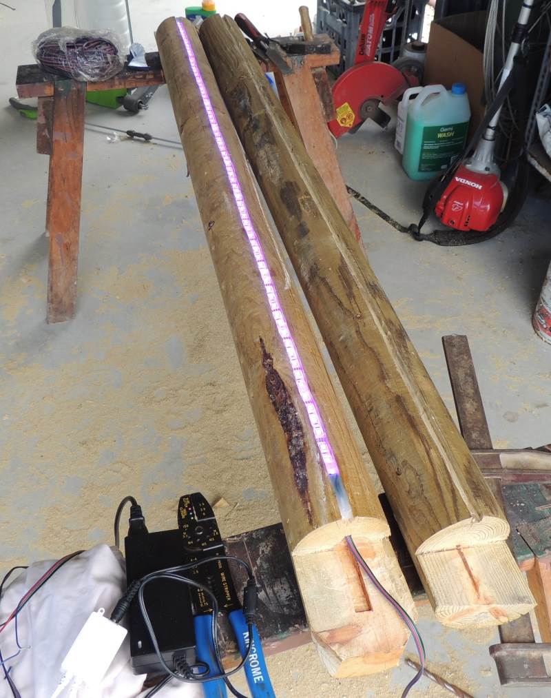
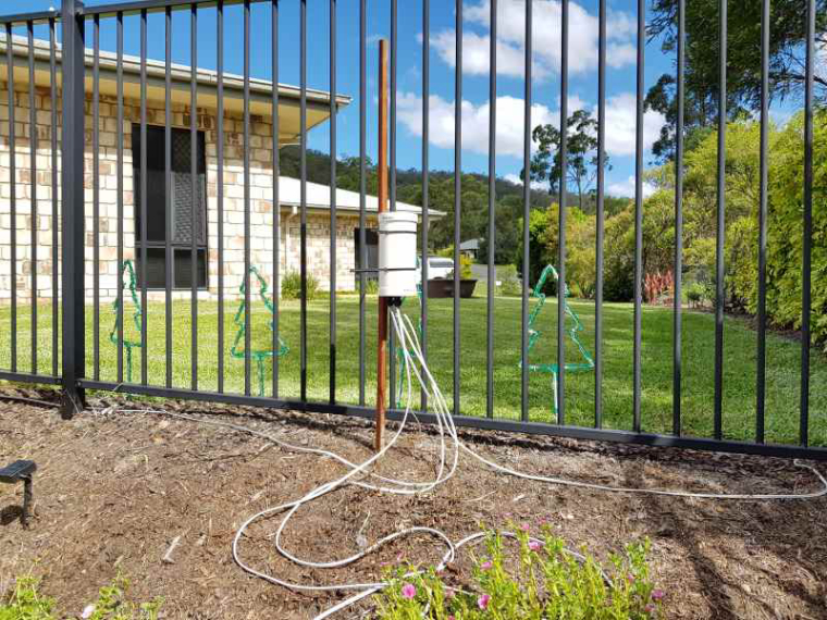
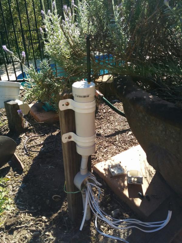
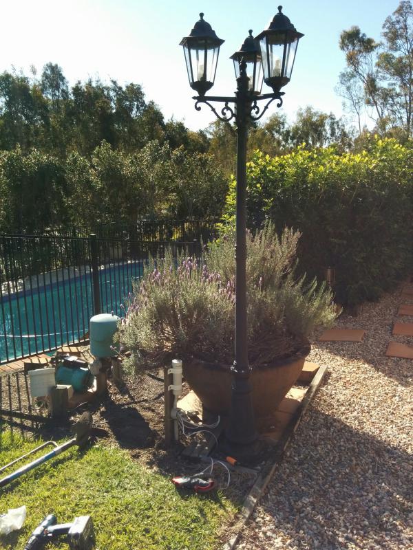
      I have installed a node to monitor our 12v auxiliary supply for our home. The power system consists of a 200w panel on the roof and a 105AH battery located in our server cabinet. When we built our home I ran a 12v Backbone as well so we can access the low voltage power all over . To date it has been used to run a system of night lights and reading lamps but now that I have found Mysensors I hope it will soon be powering a lot more 🙂 .

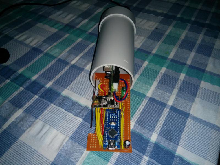
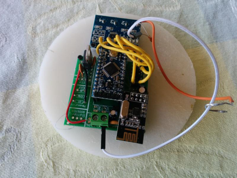
      Ok this node has been running for a few weeks now so thought i would share it with others. it monitors battery voltage, Charge current, Dis-charge current, Ambient temp and battery Temp. I have included the temperature monitors after a friend had his battery develop an internal short and melt in his caravan, not a pretty sight.

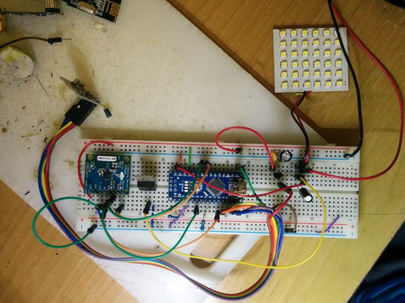
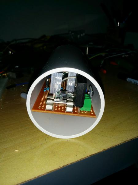
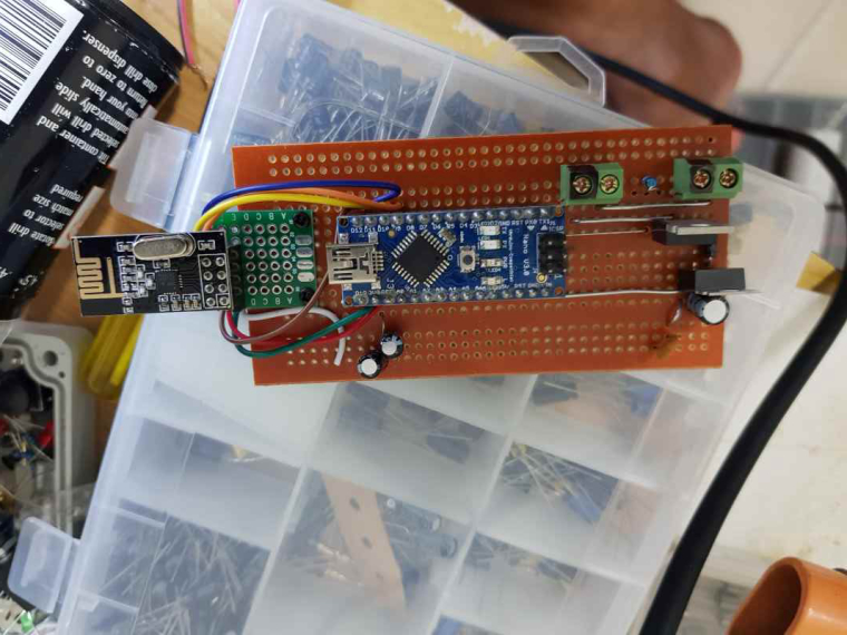
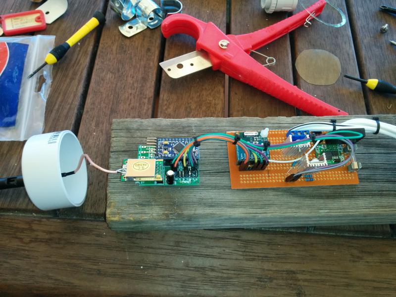
      My notes are based on my breadboard version which was built around an Arduino nano, In the final I used a Pro Mini.

      Parts List:

      1 x Arduino I have used a Nano but other types or OK too
      1 x ACS712 Current sensing Module. These are available in 5A, 20A and 30A. Choose whichever current fills your needs. Only one line of code needs to be modified to suit your selected device.
      2 x DS18b20 Temperature sensors
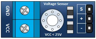
      1 x Voltage sensing module or 2 x resistors to be used as a voltage divider. I have used a module that has a maximum reading of 25v. That means when the module sees 25v on its input the output of the module will be 5v.
      1 x nRF24L01+ 2.4ghz Transceiver
      1 x LM2596 regulator module or some other regulator able to supply 5v
      1x 330 ohm resistor
      1x 4.7 k ohm resistor
      1x LED
      1x push button

      When using the analog inputs of the Arduino it is very important that you have a very stable 5v supply voltage. The 20A ACS712 shows a change of only 100mv for every 1A so you can see even small fluctuations can cause sizable errors in your readings. During construction I found powering the circuit from the usb port to give unreliable results and opted for a dedicated 5v supply instead.
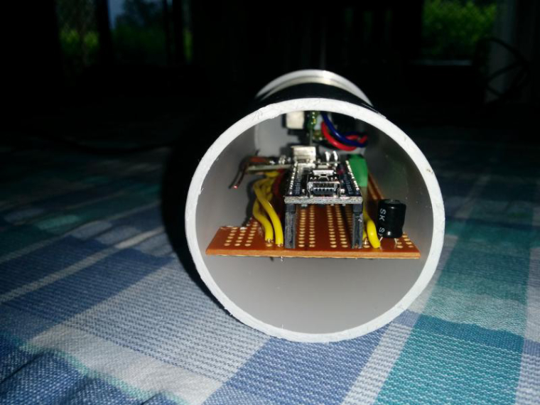
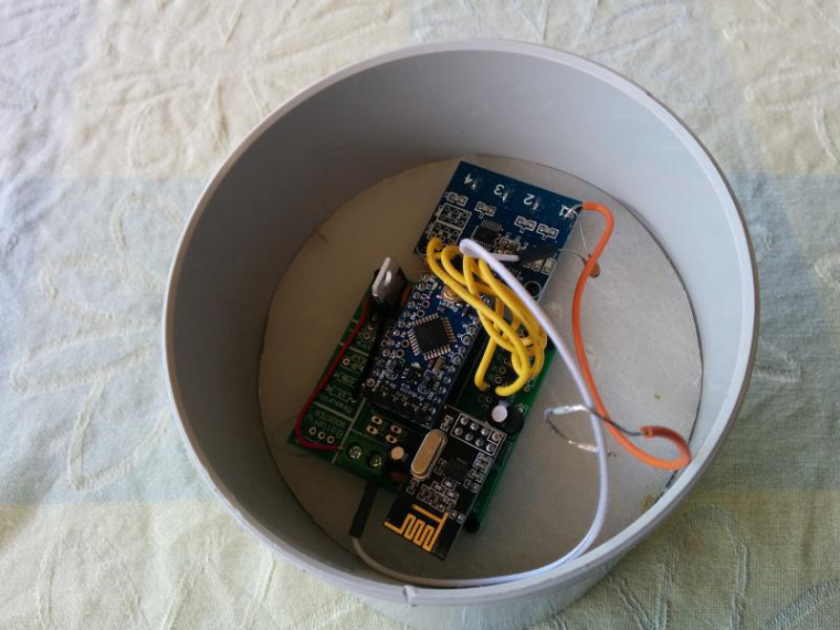
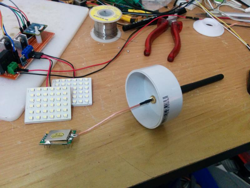
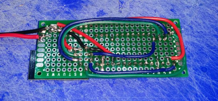
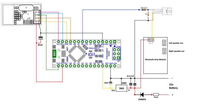
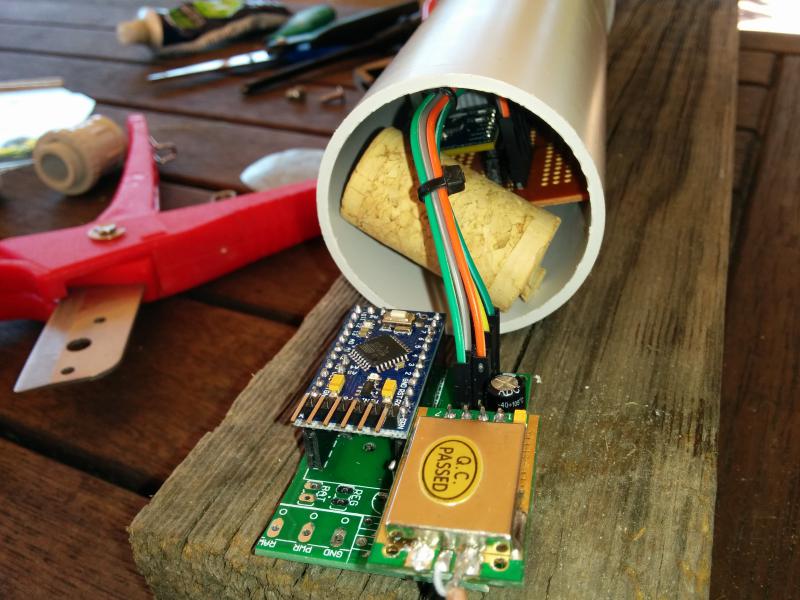
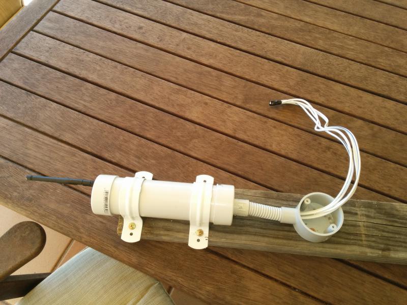
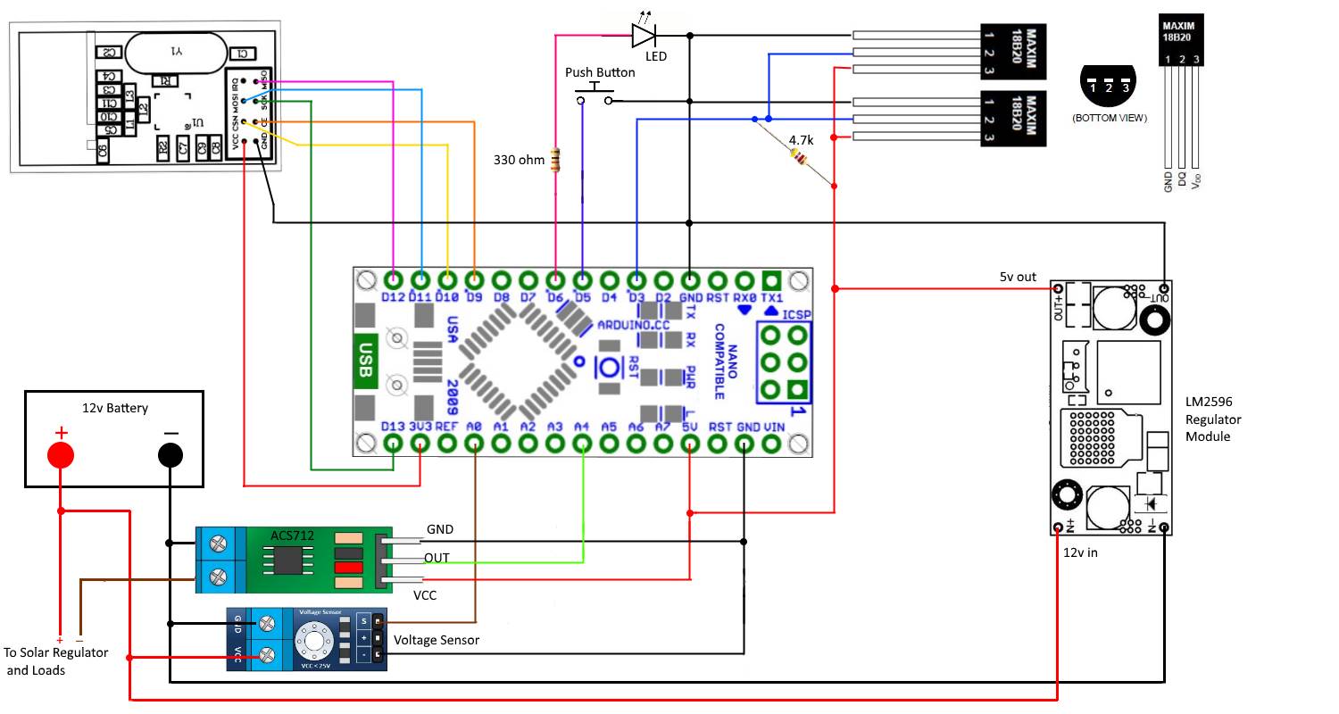
      Construction:
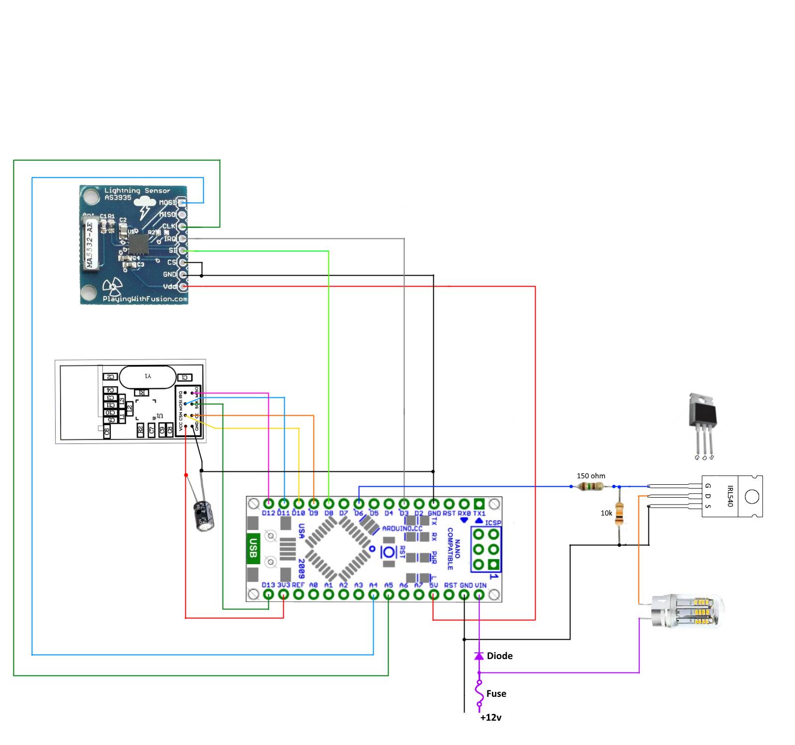
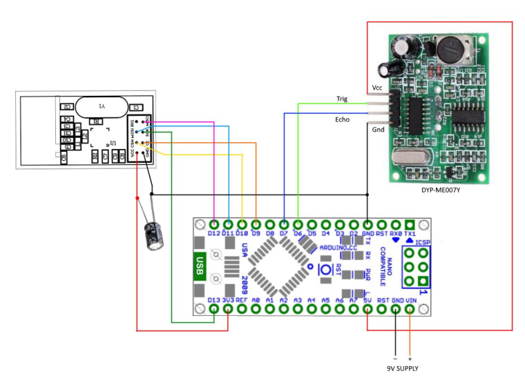
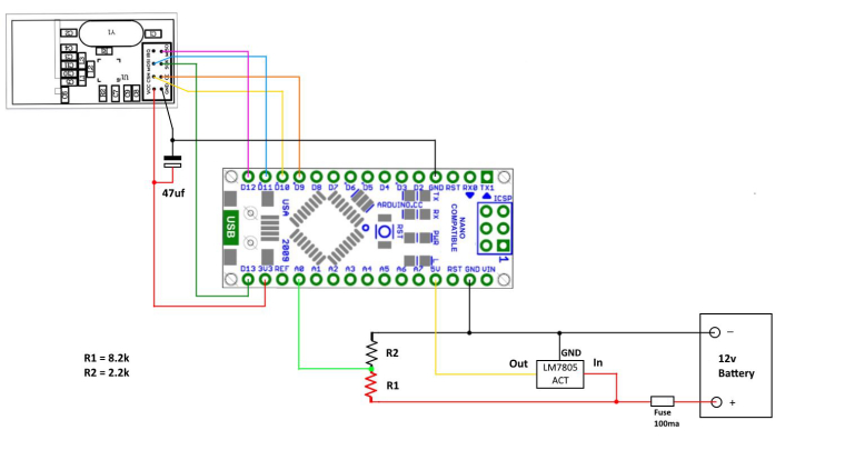
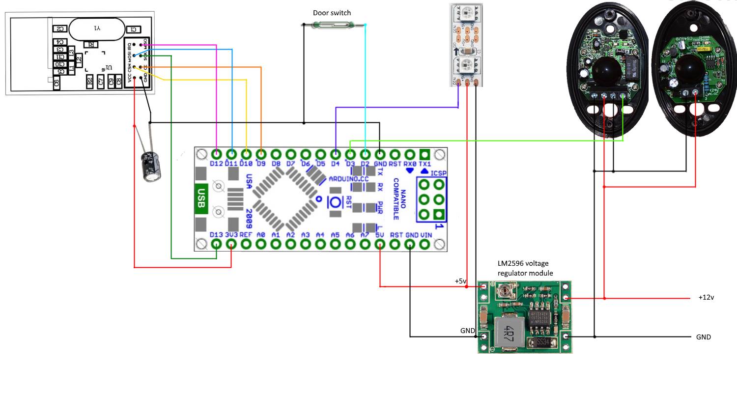
      Wire the devices as shown below.

      0_1462608111680_Batmon hookup.jpg

      The Sketch:

       /*Sketch for a MySensor node to monitor a 12v battery with a solar panel for charging
       * The node monitors battery voltage,current into and out of the battery, ambient temperature and battery temperature.
       * 2 x DS18b20 dallas temperature ic's their data pins connected to arduino digital pin 3
       * 1 x ACS712 current sensor module connected to  arduino analog pin A4
       * 1 x 25v voltage sensor module connected to arduino analog pin A0
       * 1 x nRF24L01+  2.4ghz tranceiver connected as per the MySensors web site.
       * 1 x LED connected via a 330 ohm resistor to pin 6
       * 1 x push button connected to pin 5
       */
       
      #include <MySensor.h>  
      #include <SPI.h>
      #include <OneWire.h>
      #include <DallasTemperature.h>
       
      
      #define ONE_WIRE_BUS 3                       // Ds18b20 data wire is connected to digital pin 3 on the Arduino
      #define ID_S_TEMPA 0                         // First temp device
      #define ID_S_TEMPB 1                         // second temp device
      #define ID_S_MULTIMETERV 3                   // Multimeter device for voltage measurement
      #define ID_S_MULTIMETERC 4                   // Multimeter device for positive current measurement 
      #define ID_S_MULTIMETERC1 5                  // Multimeter device for negative current measurement
      #define NUM_SAMPLES 10                       // number of analog voltage samples to take per reading
      
      
      int ledPin = 6;                               // the pin for the LED
      int buttonPin = 5;                            // the input pin for offset pushbutton
      int buttonState = 0;                          // variable for reading the pin status
      unsigned long SLEEP_TIME = 30000;            // Sleep time between reads (in milliseconds)
      int lastmilli = 25000;                       // set to an arbitary number outside of expected current sensor range to ensure a change when first run 
      float sensitivity = 100 ;                    //change this to 185 for ACS712-5 or to 100 for ACS712-20A or to 66 for ACS712-30A
      int VQ = 0;                                  //Placeholder for quiescent voltage calculations
      int ACSPin = A4;                             // Analog pin number the ACS712 data pin connects to
      float lastTemperature[2];                    //Array to hold the last temp readings sent to gateway, only send new data if different
      int sum = 0;                                 // sum of voltage samples taken
      unsigned char sample_count = 0;              // current sample number
      int lastVoltage = 30000;                     // set to an arbitary number outside of expected voltage sensor range to ensure a change when first run
      int voltagePin = A0;                         // analog pin voltage sensor or voltage divider is connected to
      int voltSenseMax = 25000;                    // set to the maximum input voltage in millivolts of your voltage divider input    
      OneWire oneWire(ONE_WIRE_BUS);               // Setup a oneWire instance to communicate with any OneWire devices (not just Maxim/Dallas temperature ICs)
      DallasTemperature sensors(&oneWire);         // Pass our oneWire reference to Dallas Temperature.
      
      MySensor gw;
      
      // ------ Initialize  messages -------
      MyMessage msg(0,V_TEMP);                     
      MyMessage msg_S_MULTIMETERv(ID_S_MULTIMETERV,V_VOLTAGE);
      MyMessage msg_S_MULTIMETERc(ID_S_MULTIMETERC,V_CURRENT);
      MyMessage msg_S_MULTIMETERc1(ID_S_MULTIMETERC1,V_CURRENT); 
      
      void setup()
      {
       
      sensors.begin();                                    // Start up the onewire library
      gw.begin();                                         // Startup and initialize MySensors library. Set callback for incoming messages. 
      gw.sendSketchInfo("Battery Status Sensor", "1");    // Send the sketch version information to the gateway and Controller
      
      // ------ Present all sensors to controller ------
      gw.present(ID_S_TEMPA, S_TEMP);
      gw.present(ID_S_TEMPB, S_TEMP);
      gw.present(ID_S_MULTIMETERV,V_VOLTAGE);
      gw.present(ID_S_MULTIMETERC,V_CURRENT);
      gw.present(ID_S_MULTIMETERC1,V_CURRENT);
      
      
      pinMode(buttonPin, INPUT_PULLUP);                     // Set buttonPin as input and turn on internal pull up resistor
      pinMode(ledPin, OUTPUT);                              // Set ledPin as output
      digitalWrite(ledPin, LOW);                            // Make sure ledPin is off
      
      // ------ load offset for current sensor
      int validCheck = gw.loadState(0);
      if (validCheck == 120){                          // check to see if valid data exists
        VQ = gw.loadState(1);                               // Load count offset into VQ
      //  Serial.print(" positive VQ offset loaded..."); Serial.println(VQ);
       }
       else if (validCheck == 125) {
        VQ = -abs(gw.loadState(1));
      //  Serial.print(" negative VQ offset loaded..."); Serial.println(VQ);
       }
      else {
      // Serial.println("VQ offset not set");
      }
      
      delay(500);  
      }
       
      void loop()
      {
      
      buttonState = digitalRead(buttonPin);
      //Serial.print("buttonstate..."); Serial.println(buttonState);
       if (buttonState == LOW) {
          VQ = determineVQ(ACSPin);                           //Returns the offset count needed to show zero with no load
      
          
        if (VQ >= 0 && VQ < 255) {                              //check for valid data. VQ is positive number
          gw.saveState(0, 120);                               // Store 120 value  in eeprom position 0. use this to check for valid data at boot
          gw.saveState(1, VQ);                                // Store offset count in eeprom. in case of re-boot  
        }
        else if (VQ < 0 && VQ > -255) {                              // VQ is a negative number. negatives cannot be stored in eeprom
          gw.saveState(0, 125);                               // Store 125 value  in eeprom position 0. use this to check for valid data at boot
          gw.saveState(1, abs(VQ));                                // convert VQ to positive and  Store offset count in eeprom. in case of re-boot   
        }
      
        }
      
      // ------------------ Start voltage readings --------------------
       
      
       sample_count = 0;
       sum = 0;
       while (sample_count < NUM_SAMPLES) {                                   // take a number of voltage samples  
        sum += analogRead(voltagePin);
        sample_count++;
        delay(10);
       }
      //Serial.print("sum count..."); Serial.println((sum / NUM_SAMPLES));      // print the count result. will be between 0 and 1023
      int voltageI = map(sum/NUM_SAMPLES,0,1023,0,voltSenseMax);              // map the reading and get our result in millivolts
      //Serial.print("mapped volts..."); Serial.println(voltageI / 1000.0, 1);  // convert millivolts back to volts and print. the 1 at the end determines how many decimal places to show
      
      
      if ( voltageI != lastVoltage) {                                         // check if we have a new value. only send data if it is different
       gw.send(msg_S_MULTIMETERv.set(voltageI / 1000.0, 1));                  // voltagel is in millivolts so we divide by 1000 to convert back to volts and
                                                                              // send voltage message to gateway with 1 decimal place
       lastVoltage = voltageI;                                                // copy the current voltage reading for testing on the next loop 
      }
      
      //--------------------Start Current readings---------------------------------
      
      int milli = readCurrent(ACSPin);                                       // take a reading from the ACS712 and send to the readcurrent function
      
      //Serial.print("Milliamps..."); Serial.println(milli);                   // print the value (in milliamps) returned
      
      if ( milli != lastmilli)                                               // check if value has changed
      {
       if ( milli > 0)                                                       // Battery is charging
       {
        gw.send(msg_S_MULTIMETERc.set(milli/1000.0, 1));                     // Send new data to charging amp device
        gw.send(msg_S_MULTIMETERc1.set(0));                                  // set the dis-charging amp device to zero
        lastmilli =  milli;
       }
       else if (milli < 0)                                                  // Battery is discharging
       {
        gw.send(msg_S_MULTIMETERc.set(0));                                  // set the charging amp device to zero
        gw.send(msg_S_MULTIMETERc1.set(abs(milli)/1000.0, 1));             //  use abs(milli) to Send a positive number  to dis-charging amp device
        lastmilli =  milli; 
       }
      else                                                                // No current flowing, set both to zero
      {
       gw.send(msg_S_MULTIMETERc.set(0));
       gw.send(msg_S_MULTIMETERc1.set(0));
       lastmilli =  milli;
      }
      }
       
      //----------------------Teperature readings start------------------------
        
        Serial.println(" Requesting temperatures...");
       
       // Fetch temperatures from Dallas sensors
        sensors.requestTemperatures();                  // call sensors.requestTemperatures() to issue a global temperature request to all devices on the bus
      
        // ------- query conversion time and sleep until conversion completed ------
        int16_t conversionTime = sensors.millisToWaitForConversion(sensors.getResolution());
        gw.sleep(conversionTime);
      
       for (int i=0; i<2; i++) {
      //  Serial.print("Temperature for Device: ");Serial.print(i);Serial.print(" is: ");
       // Serial.println(sensors.getTempCByIndex(i)); // Why "byIndex"? 
          // You can have more than one IC on the same bus. 
          // 0 refers to the first IC on the wire
      
       float temperature = static_cast<float>(static_cast<int>((sensors.getTempCByIndex(i)) * 10.)) / 10.;  // Fetch and round temperature to one decimal in celcius
      
      if (lastTemperature[i] != temperature)               // check for a changed temperature reading
        {
         gw.send(msg.setSensor(i).set(temperature,1));     // Send in the new temperature
         lastTemperature[i]=temperature;                   // Save new temperatures for next compare
        }     
      }
      gw.sleep(SLEEP_TIME);
      }


      /*-------------- Function to get the offset required for ACS712 to show zero with no current flowing -----------------*/
      int determineVQ(int PIN)                  
       {
        digitalWrite(ledPin, HIGH);                                      // Turn on LED to indicate offset being calculated
        delay(500);                                                      // Delay to hold LED on
        digitalWrite(ledPin, LOW);                                       // Turn off LED
        delay(150);                                                      // Delay to let readings stabilise
      //  Serial.print("estimating avg. quiscent voltage:");
        long acsCount = 0;
        for (int i=0; i<5000; i++)                                       //read 5000 samples to stabilise value
         {
          acsCount += analogRead(PIN);                                   // read the count value between 0 and 1023 and add it to acsCount
          delay(1);                                           
         }
        acsCount /= 5000;                                                      // acsCount now eaquals the average of the 5000 readings taken
      //  Serial.print(map(acsCount, 0, 1023, 0, 5000));Serial.println(" mV");   //Print the avg in millivolts
      //  Serial.print("acsCount:");Serial.println(acsCount);                               //Print the actual count value
        
        return int(acsCount - 512);                                            // return the count difference. 512 is the count for 2.5v which is what the reading should be with no current flow                           
        
      }
      
      
       /*--------------- Function to read current flowing ------------------*/
       
      int readCurrent(int PIN) 
      {
       int count = 0;
       for (int i=0; i<5; i++)                                        //read 5 analog count samples to stabilise value
        {
         count += analogRead(PIN) - VQ;                               //subtract the offset count VQ to improve accuracy
         delay(1);
       //  Serial.print("raw count..."); Serial.println(count);
        }
       /* Notes on the conversion below
        *  .00488 is the volt value per count of the arduino adc. The analog pin measures from 0 to 5 volt and then assigns the result to 
        *  a count from 0 to 1023, thats 1024 counts including zero. If we devide 5v by 1024 we get .oo488 volts for each count.  
        *  
        *  The (count/5) just gets us the average of our 5 count samples.
        *  
        *  So after the first part of the equation  (.00488 * (count/5) is complete we have converted our count reading into volts. 
        *  
        *  The ACS712 can measure current flow in both directions so it outputs a voltage of  2.5v as it's center point (when no current is flowing).
        *  To allow for this offset we must subtract the 2.5v to center our voltage reading.
        *  
        * Thats what the next part does (.00488 * (count/5)) - 2.5) After this is complete we are left with either a negative or  positive voltage
        * reading or a reading of zero for no current flow.
        * 
        * NOTE: While the ACS712 is a 5v device it does not use the full 0 to 5v for it's output. The datasheet shows the 20A version has a sensitivity of
        *  100mv per amp, so if we multiply 100mv by 20 we get 2v.  That means the 20A ACS712 has an output range from .5v to 4.5v.  
        * 
        * So to convert our reading in volts to a reading in amps we need to add the last part ((.00488 * (count/5)) - 2.5)/(sensitivity/1000).
        * The variable sensitivity is defined at the begining of the sketch and holds the ACS712 sensitvity amount, it is stored in millivolts. 
        * That is 66mv for the 30amp,  100mv for the 20amp and 185mv for the 5amp. As sensitivity is in millivolts we need to devide it by 1000 
        * to convert it back to volts so we can use it in the equation. 
        * 
        * Now we have our Amps value stored in the float amps. Integers are much easier to work with when checking for zero so we multiply by 1000 
        * to convert it to milliamps and return it as an integer.
      */
      
      //Serial.print("VQ = ..."); Serial.println(VQ);
      //Serial.print("current count..."); Serial.println(count/5);
      //Serial.print("map  milliamps..."); Serial.println(map((count/5), 102, 922, -20000, 20000));
       float amps = ((.00488 * (count/5)) - 2.5) / (sensitivity/1000);
      // Serial.print("float amps..."); Serial.println(amps, 1);
        return int (amps * 1000);                                         // convert to milliamps and return as an integer
      
      }
      

      Voltage Sensor:
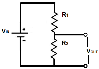
      If you are not using a voltage sensor module you will need to construct a voltage divider circuit to measure the battery voltage. The reason for this is the Arduino Nano can only tolerate a maximum of 5v on its analog inputs so if we were to connect the 12v battery directly to the input we would most likely destroy the Arduino. A google search will turn up plenty of online voltage divider calculators to help you decide on the correct resistor values.
      Make sure you choose an input voltage level for your divider that is well over the maximum of the voltage you intend to measure.
      Our 12v system is likely to see voltages as high as 14.5v to 15v when charging and perhaps even higher if something has gone wrong so a divider with an input voltage of 25 to 30 volts would be a good choice. So for example if we were to use a combination of a 30k for R1 and 7.5k for R2 an input of 25v would result in an output of 5v.
      You will need to change the value in the sketch code int voltSenseMax = 25000; to represent the input voltage in millivolts of your divider
      I am using millivolts as I use the map function for the conversion later in the sketch, so integers are required. A typical voltage divider circuit is shown below.

      0_1462662603329_Voltage-divider-circuit.png

      If you are using the voltage sensor module that I have used you will notice it has three terminals on the output side, the one marked with a + symbol is not used, I am not sure why it is even there.

      0_1462662681538_25v module.png

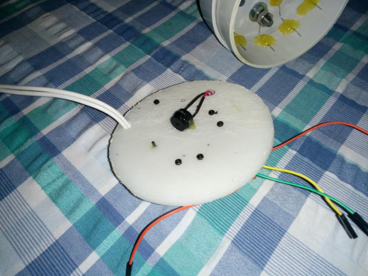
      DS18b20 Temperature Sensors:
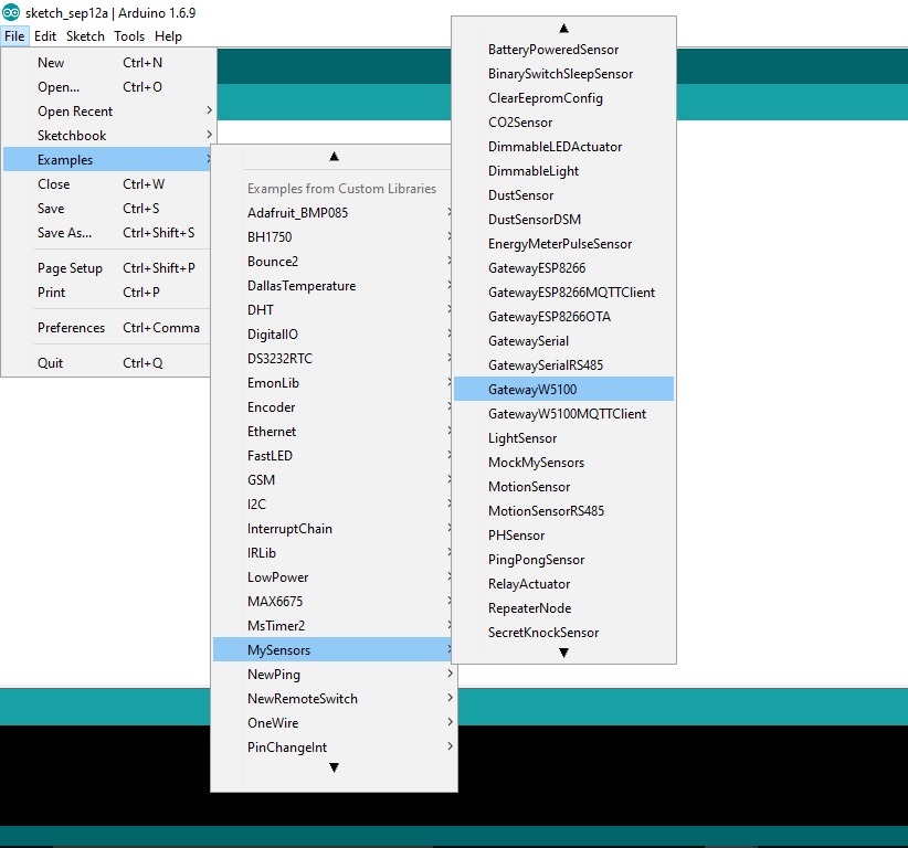
      These devices can be used with just two wires but I have used three as it seems this works best in noisy environments. The big advantage of these “one wire” devices is you can have more than one connected to the same input pin on the Arduino. The only requirement is one 4.7k pull-up resistor connected between VDD and DQ. The code I have used is based on the MySensors Dallas Temperature example.

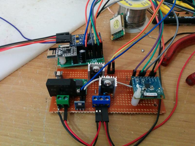
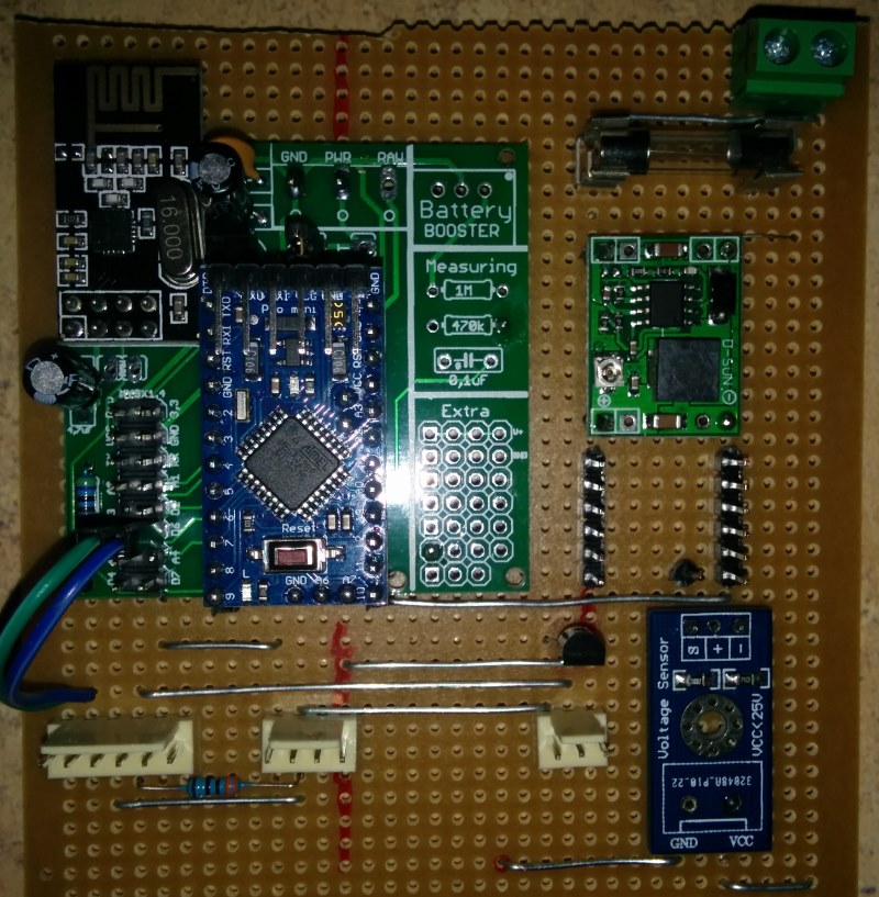
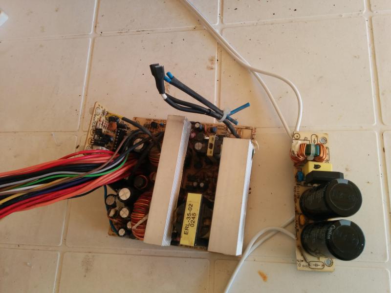
      ACS712 Current Sensing Module:

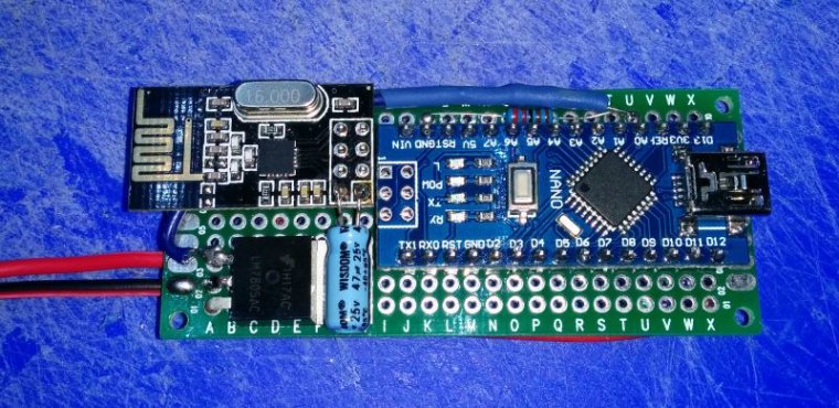
      First be aware that the pin out can vary on these modules so check before you connect up. You can see in the picture below that the VCC and GND pins are reversed on these two.

      0_1462662998444_acs.jpg

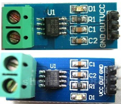
      The ACS712 current sensing module is a 5v device that measures current flow and returns a voltage that can be used to determine the amount of current flowing. It is available in three versions 5A, 20A and 30A .
      Importantly for this application they read current flow in both directions. To do this they output 2.5v when no current is flowing and increase or decrease the voltage depending on which direction the current is flowing.
      None of them use the full 0 to 5v range for their output, the 20A version I have used has a sensitivity value of 100mv per 1A of current flow. As this is a 20A device we can multiply the 100mv by 20 and we get 2000mv or a 2v change for 20amps. We know the ACS712 shows an output of 2.5v when no current is flowing so using the 2v we now have the output range from .5v to 4.5v.
      To use this device then we need a way to convert its voltage output to a measurement in amps.

      Here is the basic equation needed

      amps = ((voltsPerCount * count) – offsetVolts) / sensitivityVolts

      Where

      VoltsPerCount is the volt value per count of the Arduino ADC. The ADC measures the voltage present at the analog pin (0 to 5 volt) and then assigns the result as a count from 0 to 1023, that's 1024 counts including zero. If we divide 5v by 1024 we get .00488 volts for each count. So VoltsPerCount = .00488 Volts

      count is the value our Arduino ADC returns after processing the output from the ACS712.

      So after the first part of the equation (.00488 * (count) is complete we have converted our count reading from the arduino into volts.

      The ACS712 can measure current flow in both directions so it outputs a voltage of 2.5v as it's center point (when no current is flowing). To allow for this offset we must subtract the 2.5v to center a 2.5 voltage reading at zero. So offsetVolts = 2.5 Volts

      That's what the next part does ((.00488 * (count)) - 2.5) After this is complete we are left with a negative or positive voltage for current flowing in either direction or a value of zero for no current flow.

      The sensitivity values for the ACS712 are shown on the datasheet as

      185mv per Amp for the 5A
      100mv per Amp for the 20A
      66mv per Amp for the 30A

      So to convert our value in volts to a value in amps we need to add the last part
      ((.00488 * (count)) – 2.5)/sensitivityVolts

      Where sensitivityVolts equals the sensitivity value in volts for the device you are using. In my case the 20A version 100mv = .1 volts

        amps = ((.00488 * (count)) – 2.5) / .1
      

      Another way to do this would be to use the Arduino map function
      we worked out earlier that the 20A version would output in the range from .5 to 4.5 volts, to convert that to count values we need to divide by .00488 .
      Which gives us .5 / .00488 = 102 and 4.5 / .00488 = 922. map can only work with integers so it is best to use milliamps instead of amps for the output result.

      The Arduino code for the 20A ACS712 would be:

           milliamps =  map(count, 102, 922, -20000, 20000);
      

      Both of the above methods give very close results so you could use either. I have used the first method as it is easier to select the version of ACS712 you are using by changing the sensitivity.

      The ACS712 is a hall effect device so it can be affected by stray magnetic fields that are nearby. It is best to locate it as far away as possible from any magnetic source to ensure you are getting a true reading. In use I found this was sometimes hard to achieve so I have added code to zero the reading if required. To do this I have used a push button and LED. If you are getting a constant current reading when no current is flowing simply push and hold the button until the led flashes. The sketch will then work out the offset required and apply that to zero the reading. This offset amount will then be saved to the Arduino EEPROM and will be reloaded and used even if the arduino is reset.

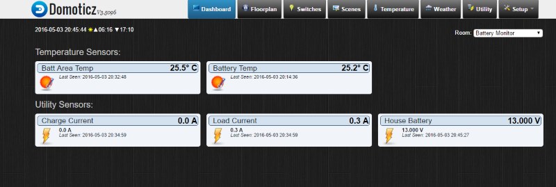
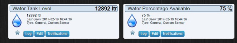
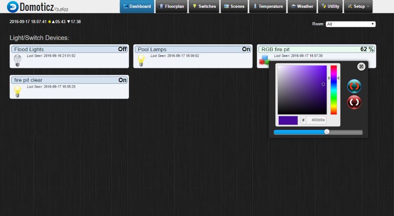
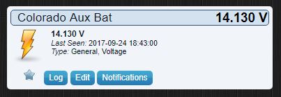
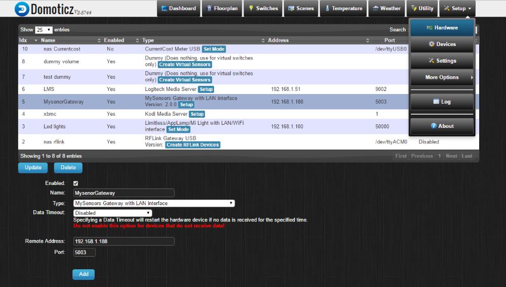
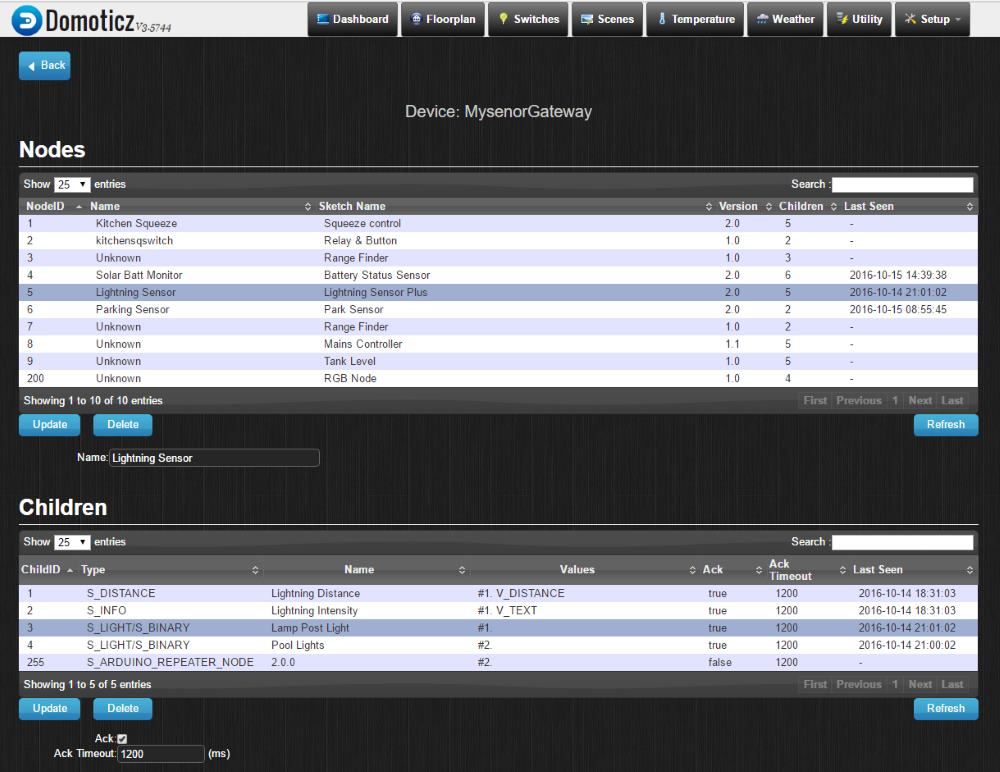
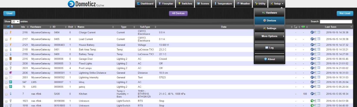
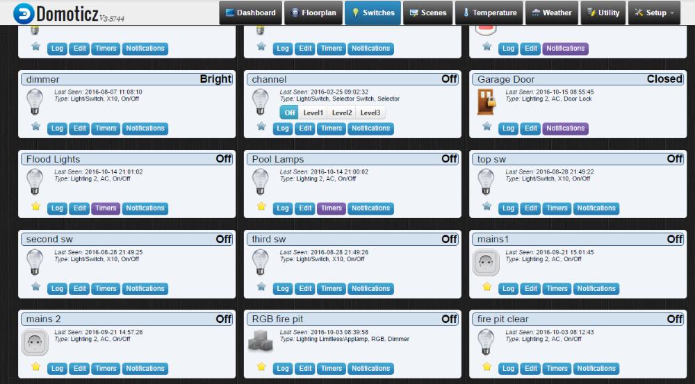
      I am using Domoticz as my controller, here is what the end result looks like.

      0_1462664203469_dom.jpg

      posted in My Project
      Boots33
      Boots33
    • RE: MY_TRANSPORT_DONT_CARE_MODE

      @okos said:

      I would like to ask whether it is normal that the switch does not work if the server domoticz off? I want to use the switch only crash server 😳 now i cant"

      Yes that is correct. The "relay with button actuator" sketch relies on an ack back from the controller to do the actual switching. so if the Gateway or Controller go down the local switch will also no longer work

      And i got a reply from @hek it will be in the new library.(post 90)
      Now i see 2.1.0 , and i have question now it is work?

      MY_TRANSPORT_DONT_CARE_MODE has been deprecated and did not make it into MySensors 2.1. As @Fabien has said you now need to use MY_TRANSPORT_WAIT_READY_MS instead.

      What I need to change in the code or configurations (MyConfig.h) to work the physical switch when the failure of the gateway.

      You have two choices, you can modify your MyConfig.h file or Define the change at the top of your sketch.
      If You have a look at the MyConfig.h file you will see that at around line 179 is the area you need to be looking at. The default value is 0 which means no timeout so the sketch will not proceed to the loop part if a connection is not established.
      However I think the best solution will be to Define the change in your sketch rather than change your config file.

      I have not used MY_TRANSPORT_WAIT_READY_MS before but it most likely will need to be added to the top of your sketch before the #include <MySensors.h> line.

      Like this

      // Enable debug prints to serial monitor
      #define MY_DEBUG
      
      // Enable and select radio type attached
      #define MY_RADIO_NRF24
      
      // Enabled repeater feature for this node
      #define MY_REPEATER_FEATURE
      
      //set how long to wait for transport ready. in milliseconds
      #define MY_TRANSPORT_WAIT_READY_MS 3000
      
      #include <SPI.h>
      #include <MySensors.h>
      #include <Bounce2.h>
      

      As this is only run once when the node first boots up you should allow plenty of time to start up normally if a connection is available. In the example above I have used 3 seconds but you may need to play with that to give your sketch the best chance of getting a connection without waiting too long.

      As noted earlier in my post even once you get your sketch to run the loop the switch still will not work without a connection to the controller. So you will need to make some other changes to the sketch as well.

      @hek Has given you a good start with the code modifications needed with the post above. There will be other issues to consider such as keeping the controller in sync with the node but best to get the basics right first then add the extras later.

      posted in Troubleshooting
      Boots33
      Boots33
    • Round water tank level sensor

      This describes a water tank level sensor for use in a MySensors network. It uses a DYP-ME007Y waterproof ultrasonic sensor to determine the height of water in a round tank. Based on the water height it then works out the amount of water available in litres and also the percentage of water available. Then the results are transmitted via the MySensors network back to the controller.

      At this time I have not permanently mounted this node to the tank but in testing it does seem to work ok. I will post back when the whole thing is finished but wanted to share the project so far.

      The DYP-ME007Y is a bit fussy about the correct voltage. It needs a good solid 5v supply if you want to get a stable reading. It has a stated range from 30cm to 350cm.
      The 30cm minimum may prove a problem in some tanks if you do not have the space above the full water line but it worked out ok for my situation. In testing I could get stable readings down to 25cm but under that it became unreliable.

      Initially I also had problems with unstable readings once I got over 120cm but this turned out to be caused by a a lack of power while using the USB connection. Once the unit was powered from an external source delivering a good 5v supply the DYP-ME007Y performed within spec.
      This is a repeater node so I am using a Di-pole antenna on the nrf to increase range. I have found this mod to give good results so is worth the effort if you have room for the leads.

      The node will be mounted in a round 50mm pvc case. I have several outside nodes using these now, they are very easy to construct, totally rain proof and allow easy access to the arduino for updates etc.

      The sketch is running on MySensors V2.1.1
      I am using the NewPing library to interact with the DYP-ME007Y
      I use sonar.ping_median(5) to take 5 readings and return the median of the results. This will hopefully reduce the amount of incorrect readings.
      I also constrain the return from the DYP-ME007Y so the readings stay within the known limits of the tank.
      I am using the map function to work out the percentage of water available

      There are a few variables you will need to change to suit your particular tank. Refer to the picture below. All measurements are in cm.

      sensHeight: is the distance from the transducer to the height of the water when the tank is full. The full level will usually be the bottom edge of your overflow outlet. Remember with the DYP-ME007Y this has to be at least 25cm.

      fullHeight: Is the distance from the bottom of the tank to the level of water when the tank is full.

      outletHeight: is the distance from the bottom of the tank to the level you want to be shown as empty. As it is not good for a pump to suck air you would usually make this a comfortable distance above the water outlet.

      tankRad: Radius of tank

      0_1487490226951_TankNoReserve.jpg

      Sketch:

      /* 
      Sketch to read level of water in a round tank and  then send data back to controller
      uses MySensors V2 .
      
      Libraries used
      MySensors          https://www.mysensors.org/
      NewPing            https://bitbucket.org/teckel12/arduino-new-ping/wiki/Home
      SPI                 installed with arduino IDE
      
      */
      
      // Enable debug prints to serial monitor
      #define MY_DEBUG 
      
      // Enable and select radio type attached
      #define MY_RADIO_NRF24
      // Enabled repeater feature for this node
      #define MY_REPEATER_FEATURE
      // #define MY_NODE_ID 9    // comment out this line if you use dynamic id's
      // #define MY_RF24_CHANNEL 84    // channel of nrf network
      
      #include <MySensors.h>
      #include <SPI.h>
      #include <NewPing.h>
      
      
      #define CHILD_ID_WATER 1
      #define CHILD_ID_PERCENT 2
      
      
      // newping settings
      #define TRIGGER_PIN  6                  // Arduino pin 6 connected to trigger pin on the ultrasonic sensor.
      #define ECHO_PIN     7                  // Arduino pin 7 connected to echo pin on the ultrasonic sensor.
      #define MAX_DISTANCE 240                // Maximum distance we want to ping for (in centimeters). you should set this to be 
                                              // a bit more than fullHeight + sensHeight.
      
      /*------change these to suit your tank setup-----*/
      const int tankRad = 170;                // Radius of tank in cm
      const int fullHeight = 198;             // Height of water when tank full in cm
      const int sensHeight = 30;              // height of sensor above full water mark in cm
      const int outletHeight = 7;             // height of water when tank reading will show empty in cm
      /*----------------------------------------------*/
      unsigned long heartbeatDelay = 120;     // how often the heartbeat will be sent, in minutes
      unsigned long lastHeartbeat = millis(); // holder for last time heartbeat was sent
      unsigned long waitTime = 6000;          // delay in milliseconds to set time between data readings 
      unsigned long pingHeight;               // holds total height from ultrasonic sender to current water height
      unsigned int waterAvail;                // holds current water available in litres
      byte oldWaterPercent; 
      byte waterPercent = 0 ;                 // used to hold the tank water level percentage
      
      // NewPing setup of pins and maximum distance.
      NewPing sonar(TRIGGER_PIN, ECHO_PIN, MAX_DISTANCE); 
      
      MyMessage msgVolume(CHILD_ID_WATER, V_LEVEL);              //water availble in liters
      MyMessage msgPercent(CHILD_ID_PERCENT, V_LEVEL);           // water percentsge available
      
      void setup() {
      
      }
      
      
      void presentation()  {
        // Send the sketch version information to the gateway and Controller
        sendSketchInfo("Tank Level", "1.0");
      
        // Register all sensors to gateway (they will be created as child devices)
        present(CHILD_ID_WATER, S_DUST,"Water Available");
        present(CHILD_ID_PERCENT, S_DUST,"Water Percentage Available");
      }
       
      
       void loop()
       { 
       
       
         data_calc();      // perform calculations to get water remaining etc.
       
       
        if(oldWaterPercent != waterPercent) {         //check to see if new water data is available  
        send(msgVolume.set(waterAvail));
        send(msgPercent.set(waterPercent));
        oldWaterPercent = waterPercent;
        }   
       
        heartbeatCheck();                                    // call heartbeat function
       
        wait(waitTime);  //Wait then back to loop
        
      }
      
      /*-------------------------start of functions-------------------*/
      
      void heartbeatCheck(){
      unsigned long millisNow = millis();           // get the current time
      if ((millisNow - lastHeartbeat) > (heartbeatDelay*60000)) {  
        sendHeartbeat();
        wait(5);
       // sendBatteryLevel(100);
        lastHeartbeat = millis();
        #ifdef MY_DEBUG
          Serial.println("Heartbeat Sent" );
        #endif
      }
      }
      
       void data_calc() {
       pingHeight = sonar.ping_median(5);             //- Do multiple (5) pings and return median
       pingHeight = sonar.convert_cm(pingHeight);     // then convert to cm
       #ifdef MY_DEBUG
        Serial.print("Ping Height raw in cm: ");
        Serial.println(pingHeight);
       #endif
       pingHeight  = constrain(pingHeight, sensHeight, (fullHeight-outletHeight)+sensHeight);     // keep pingHeight within the expected values
       waterPercent = map(pingHeight,sensHeight,(fullHeight-outletHeight)+sensHeight,100,0);           // calculate the percentage of water available
       waterAvail = PI* pow(tankRad,2)*(((fullHeight-outletHeight)+sensHeight)-pingHeight)/1000;    // calculate water available in litres
      
      // Write some debug info
        #ifdef MY_DEBUG
          Serial.print("Ping Height constrained in cm: ");
          Serial.println(pingHeight);
          Serial.print("Percentage Available: ");
          Serial.println(waterPercent);
          Serial.print("Litres Available: ");
          Serial.println(waterAvail);
        #endif
       }


      It might look a bit strange that i have used the dust sensor for the MySensors data but (in Domoticz at least) they allow for the best visualisation I think.

      0_1487490552307_Screenshot (46).jpg

      Wiring:

      0_1487490843740_wiring.jpg

      All the parts are mounted on a small prototype board. I cut away the board behind the antenna to allow for better reception. I also had to re-position the socket for the transducer to allow it all to fit in the tube.

      0_1487490750824_IMG_20170219_112051.jpg

      The board is then slid inside the tube

      0_1487490929849_IMG_20170219_164616.jpg

      0_1487490946006_IMG_20170219_164539.jpg

      The bottom cap is glued on to prevent moisture from entering but the top is just pressed on to allow easy access when needed. The arduino is positioned at the top so I can quickly connect a serial lead with the cap off. A water proof gland is used at the bottom for the power and transducer cables.

      0_1487491162803_IMG_20170219_164653.jpg

      posted in My Project
      Boots33
      Boots33
    • Outdoors Touch Switch light controller

      I have a few lights around the yard under MySensors control now so I am building a touch controller to turn them on and off. This will be located at the beginning of the main path that leads to our garden areas.

      The unit will be constructed using 100mm pvc pipe and connectors. There will be 4 touch studs, these will be stainless M8 cup head bolts.

      Here are the main parts to the housing. The end cap will be glued on the pipe and then partly buried. Once in the ground i will fill it with 20mm gravel to keep it stable. The touch studs and node electronics will all be located in the top joiner and cap.

      0_1490444849562_parts.jpg

      The joiner has a lip around the inside, i have used that to hold the arduino etc.

      0_1490445210961_joiner.jpg

      The mounting plate is made from an old plastic cutting board

      0_1490445345413_mounting plate.jpg

      It just slips into place and uses gravity to hold it there.

      0_1490445411976_in joiner.jpg

      The cap with the studs uses solid wire held in place with hot glue to run out to the touch switch wires . Single dupont connectors push directly on to these. It is important to keep the wires separate from each other to reduce the chance of cross triggering.

      0_1490445682964_cap wire.jpg

      I have also added a small piezo buzzer to give an audible beep when a stud is touched.

      0_1490445947355_buzzer.jpg

      The circuit diagram. This shows it with a nano but I have used a pro mini in the actual unit.

      0_1490446124503_touchPiezo.jpg

      The Sketch for the touch controller is below. It is working ok on the bench. As you can see three of the the buttons all switch the same node at the moment. I will change these to the correct id's once it is installed outside.

      /*  
       * This is a  MySensors node used to control
       * other Binary Switch nodes on the network.
       * It uses node to node messaging to control three nodes directly and a
       * binary switch sensor to be used as a group control in Domoticz
       * 4 way touch switch module for input.
      */
      
      // Enable debug prints to serial monitor
      #define MY_DEBUG
      //#define MY_PARENT_NODE_ID 1
      //#define MY_PARENT_NODE_IS_STATIC
      #define MY_NODE_ID 100
      #define GROUP_SW_ID 4
      
      // Enable and select radio type attached
      #define MY_RADIO_NRF24
      #define MY_RF24_CHANNEL 84
      #define MY_TRANSPORT_WAIT_READY_MS 3000
      //#include <SPI.h>
      #include <MySensors.h>
      
      uint8_t sensorId = 3;               // Id number of the sensor to send to
      uint8_t nodeId = 201;                 //Id number of the node to send to
      uint8_t sendingSensorId = 1;        // Id number of the sensor sending the message
      
      int buzzerPin = 7;          // arduino pin buzzer is connected to 
      int touchState[5] ;
      int oldTouchState[5] ;
      bool groupState = false;
      
      MyMessage msg(GROUP_SW_ID, V_STATUS);
      
      void setup()
      { 
       for(int i = 3; i < 7; i++){    //set Arduino digital pins 3 to 6 as inputs
         pinMode(i, INPUT);
       }
      }
      
      void presentation()  {
        // Send the sketch version information to the gateway and Controller
        sendSketchInfo("Touch controller", "1.0");
        // Register all sensors to gateway (they will be created as child devices)
        present(GROUP_SW_ID, S_BINARY, "Group controller switch");
        
      }
      
      void loop()
      {
      for ( int pinNo = 3, touchNo = 1; pinNo < 7; pinNo++, touchNo++){
          touchState[touchNo] = digitalRead(pinNo);                                                             // Get the current touch switch state
          if (touchState[touchNo] != oldTouchState[touchNo] && touchState[touchNo] == 1) {                      // check for new touch button push
            switch(touchNo){
             case 1:
               /*   Node to Node message format. Note: message is still routed through the gateway or repeater node,         *
                *                                      not diectly to destination Node.                                      *
                *                                                                                                            *
                *            : Id of sending  : message  :   Destination     :     Destination      : Payload                *
                *            :    sensor      :  Type    :    sensor Id      :       Node Id        :                        */ 
               send(MyMessage(sendingSensorId, V_STATUS).setSensor(sensorId).setDestination(nodeId).set(true));  //send message to desitination node from touch 1
               wait(5);
               tone(buzzerPin, 1200, 60);                                                                        //Play short beep to acknowledge touch.  PIN, TONE FREQUENCY, DURATION  
               break;
             case 2:
               send(MyMessage(sendingSensorId, V_STATUS).setSensor(sensorId).setDestination(nodeId).set(true));  //send message to desitination node from touch 2
               tone(buzzerPin, 1200, 60);                                                                        //Play short beep to acknowledge touch
               break;
               case 3:
               send(MyMessage(sendingSensorId, V_STATUS).setSensor(sensorId).setDestination(nodeId).set(true));  //send message to desitination node from touch 3
               tone(buzzerPin, 1200, 60);                                                                        //Play short beep to acknowledge touch
               break;
             case 4:
               groupState = !groupState ;                                                                          //Toggle the state
               send(msg.set(groupState), false);                                                                   // send new state to controller, no ack requested
               tone(buzzerPin, 1200, 60);                                                                          //Play short beep to acknowledge touch
               break;    
          }  
        }    
       }
       
       for (int i = 1; i < 5; i++){
        oldTouchState[i] = touchState[i];
       } 
      }
      
      void receive(const MyMessage &message) {
        if (message.type == V_STATUS && message.sensor == GROUP_SW_ID) {
          groupState = message.getBool();
        }
      }
      

      Here is the double binary switch node sketch I have been using as the test receiver.

      /* This sketch is to control two outdoor lights and also
       *  allow control from a remote switch 
      */
      
      // Enable debug prints to serial monitor
      #define MY_DEBUG
      
      // Enable and select radio type attached
      #define MY_RADIO_NRF24
      #define MY_RF24_CHANNEL 84
      //#define MY_PARENT_NODE_ID 1
      //#define MY_PARENT_NODE_IS_STATIC
      #define MY_NODE_ID 201
      
      
      //#include "SPI.h"
      #include <MySensors.h>
      
      #define LIGHT_PIN_A  6             // Arduino Digital I/O pin connected to mosfet 1
      #define LIGHT_PIN_B  7             // Arduino Digital I/O pin connected to mosfet 2
      #define LIGHT_ON 1                 // Output value to write to turn on attached mosfet
      #define LIGHT_OFF 0                // Output value to write to turn off attached mosfet
      #define CHILD_ID_LIGHT_A 3
      #define CHILD_ID_LIGHT_B 4
      
      unsigned long heartbeatDelay = 120;     // how often the heartbeat will be sent, in minutes
      unsigned long lastHeartbeat = millis(); // holder for last time heartbeat was sent
      bool stateA = 0;                        // State holder for light A
      bool stateB = 0;                        // State holder for light B
      
      MyMessage msgA(CHILD_ID_LIGHT_A, V_STATUS);
      MyMessage msgB(CHILD_ID_LIGHT_B, V_STATUS);
      
      void setup() {
        pinMode(LIGHT_PIN_A, OUTPUT);            //set light pin as output
        pinMode(LIGHT_PIN_B, OUTPUT);            //set light pin as output
        digitalWrite(LIGHT_PIN_A, LIGHT_OFF);    //   make sure light is off at startup
        digitalWrite(LIGHT_PIN_B, LIGHT_OFF);    //   make sure light is off at startup  
      }
      
      void presentation()  {
        // Send the sketch version information to the gateway and Controller
        sendSketchInfo("Light controller", "1.0");
        // Register all sensors to gateway (they will be created as child devices)
        present(CHILD_ID_LIGHT_A, S_BINARY, "Lamp Post Light");
        present(CHILD_ID_LIGHT_B, S_BINARY, "Garden Lights");
      }
      
      void loop()
      { 
       heartbeatCheck();                  // call heartbeat function
      }
      
      
      /*-------------------------start of functions-------------------*/
      
      void heartbeatCheck(){ 
       if ((millis() - lastHeartbeat) > (heartbeatDelay*60000)) {  
        sendHeartbeat();
        lastHeartbeat = millis();
        #ifdef MY_DEBUG
          Serial.println("Heartbeat Sent" );
        #endif
       }
      }
      
      void receive(const MyMessage &message) {
      
      if (message.type == V_STATUS) {                                  // check that message is for binary switch
        if (message.sender == 0) {                                     // check if message is from gateway (node 0)   
          switch (message.sensor) {
           case 3:                                                     //incoming message is for light A  (sensor 3)
             stateA = message.getBool();
             digitalWrite(LIGHT_PIN_A, stateA ? LIGHT_ON : LIGHT_OFF); // Set Light A to the new state
             break;
           case 4:                                                     //incoming message is for light B  (sensor 4)
             stateB = message.getBool();
             digitalWrite(LIGHT_PIN_B, stateB ? LIGHT_ON : LIGHT_OFF); // Set Light B to the new state
             break;       
         }   
        } 
        else  {                                                         // message is not from gateway so must be from a remote
          switch (message.sensor) {
            case 3:                                                     //incoming message is for light A (sensor 3) 
              stateA = !stateA;                                         // toggle light state
              digitalWrite(LIGHT_PIN_A, stateA ? LIGHT_ON : LIGHT_OFF); // Set Light A to the new state
              send(msgA.set(stateA), false);                            //Message the gateway so controller will be aware of the change. No ack
              break;
            case 4:                                                     //incoming message is for light B  (sensor 4)
              stateB = !stateB;                                         // toggle light state 
              digitalWrite(LIGHT_PIN_B, stateB ? LIGHT_ON : LIGHT_OFF); // Set Light B to the new state
              send(msgB.set(stateB ? true : false));                    //Message the gateway so controller will be aware of the change. No ack
              break;     
          }
         }
        } 
          /*-------Write some debug info-----*/
      #ifdef MY_DEBUG
          Serial.print("Incoming change for sensor:");
          Serial.print(message.sensor);
          Serial.print(" from node: ");
          Serial.println(message.sender);
      #endif  
      }


      posted in My Project
      Boots33
      Boots33
    • Fire pit RGB striplight controller

      I built a fire pit in our back yard using an old crusher mantle.

      0_1474105410511_pit2.jpg

      I wanted the area to look nice so added some led strip lighting to the underside of the railings

      0_1474105518826_DSCN0590.jpg

      There are some clear led garden lights as well. Together the make a very inviting place to entertain friends.

      0_1474105718510_combo.jpg

      and a very comfy place to relax on the cooler nights

      0_1474105787319_pit.jpg

      So now it is time to bring the lighting under Mysensors control. This is a work in progress and I will post wiring etc as I go but thought i would throw the sketch up for a start.

      This node will control the RGB strip as well as separate switch for the white garden lights. In Domoticz the RGB controller looks like this. It can be used to set the brightness and colour of the strip. I will be using mosfet's to control all of the lights.

      0_1474106133732_Screenshot (140).jpg

      The current sketch is working well on a breadboard prototype using a single RGB led . I will probably add some form of colour cycling as well as I progress.

      /*
      RGB LED Node for 12v common anode rgb strip,
      Also has a standard on/off switch to control an extra set of garden lights 
      PWM pins (3, 5, 6, 9, 10, or 11).
      */
      
      // Enable debug prints to serial monitor
      #define MY_DEBUG 
      #define MY_NODE_ID 200  // I use 200 for my test nodes I will remove this line when it is installed
      // Enable and select radio type attached
      #define MY_RADIO_NRF24
       
      #include <SPI.h>
      #include <MySensors.h>
      #define RGB_CHILD_ID 1  // the rbg device includes a dimmer and on/off switch as well
      #define CHILD_ID_LIGHT_B 2
      
       const int controlPinA = 7;  //used to turn of rgb Power pin
       const int controlPinB = 8;  //used to switch off other garden lights
       const int redPin = 3;     //pin used to switch the red mosfet
       const int greenPin = 5;  //pin used to switch the green mosfet
       const int bluePin = 6;  //pin used to switch the blue mosfet
       long RGB_values[3] = {0,0,0};  //array used to hold the three rgb colours
       int dimSet = 0;                 // holder for the current dimmer setting
      // int dimHolder = 0;             
      
       
      void setup()
      {
        pinMode(controlPinA, OUTPUT);    //|
        pinMode(controlPinB, OUTPUT);    //|
        pinMode(redPin, OUTPUT);         //| setup pins as outputs
        pinMode(greenPin, OUTPUT);       //| 
        pinMode(bluePin, OUTPUT);        //|
        setColor(0,0,0);                 // make sure lights are off when first booted
      }
      
      void presentation()  {
        // Present sketch (name, version)
        sendSketchInfo("RGB Node", "1.0");        
             
        // Register sensors (id, type, description, ack back) 
         present(RGB_CHILD_ID, S_RGB_LIGHT,"Firepit RGB Control");
         present(CHILD_ID_LIGHT_B, S_LIGHT,"Firepit Lights");
      }
       
      void loop()
      {
        //nothing needed in here
      }
      
      /*-----------------Start of functions---------------------*/
      
      
      /*----------- function to display LED colour as well as set brightness------------*/
      void setColor(int red, int green, int blue){  
      if (dimSet != 0){
       analogWrite(redPin, round(red*dimSet/100));          //|
       analogWrite(greenPin, round(green*dimSet/100));      //| change the three rgb colours and adjust brightness
       analogWrite(bluePin, round(blue*dimSet/100));        //|
      }
      else{                                                // if dimmer setting is 0 then set all colours to 0
        analogWrite(redPin, dimSet);
        analogWrite(greenPin, dimSet);
        analogWrite(bluePin, dimSet);
      }  
      #ifdef MY_DEBUG            //Print debug info if enabled
        Serial.print("RED = ");
        Serial.println(red);
        Serial.print("BLUE = ");
        Serial.println(blue);
        Serial.print("GREEN = ");
        Serial.println(green);
       #endif
      }


      void receive(const MyMessage &message) {
        
       if (message.type==V_RGB) {             //check for RGB message type
            /*   process the RGB hex code    */
          String rgbHexString = message.getString();                      //Load the hex color code into a string
          long number = (long) strtol( &rgbHexString[0], NULL, 16);
          RGB_values[0] = number >> 16;
          RGB_values[1] = number >> 8 & 0xFF;
          RGB_values[2] = number & 0xFF;
          setColor(RGB_values[0],RGB_values[1],RGB_values[2]);            // call the setColor function to update the LED's
        #ifdef MY_DEBUG                                                   //Print debug info if enabled
           Serial.print("HEX RGB " );
           Serial.println(rgbHexString);
           Serial.print("long number " );
           Serial.println(number);
        #endif
       }
           
       if (message.type==V_DIMMER) {                                        //check for dimmer message type
          dimSet = message.getInt();                                        // Load the dimmer setting into dimSet
          setColor(RGB_values[0],RGB_values[1],RGB_values[2]);              // call the setColor function to update the LED's. new dimmer setting
          #ifdef MY_DEBUG                                                   //Print debug info if enabled
           Serial.print("dimmer setting " );
           Serial.println(dimSet);
          #endif
       }
            
       if (message.type==V_LIGHT) {                                     //check for incoming  light switch message type
          switch (message.sensor) {
            case 1:                                                     //message is for sensor 1 (RGB switch)
              digitalWrite(controlPinA, message.getBool() ? 1 : 0);
              break;
            case 2:                                                     //message is for sensor 2 (garden lights)
              digitalWrite(controlPinB, message.getBool() ? 1 : 0);
              break;
           }
          #ifdef MY_DEBUG
            Serial.print("Incoming change for sensor:");
            Serial.println(message.sensor);
            Serial.print("Light switch setting " );
            Serial.println(message.getBool());
          #endif
          }
       }


      posted in My Project
      Boots33
      Boots33
    • RE: i2c Lightning Sensor +

      I have progressed a little further with this project an am nearly ready to install this one outside. I have changed the sketch to be MySensors V2 compliant and also added an extra mosfet to control a second set of garden lights as well. I remembered the garden lights run on 12v AC so had to include a rectifier in the circuit as well. Seems to run on the bench ok, but of course no storms to check the lightning . Will upload the new sketch and wiring soon.

      Antennae Mounted on lid. I am using a shielded nrf24l01+pa+lna module to increase the range. tests I have done with this one seem to be promising.

      0_1469316491114_IMG_20160724_085734.jpg

      The main board with two mosfets

      0_1469316594276_IMG_20160724_085325.jpg

      A good fit in the tube.

      0_1469316687256_IMG_20160717_154625.jpg

      posted in My Project
      Boots33
      Boots33
    • Car Aux Battery Monitor

      We enjoy getting away and camping in remote areas whenever we get the chance. We rely on a second battery fitted in the 4wd to power our fridge and provide lighting. This second battery sadly gets little attention paid to it in between trips, though it is connected to the car charging circuit to keep it topped up.

      So I thought it time to give it the attention it deserves by fitting a MySensors node to monitor the battery voltage. This will allow my Domoticz controller to keep any eye on how it is going and let me know if it strays too far from the norm.

      This node has just one job to do, that is simply to monitor and report the voltage present at the second battery. A simple voltage divider is used to sample the battery voltage.

      As the node will be fitted to a vehicle that will spend some part of the day away from home the sketch first checks for the gateway's presence before sending the information. The node sleeps most of the time only waking for a few seconds every hour to check and send data.

      Domoticz Output

      0_1506244965460_output.jpg

      The sketch

       /*Sketch for a MySensor node to monitor a 12v aux battery in a 4wd ute 
       * The node monitors battery voltage and reports back to the controller.
       * 
       * 
       */
       
      
      #define MY_DEBUG                             // Enable debug prints to serial monitor
      #define MY_RADIO_NRF24 // Enable and select radio type attached
      #define MY_TRANSPORT_WAIT_READY_MS 3000  //set how long to wait for connection to establish before moving on. in milliseconds
      //#define MY_NODE_ID 15
      //#define MY_RF24_CHANNEL 84                   // set channel used
      //#define MY_PARENT_NODE_ID 1                 // set the parent node
      //#define MY_PARENT_NODE_IS_STATIC             // force connection to parent node only.
      #include "MySensors.h" 
      
      #define ID_S_MULTIMETERV 1                   // Multimeter device for voltage measurement
      
      unsigned long sleepTime = 60000*60;          // Sleep time between reads (in milliseconds) (Set to 1 hour at present)
      int voltagePin = A0;                         // analog pin voltage sensor or voltage divider is connected to
      int voltSenseMax = 23460;                    // set to the maximum voltage in millivolts of your voltage divider input    
                     
      MyMessage msg_S_MULTIMETERv(ID_S_MULTIMETERV,V_VOLTAGE);
      
      void setup()
      {
       
      }
      
      void presentation()  {  
       sendSketchInfo("Vehicle Battery Sensor", "1.1");    // Send the sketch version information to the gateway and Controller
       present(ID_S_MULTIMETERV, S_MULTIMETER);                // Register Sensor to gateway 
      }
       
      void loop()
      {
      uplinkCheck();                                       // call function to send data
      Serial.println("sleeping now");
      sleep(sleepTime);                                    // sleep until next scheduled check
      Serial.println("awake now");
      wait (50);                                           // small wait to allow to stabalise after sleep.
      
      }
      
      /*-------------------start of functions--------------------------*/
      
      void uplinkCheck() {
        if (request( ID_S_MULTIMETERV, V_VOLTAGE)) {          // request the current voltage data from the controller and check that the request was succsessful
        Serial.println("uplink established");
        int voltRead =  analogRead(voltagePin);
        int voltMilli = map(voltRead,0,1023,0,voltSenseMax);  // map the reading and get the result in millivolts
        send(msg_S_MULTIMETERv.set(voltMilli / 1000.0, 2));   // Divide by 1000 to convert back to volts to two decimal places, send data to controller.                                                                                                                                            // send voltage message to gateway with 1 decimal place
        }
        else{
          Serial.println(" No uplink ");      
        }
      
      }


      The circuit

      0_1506759444574_collie bat mon.jpg

      The board

      0_1506244879140_board front.jpg

      0_1506244900273_IMG_20170924_173746.jpg

      Testing at the moment hope to fit it next weekend.

      posted in My Project
      Boots33
      Boots33
    • Poolside Music Player

      I built a pool thermometer to keep track of the water temperature but the node could not reliably connect to the closest repeater.
      The repeater node was not that far away so I think maybe the closeness of the water and perhaps the pool fence were causing some problems. The easiest solution was to just deploy another repeater node to bridge the gap.

      I didn't wan't to have a node just for repeating the temp data so decided to make use of it as a music player for the pool area as well.

      To keep it simple I settled on a cheap Bluetooth enabled amplifier module and a couple of marine speakers, The node just turns power on and off to the amp and I can control the volume and stream music from my phone via the bluetooth connection.

      For convenience I have set up a button on my Touch switch so I can turn the amp on/off when walking down to the pool area.

      The circuit is just a simple single switch type node to control power to the amp.

      0_1514807588204_pool player.jpg

      The sketch is a standard relay control with a timer to shut down the amp after 3hrs. We are seldom in the pool for longer than that and wanted a way to ensure the amp is not left switched on by accident.

      /**
       *Node to control pool music player 
       *
       *Auto turns off after preset time
       *
       */
      
      // Enable debug prints to serial monitor
      #define MY_DEBUG
      
      // Enable and select radio type attached
      #define MY_RADIO_NRF24
      #define MY_RF24_CHANNEL 84
      #define MY_REPEATER_FEATURE
      
      #include <MySensors.h>
      
      #define PLAYER_PIN  6                          // Arduino  pin number for Player power control
      #define PLAYER_ID  1                          // Id of the player control child
      
      unsigned long millisNow = 0;                  // holder for the current time
      unsigned long startMillisA = 0;
      unsigned long activeTimeA = 180;             // how long the player will stay on, in minutes
      const int switchOn = 1; 
      const int switchOff = 0;
      int timerMarkerA = 0;                       // Used to tell if timer A is active
      bool stateA = false;                        // State holder for player
      
      MyMessage msgA(PLAYER_ID, V_STATUS);
      
      void setup()
      {
       pinMode(PLAYER_PIN, OUTPUT);               // set player pin in output mode 
       digitalWrite(PLAYER_PIN, switchOff);       // Make sure player is off when starting up
      }
      
      void presentation()
      {
      	// Send the sketch version information to the gateway and Controller
      	sendSketchInfo("Pool Player", "1.3");
      	present(PLAYER_ID, S_BINARY,"Pool Player");
      	}
      
      
      void loop()
      {
      poolTimer();
      }
      
      void receive(const MyMessage &message){	
      	if (message.type==V_STATUS) {                                     // check that message is for binary switch
      		if (message.sender == 0) {                                      // check if message is from gateway (node 0)
            stateA = message.getBool();
            digitalWrite(PLAYER_PIN,  stateA ? switchOn : switchOff);
      		}
          else  {                                                         // message is not from gateway so must be from a remote
            stateA = !stateA;                                             // toggle player state
            digitalWrite(PLAYER_PIN,  stateA ? switchOn : switchOff);
            wait (10);
            send( msgA.set(stateA),false) ;                               // Notify controller of change  
         }   
        }
      }
      
      void poolTimer() {
        millisNow = millis();           // get the current time  
        if (digitalRead(PLAYER_PIN) == switchOn && timerMarkerA == 0 ) {        //Check relayPinA status and start timer event if relay is on.
          timerMarkerA = 1;                                                   
          startMillisA = millisNow;
        }
        if (timerMarkerA == 1 && (millisNow - startMillisA) > (activeTimeA*60000)) {   // check to see if timeout has been reached
          digitalWrite(PLAYER_PIN, switchOff);                                         // turn off player
          send(msgA.set(false),false );                                                // send message to controller so it knows the player is now off
          timerMarkerA = 0;                                                            //reset marker
          stateA = false;
        }
          if (digitalRead(PLAYER_PIN) == switchOff && timerMarkerA == 1 ) {            //if  player has been turned off by user, cancel timer event
          timerMarkerA = 0;
          Serial.println("timer A cancelled" );
        }
      
      }


      The node was constructed on a small prototype board with the nrf mounted well clear at the top.

      0_1514808205998_board.jpg

      Here it is shown with the amp and speakers during testing.
      0_1514808353051_testing.jpg

      The node was housed in a section of 90mm water pipe.

      0_1514808572491_controller.jpg

      The speakers were fitted to an existing seat/storage area. Just a bit of tidying up of the wiring etc to do.

      0_1514808657929_setup.jpg

      posted in My Project
      Boots33
      Boots33
    • RE: 💬 Easy/Newbie PCB for MySensors

      Thanks @sundberg84 for this little board. I have just completed a sensor to monitor the state of our 12v house solar power supply.

      It uses an ACS712 Hall Effect Current Sensor Module to keep track of amps in and out of the battery. A voltage sensor to check battery levels and two DS18b20 temp sensors to monitor battery temp and ambient area temp. It reports back to our Domoticz server.

      0_1462273371700_board.jpg

      0_1462273409712_dom.jpg

      posted in OpenHardware.io
      Boots33
      Boots33
    • RE: Can you help spot my sketch mistake? Why's it ignoring the delay?

      That code looks ok to me. You should get a 5 second delay with that.
      Perhaps add

         Serial.println("start delay");
        // Wait between sensor readings, seems to help reliability of second reading
        delay(5000);
         Serial.println("finish delay");
      

      and see if you get your delay in the serial monitor```
      Insert Code Here

      posted in Troubleshooting
      Boots33
      Boots33
    • Parking Sensor Node

      Working on the bench will install soon

      Build a MySensors node to indicate when a vehicle is clear of the roller door when parking. As well as providing a visual aid for parking node will send door open/close data to the gateway. This can be used for security checks etc. by your controller. The LED strip will show three different colours

      Red for when the car is in the danger area under the door
      Green for when the car has cleared the door
      White for a courtesy light to allow you to exit the vehicle

      Sensor will be powered by 12v from the house auxiliary supply.

      An infrared beam will be used across the door to determine when vehicle has cleared the door area. I am using a pre built IR door minder, as these can be bought for less than $8 and are in nice cases as well. Just not worth the hassle of building them from scratch

      A 5v WS2811 RGB LED strip will be used to indicate vehicle position. I have used this type as they are simple to wire in, no need for driver transistors etc. I have used the fastled library to control the strip.

      A N/O reed switch will be used for the garage door switch. I will mount a magnet on the door which will activate the reed switch when the door is closed

      sketch

      /**
       *******************************
       *
       * DESCRIPTION
       * A node to indicate correct parking position to allow closing of garage door.
       * uses a pre built IR beam "door minder" to detect car position
       *
       * Connect N/O contacts of Infrared device between 
       *  pin 3  and GND.
       * 
       * Connect a N/O reed switch between GND and pin 2
       * 
       * Connect RGB Led strip data terminal to pin 4
       * 
       */
      
      #include <MySensor.h>
      #include <SPI.h>
      #include <Bounce2.h>
      #define FASTLED_FORCE_SOFTWARE_SPI
      #include "FastLED.h"
      
      #define NUM_LEDS 18                                        // How many leds are in the strip? change this to the number of LEDs in your strip
      #define DATA_PIN 4                                         // Data pin that led data will be written out over
      #define CHILD_ID 0                                         // door switch MySensors id number
      #define IR_PIN  3                                          // Arduino Digital I/O pin for infrared device 
      #define DOOR_PIN 2                                         // pin garage door switch is connected to
      #define COLOR_ORDER  GRB                                   // if your not getting the right colours change the oder of GRB
      #define CHIPSET  WS2811                                    // select the led type
      
      int marker = 0;                           // used to decide if LEDs are allowed to turn white
      int irValue ;                             // holder for ir state
      int doorValue ;                           // holder for garage door state
      int oldDoorValue=-1;                      //set to -1 to ensure current door switch status is sent at startup
      unsigned long startMillis = 0;            // holder for the time when garage door first opens
      unsigned long millisNow = 0;              // holder for the current time
      const long activeTime = 120000;           // Time the sensor will stay active after garage door is opened in milliseconds. change this to suit your situation  
      
       CRGB leds[NUM_LEDS];                              // This is an array of leds.  One item for each led in your strip.
       MySensor gw;
       Bounce debouncerA = Bounce();                    // Instantiate  Bounce object 1.... iR switch
       Bounce debouncerB = Bounce();                    // Instantiate  Bounce object 2.... Garage Door switch
       MyMessage msg(CHILD_ID,V_TRIPPED);


      void setup() {
       
        gw.begin();
        gw.sendSketchInfo("Park Sensor", "1");    // Send the sketch version information to the gateway and Controller
        
        FastLED.addLeds<CHIPSET, DATA_PIN, COLOR_ORDER>(leds, NUM_LEDS);       //Setup fastleds
       
          /* ----Setup the buttons as inputs and activate their internal pull-up resistor----  */
        pinMode(IR_PIN,INPUT_PULLUP);               //set pin as input and activate internal pull-up resistor
        pinMode(DOOR_PIN,INPUT_PULLUP);             //set pin as input and activate internal pull-up resistor
      
          /* ---After setting up the buttons, setup debouncers---- */
        debouncerA.attach(IR_PIN);
        debouncerA.interval(5);
        debouncerB.attach(DOOR_PIN);
        debouncerB.interval(5);
        gw.present(CHILD_ID, S_DOOR);            // Register binary input sensor to gw
        ledChange (0,0,0) ;                      //  Make sure LEDs are off at statup, set to black  
       
      }
      
      void loop() {
       
       updateSwitches();               // call function to check switches status
       millisNow = millis();           // get the current time  
       
       if (millisNow - startMillis < activeTime){    // check to see if timeout has been reached
        if (doorValue == HIGH ) {                    // garage door is open
         if (irValue == LOW ) {                      // car is in ir beam 
          ledChange(255,0,0);                        // turn LEDs red
         }
         else{
          ledChange(0,128,0);                       // car is out of ir beam, turn LEDs green
         }
        }
        else{
         if (marker == 1){
          ledChange(255,255,255);                  // door down but timer not finished. turn leds white for entry mode
         }
        }
       }
       else {                                     // Timeout has been reached. Turn off LEDs
        if (marker == 1){                          // check marker to only turn off if needed
         ledChange (0,0,0) ;                     //    turn off leds (black)
         marker = 0; 
        }
       }
      }
      
      
      /* --------------start of functions-------------- */
      
      /* --Update the switches status, send door state change if required -- */
       void updateSwitches (){
        debouncerA.update();                          // IR switch
        debouncerB.update();                          // Door switch
        irValue = debouncerA.read();                  // get the state of the IR switch
        doorValue = debouncerB.read();                // get the state of the Door switch
        if (doorValue != oldDoorValue) {             // Check if digital input has changed and send in new value if it has
         gw.send(msg.set(doorValue==HIGH ? 1 : 0));  // Send in the new value
          if (doorValue == HIGH){                    // door is open       
           startMillis = millis();                   // store start time of door opening  for timeout check
           marker = 1;                               
          }
         oldDoorValue = doorValue;
        }
       }
       
      /* ----------function to change LED color------------*/
       void ledChange (int r, int g, int b) {
        for(int ledStrip =0; ledStrip < NUM_LEDS; ledStrip++) {
         leds[ledStrip] = CRGB( r, g, b);
        }
        FastLED.show();
       }


      Wiring

      0_1463902428600_parking hookup.jpg

      posted in My Project
      Boots33
      Boots33
    • RE: Adding a relay switch

      @drradkin
      First you need to add your serial gateway as a hardware device. You can see below my LAN Gateway on the hardware page. You will need to select the Mysensors gateway USB from the drop down list and probably enter the serial port it is connected to.

      0_1476511195973_Screenshot (146).jpg

      Once the gateway is running start up your node and then click the setup button for the mysensors gateway. You should now see the node listed. if you click on the node you will see its children listed as well. In the picture below you can see my lightning detector node which also has two light (relay) switches shown as S_LIGHTS_BINARY with child id's of 3 and 4

      0_1476511541427_Screenshot (147).jpg

      Now you go to the Devices page and you should see the switches listed there. You can see my two switches with a unit id of 3 and 4 in the middle of the list. Now to use these you will need to click on the green arrow for the switch over on the right side of the page (mine are blue as they are already added) to add them to your used devices. you will get a requester to give it a name.

      0_1476512146085_Screenshot (148).jpg

      Then you will be able to see them on your switches page. Again you can see my two switches called Flood Lights and Pool Lamps. you can turn them on and off by clicking the light globe icon.

      0_1476512427804_Screenshot (149).jpg

      posted in Domoticz
      Boots33
      Boots33
    • RE: How to tell if mysensors library starts up successfully?

      @arraWX The line of code to force the node to move on if no gateway is found is

      //set how long to wait for transport ready in milliseconds
      #define MY_TRANSPORT_WAIT_READY_MS 3000
      

      some posts that may be of interest

      Synchronising Light switch

      Booting sensors without Gateway connection?

      use of ACK

      posted in Development
      Boots33
      Boots33
    • RE: Can't get started

      Hi @LarsMachiels

      As @mfalkvidd has said you are starting out with MySensors right in the changeover to V2 so there is understandably a lot of data still to be updated on the site.

      luckily for you the w5100 gateway is even easier to do on V2, no more changing settings in the config files etc.

      So the first thing you must do is remove the MySensors library you have installed as it does not appear to be in the right place and may conflict with the new install.

      Make sure your IDE is the one from arduino.cc and not from arduino.org

      You can then install the MySensors v2 library using the library manager with just a couple of mouse clicks. This will put everything in the right place. See instructions in this post.

      When the MySensors library is installed it also includes many of the example sketches as well. The w5100 gateway is also included. So you just need to open it from the IDE example menu .

      0_1473634058811_Screenshot (5).jpg

      The sketch should work with your shield without much change needed. You will have to change the line that sets the ip address to the address you want.

      #define MY_IP_ADDRESS 192,168,178,66   // If this is disabled, DHCP is used to retrieve address
      

      The wiring for the radio etc will be the same as in the V1.5 w5100 guide
      Remember you no longer need to change any MySensors config files either.

      posted in Troubleshooting
      Boots33
      Boots33
    • RE: i2c Lightning Sensor +

      Well it is now installed outside so i just have to wait for a storm to see if it performs as expected. I have made a slight change to the V2 sketch and am using V_TEXT for intensity for now, at least i can see that in Domoticz.

      The installation went well except for when I connected it up to the 12v AC the lightning sensor started producing a constant stream of disturber hits, worked fine when on battery so I guess there was too much noise from the AC. The solution was to up-cycle part of an old PC power supply, to my surprise this worked really well and the sensor is now very stable.

      All ready to go into the tube

      0_1470535773811_IMG_20160730_132537.jpg

      I used an old cork to keep the boards apart. When the boards are in the tube I can still get to the top of the pro-mini for easy updating of sketches.

      0_1470535843161_IMG_20160730_133542.jpg

      The final product ready to be mounted in the garden. I ended up with a junction box below the main sensor as there were several wires to connect up it would have been too hard to do in the sensor. Plus this will allow me to physically change what lights the sensor controls without dis-assembling the sensor.

      0_1470536012718_IMG_20160730_135527.jpg

      The sensor has already been through some heavy rain without an problems so I think this will be a good (and reasonably cheap) design for the garden.

      0_1470536305084_IMG_20160730_141651.jpg

      Here is the light it now controls

      0_1470536506814_IMG_20160730_141659.jpg

      Here is the old PC power supply that I used. The filter section was at the end of the board so I just sliced it off with my Dremel and attached some wires. A word of warning, the capacitors in these things will hold a mains charge for a long time so you must be careful to make sure they are discharged before you touch anything inside.

      0_1470536621735_IMG_20160806_153425.jpg

      posted in My Project
      Boots33
      Boots33
    • RE: Getting values from outside my nodes

      @crankycoder said in Getting values from outside my nodes:

      that part I was able to figure out. Was hoping someone had some working examples on how to get the controller to monitor for those requests and answer back.

      I think it is as @gohan has said, if the controller supports request it will be handled automatically and returned to the asking node.

      You have to have code in your void receive(const MyMessage &message) to do something with the returning request. In Domoticz I have found it can take several hundred milliseconds for the request to return so you may have to wait before you get a result.

      Nodes can also request data directly from other nodes but you need to handle the request and return manually in that case as the controller will not be involved.

      You may find the info in this post of some use.
      I have also used request in this project where you can see the delay needed before reading the return.

      posted in Development
      Boots33
      Boots33
    • RE: Display node: how to set up

      @Petjepet I have not done a lot with the request feature but here is how I understand it works.

      A node can make a request to the controller for information about its own child sensors by using request in its sketch. Typically this would be in the loop section of the sketch. The request is issued with the following line.

      request( sensorId, messageType)

      So if you had a binary switch sensor with a child id of 1 and you wanted to check on its status you would write it like this.

       request( 1,   V_STATUS);
      

      The request is then processed by your controller and the result is returned to the node that sent the request. You then need to have code on that node to do something with this information.

      As you have already noted this is where the void receive function is used.

      So for our example of a binary switch we could use something as simple as this

      void receive(const MyMessage &message) {
        
        if (message.type == V_STATUS) {
      
          //put code here to be executed when the return from the request arrives   
         }
       }
      

      If you have more than one child sensor that you are expecting returns from you could extend the code using message.sensor to test for which sensor the return is for.

       void receive(const MyMessage &message) {
      
        if (message.type == V_STATUS) { 
          switch (message.sensor) {
           case 1:                          //incoming message is for  sensor 1
               // put code here to be executed when the message is for sensor 1
             break;
           case 2:                       //incoming message is for sensor  2
               // put code here to be executed when the message is for sensor 2
             break;       
         }   
       }
      }


      If you wanted to separate returns from a request from normal messages from your controller. You can use message.getCommand()
      If you look in the send and receive serial data for your node you will see the command type for a request shown as c=2 , so you just need to test for type 2 commands.

       void receive(const MyMessage &message) {
      
           if (message.type == V_STATUS) { 
             if (message.getCommand() == 2){
               // put code here to be executed when the message is from a request
             }
             else {                                                             //process the message as per normal
                switch (message.sensor) {
                   case 1:                                                     //incoming message is for  sensor 1
                     // put code here to be executed when the message is for sensor 1
                     break;
                   case 2:                                                     //incoming message is for sensor  2
                     // put code here to be executed when the message is for sensor 2
                     break;       
                }   
             }
           }
       }


      Making a direct request to another node is also possible. To do that you can use the optional third parameter in the request statement which is for the node id that you are requesting information from.

      The default is set to 0 which is the gateway but you can use the node id to select another destination.

      So if we wanted information from a binary switch sensor with an id of 1 which is on a node with an id of 20 we would do this

       request( 1, V_STATUS,  20);
      

      The gateway will rout this request to the desired node but it will be up to you to have code on that node to both read the request and then send a reply back to the node that asked for the information. Of course you will also need code on the sending node to process the request when it is returned

      posted in General Discussion
      Boots33
      Boots33
    • RE: i2c Lightning Sensor +

      I have made the changes I mentioned above. The node now resets the lightning data to 0 every hour. This I hope will give a more meaningful log over time and also provide a heartbeat to indicate the node is functioning. If lightning is detected the data reset timer begins its count from the beginning, this is to stop the data from being reset too soon.

      /* This sketch is to integrate the Playing With Fusion AXS3935 Lightning Sensor Breakout Board
      * with the MySensors V2 environment and is based on a sketch provided by Playing With Fusion
      * http://playingwithfusion.com/productview.php?pdid=22&catid=1001 and from the MySensors
      * forum post at  https://forum.mysensors.org/topic/880/sketch-for-lightning-sensor
      * 
      * Circuit:
      *    Arduino Uno     -->  SEN-39001: AS3935 Breakout
      *    SDA:    SDA     -->  MOSI/SDA   (SDA is labeled on the bottom of the Arduino)
      *    SCLK:   SCL     -->  SCK/SCL    (SCL is labeled on the bottom of the Arduino)
      *    SI:     pin  8  -->  SI (select interface; GND=SPI, VDD=I2C
      *    IRQ:    pin  3  -->  IRQ
      *    GND:    GND     -->  CS (pull CS to ground even though it's not used)
      *    GND:    GND     -->  GND
      *    5V:     5V      -->  Arduino I/O is at 5V, so power board from 5V. Can use 3.3V with Due, etc
      */


      // Enable debug prints to serial monitor
      #define MY_DEBUG
      
      // Enable and select radio type attached
      #define MY_RADIO_NRF24
      
      // Enabled repeater feature for this node
      #define MY_REPEATER_FEATURE
      #define MY_NODE_ID 11
      #define MY_RF24_CHANNEL 84
      #define MY_TRANSPORT_WAIT_READY_MS 3000     //set how long to wait for transport ready.
      
      #include "I2C.h"                           // the lightning sensor can communicate via SPI or I2C. This sketch uses the I2C interface
      #include "PWFusion_AS3935_I2C.h"           // include Playing With Fusion AXS3935 libraries
      #include "SPI.h"
      #include <MySensors.h>
      
      /*------- defines for hardware config---------*/
      #define SI_PIN               8              // this pin will be switched high for i2c
      #define IRQ_PIN              3              // digital pins 2 and 3 are available for interrupt capability
      #define AS3935_ADD           0x03           // x03 - standard PWF SEN-39001-R01 config
      #define AS3935_CAPACITANCE   48             // <-- SET THIS VALUE TO THE NUMBER LISTED ON YOUR BOARD                     
      volatile int8_t AS3935_ISR_Trig = 0;
      
      /*---- #defines for general chip settings----*/
      #define AS3935_INDOORS       0                       //use this setting if the sensor is indoors... more sensitive 
      #define AS3935_OUTDOORS      1                       //use this for sensor outdoors... less sensitive
      #define AS3935_DIST_DIS      0                       // dissable disturber reporting
      #define AS3935_DIST_EN       1                        // enable disturber reporting.... handy when setting up
      
      // prototypes
      void AS3935_ISR();
      
      PWF_AS3935_I2C  lightning0((uint8_t)IRQ_PIN, (uint8_t)SI_PIN, (uint8_t)AS3935_ADD);
      #define CHILD_ID_DISTANCE 1
      #define CHILD_ID_INTENSITY 2
      
      unsigned long lastReset = millis();    // holder for last time reset was triggered
      unsigned long resetTime = 60;          //  time between data resets in minutes
      bool firstBoot = true;
      
      MyMessage msgDist(CHILD_ID_DISTANCE, V_LEVEL);
      MyMessage msgInt(CHILD_ID_INTENSITY, V_LEVEL);
      
      void setup()
      {
        Serial.println("Playing With Fusion: AS3935 Lightning Sensor, SEN-39001-R01");
        Serial.println("beginning boot procedure....");
      
        /* setup for the the I2C library: (enable pullups, set speed to 400kHz) */
        I2c.begin();
        I2c.pullup(true);
        I2c.setSpeed(1);
        wait(2); 
        lightning0.AS3935_DefInit();            // set registers to default
        // now update sensor cal for your application and power up chip
        lightning0.AS3935_ManualCal(AS3935_CAPACITANCE, AS3935_INDOORS, AS3935_DIST_EN);  // capacitance , inside or outside , disturbers enabled or disabled
        // AS3935_ManualCal Parameters:
        //   --> capacitance, in pF (marked on package)
        //   --> indoors/outdoors (AS3935_INDOORS:0 / AS3935_OUTDOORS:1)
        //   --> disturbers (AS3935_DIST_EN:1 / AS3935_DIST_DIS:0)
        // function also powers up the chip
      
        // enable interrupt (hook IRQ pin to Arduino Pro Mini, Nano, Uno/Mega interrupt input: 0 -> pin 2, 1 -> pin 3 )
        attachInterrupt(1, AS3935_ISR, RISING);
        // dump the registry data to the serial port for troubleshooting purposes
        lightning0.AS3935_PrintAllRegs();
        AS3935_ISR_Trig = 0;           // clear trigger
        
        wait(1000);                    // delay execution to allow chip to stabilize.
      }
      
      void presentation()  {
        // Send the sketch version information to the gateway and Controller
        sendSketchInfo("Lightning Sensor", "1.1");
      
        // Register all sensors to gateway (they will be created as child devices)
        present(CHILD_ID_DISTANCE, S_DUST, "Lightning Distance");
        present(CHILD_ID_INTENSITY, S_DUST, "Lightning Intensity");
      }


      void loop()
      {
      
      if (firstBoot){     //When node first boots clear the lightning data
       send(msgDist.set(0)); 
        wait (10);
        send(msgInt.set(0));
        firstBoot = false; 
      }
        
        // This program only handles an AS3935 lightning sensor. It does nothing until
        // an interrupt is detected on the IRQ pin.
        //while(0 == AS3935_ISR_Trig){}
       // wait(5);
       if ( AS3935_ISR_Trig == 1){
          wait(5);
          lightningDetected();             // call the lighning function
       }
         // wait(5);
         resetCheck();                      // call data reset function
      
      }
      
      /*-------------------------start of functions-------------------*/
      
      void resetCheck(){
      unsigned long millisNow = millis();           // get the current time
      if ((millisNow - lastReset) > (resetTime*60000)) {  
        lastReset = millis();
        send(msgDist.set(0));       // send lightning distance
        wait (10);
        send(msgInt.set(0));        // send lightning intensity
      }
      }
      
      // this is irq handler for AS3935 interrupts, has to return void and take no arguments
      // always make code in interrupt handlers fast and short
      void AS3935_ISR()
      {
        AS3935_ISR_Trig = 1;
      }
      
      /*--------------Lightning function----------------*/
      void lightningDetected() {
        
        AS3935_ISR_Trig = 0;                     // reset interrupt flag
      
        
        uint8_t int_src = lightning0.AS3935_GetInterruptSrc();     // now get interrupt source
      
        
      /*---0 = Unknown, 1 = Lightning detected, 2 = Disturber detected, 3 = Noise level too high ---*/
         switch (int_src) {
             case 0: {
                #ifdef MY_DEBUG                                                 
                Serial.println("Unknown interrupt source");
                #endif
                }
                break;
              case 1: {                                                      
                uint8_t lightning_dist_km = lightning0.AS3935_GetLightningDistKm();
                uint32_t lightning_intensity = lightning0.AS3935_GetStrikeEnergyRaw();
                #ifdef MY_DEBUG
                Serial.print("Lightning detected! Distance to strike: ");
                Serial.print(lightning_dist_km);
                Serial.println(" kilometers");
                Serial.print("Lightning detected! Lightning Intensity: ");
                Serial.println(lightning_intensity);
                #endif
                send(msgDist.set(lightning_dist_km)); 
                wait (10);
                send(msgInt.set(lightning_intensity));
                lastReset = millis();
                }
                break;
              case 2: {
                #ifdef MY_DEBUG                                                    
                Serial.println("Disturber detected");
                #endif
                }
                break;
              case 3: {
                #ifdef MY_DEBUG                                                   
                Serial.println("Noise level too high");
                #endif
                }
                break;
           }        
       }


      posted in My Project
      Boots33
      Boots33
    • RE: "connected()" function

      @zzz-teo Have a look at these posts for a couple of ideas

      use of ACK

      MYS Library Startup Control ? After()? OnRegistration()?

      posted in General Discussion
      Boots33
      Boots33
    • RE: Car Aux Battery Monitor

      I have built a low power version today based on a 3v pro mini board and am so far very happy with the results.

      On the pro mini the power LED needs to be disabled and the onboard regulator has to be removed. I followed the instructions on this page

      To keep power draw down I have used much higher resistors for the voltage divider and have also included a capacitor to help keep it stable. In testing on the bench it has been very stable.

      I have used an easy/newbie board from @sundberg84 which really did make the whole thing very easy 🙂 It even already has the voltage divider layout taken care of. Thank you very much!!

      I had to make two minor mods to the board to accommodate the modified pro mini as shown below. Please note these changes are for Rev8 boards so different changes may be needed for other revisions. Rev9 definitely has had changes made to the power area.

      The original version from my first post draws around 9ma when sleeping which is ok for my daily drive vehicle. This lower power version is way better for my camper. In testing on the bench these are the typical current requirements.

      Booting up .......... 19ma Pretty high but this is only for a few seconds
      Powered up and awake....... 4.8ma That's nearly half of the original when it was sleeping
      powered up and sleeping ...... 90ua Bingo, this puppy should go for a while on my 200ah batteries 😉

      So the original draws 0.009A and this new version a miserly 0.00009A a very good result for long term monitoring.

      I have modified the Sketch to suit the new node, the main change has been to add 10 reads and average the results to help keep it all stable.

      You can see from the serial data the node wakes, takes the reading, sends the data and is back to sleep in less than a blink of the eye! (this was only sleeping for 15 seconds during testing)

      0_1508051271691_Screenshot (73).jpg

      I have used a Rev8 Easy/Newbie board

      0_1508050265749_IMG_20171015_155604.jpg

      with a couple of tweaks

      0_1508050344408_board mod.jpg

      The circuit now looks something like this

      0_1509917788119_camper bat mon.jpg

      And finally the sketch

       /*Sketch for a MySensor node to monitor a 12v aux battery in a Camper Trailer 
       * The node monitors battery voltage and reports back to the controller. Uses a 3v
       * Pro mini with power led and voltage regulator removed.
       * Voltage divider R1 1 megaohm  R2 150 kilohms 
       * 
       */
       
      
      #define MY_DEBUG                             // Enable debug prints to serial monitor
      #define MY_RADIO_NRF24 // Enable and select radio type attached
      #define MY_TRANSPORT_WAIT_READY_MS 3000  //set how long to wait for connection to establish before moving on. in milliseconds
      //#define MY_NODE_ID 15
      #define MY_RF24_CHANNEL 84                   // set channel used
      //#define MY_PARENT_NODE_ID 1                 // set the parent node
      //#define MY_PARENT_NODE_IS_STATIC             // force connection to parent node only.
      #include "MySensors.h" 
      
      #define ID_S_MULTIMETERV 1                   // Multimeter device for voltage measurement
      //unsigned long sleepTime = 15000;
      unsigned long sleepTime = 60000 * 30;          // Sleep time between reads (in milliseconds) (Set to 30 min at present)
      int voltagePin = A0;                         // analog pin voltage sensor or voltage divider is connected to
      int voltSenseMax = 25000;                    // set to the maximum voltage in millivolts of your voltage divider input    
      int sampleCount = 0;  
      int sum = 0;                    // sum of samples taken 
      int numSamples = 10;           
      MyMessage msg_S_MULTIMETERv(ID_S_MULTIMETERV,V_VOLTAGE);
      
      void setup()
      {
       wait (5000);   // give node a chance to fully boot on startup
      }
      
      void presentation()  {  
       sendSketchInfo("Camper Battery Sensor", "1.0");    // Send the sketch version information to the gateway and Controller
       present(ID_S_MULTIMETERV, S_MULTIMETER,"Camper Battery");                // Register Sensor to gateway 
      }
       
      void loop()
      {
      
      uplinkCheck();                                       // call function to send data
      Serial.println("------ sleeping now ----- ");
      sleep(sleepTime);                                    // sleep until next scheduled check
      Serial.println("------awake now--------");
      wait (50);                                           // small wait to allow to stabalise after sleep.
      
      }
      
      /*-------------------start of functions--------------------------*/
      
      void uplinkCheck() {
        if (request( ID_S_MULTIMETERV, V_VOLTAGE)) {          // request the current voltage data from the controller and check that the request was succsessful
        Serial.println("uplink established");
      
         while (sampleCount < numSamples) {
              sum += analogRead(voltagePin);
              sampleCount++;
              delay(10);
          }
         
        int voltMilli = map((sum / 10),0,1023,0,voltSenseMax);  // map the reading and get the result in millivolts
        send(msg_S_MULTIMETERv.set(voltMilli / 1000.0, 2));   // Divide by 1000 to convert back to volts to two decimal places, send data to controller.                                                                                                                                            // send voltage message to gateway with 1 decimal place
        sampleCount = 0;
        sum = 0;  
        }
        else{
          Serial.println(" No uplink ");      
        }
      
      }


      posted in My Project
      Boots33
      Boots33
    • Swimming Pool Thermometer

      I had an old Chinese pool thermometer that used to transmit on the 433MHz band. It stopped working some time ago so we have reverted to the time honoured method of dipping ones big toe in to see if the water is ok for a swim.

      Mrs boots has now clearly indicated that in the 21st century a better method was required, so without further adieu I present for your perusal the TMP36 Pool Thermometer.

      I had a few TMP36 temperature sensors lying around so I have used one for this project.

      The TMP36 provides a simple analog voltage output proportional to the temperature. It has a temperature range of -40 C to 125 C with an accuracy of around 1 deg. Current draw is stated at less than 50uA and less than 0.5uA when in shutdown mode if you have a version that supports that. The 3pin TO-92 type that i had does not support shutdown mode. It requires a supply voltage of between 2.7V to 5.5V so for this node it will be connected to the DC-DC booster.

      The pool thermometer has a built in battery holder for two AA batteries so the node has to run on a 3V supply.
      To reduce power consumption I have removed the pro-mini power LED and onboard regulator and am using the internal 1.1V voltage reference for the analog inputs.
      The TMP36 can go as high as 2v on its output pin so there is some risk that it could exceed the 1.1v limit. However it would need to be reading close to 60 C for this to occur so it is very unlikely. Anyway if my pool reaches a temp of 60 C I will probably have other things to worry about 😞

      At this time the node has performed well on the bench with a current draw of around 65uA when asleep but It refuses to connect from the pool area, this is a bit of a black spot area at the moment so i will probably need to add a repeater to get it to connect.....finish one job and create another!

      The circuit is shown below, the Arduino and the TMP36 both run off the boost module but the NRF runs directly off the battery to avoid the noise.

      0_1511082467577_pool temp.jpg

      The sketch is pretty standard. The node spends most of its time asleep, waking every 30 min to send temp and battery level data. It will check if the temperature send was successful and resend a second time if needed before once again going to sleep.
      I had a small problem with inacurate analog readings, frequently the first reading for the temp would show an unusually high result leading to a higher average overall. This aparently can happen as the arduino's adc is switched between different analog pins. The two solutions were to either to always disreguard this first reading or make an analogRead call to the pin prior to actually reading the data. I have used the second approach and it has worked.

       /*Sketch for a low power battery operated MySensor node to monitor the temperasture of
        * a swimming pool. Uses a tmp36 temperature sensor connected to A1
        * and a 1M , 470K voltage divider connected to A0 to monitor battery condition. 
       * 
       */
       
      
      #define MY_DEBUG                             // Enable debug prints to serial monitor
      #define MY_RADIO_NRF24                       // Enable and select radio type attached
      #define MY_TRANSPORT_WAIT_READY_MS 3000      //set how long to wait for connection to establish before moving on. in milliseconds
      //#define MY_NODE_ID 15
      //#define MY_RF24_CHANNEL 84                   // set channel used
      //#define MY_PARENT_NODE_ID 1                // set the parent node
      //#define MY_PARENT_NODE_IS_STATIC           // force connection to parent node only.
      #include "MySensors.h" 
      #define ID_S_TEMP 1                          // Temp sensor ID
      
      //unsigned long sleepTime = 15000;           // just used for testing
      unsigned long sleepTime = 60000 * 30;        // Sleep time between reads (in milliseconds) (Set to 30 min at present)
      int tmp36Pin = A1;                           // analog pin tmp36 sensor is connected to
      int battSensePin = A0;                       // analog pin voltage divider is connected to         
      float Aref = 1.0550;                         // temp calibration | change in small 0.000x steps to refine temp readings 
      int sampleCount = 0;  
      int sum = 0;                     
      int numSamples = 10;                         // number of samples to take 
      int oldBatteryPcnt = 0;    
      MyMessage msg_S_Temp(ID_S_TEMP,V_TEMP);
      
      void setup()
      {
       analogReference(INTERNAL);                  // use the 1.1 V internal reference
       wait (5000);                                // give node a chance to fully boot before proceeding on startup
      }
      
      void presentation()  {  
       sendSketchInfo("Pool Temperature Sensor", "1.0");      // Send the sketch version information to the gateway and Controller
       present(ID_S_TEMP, S_TEMP,"Pool Temp");                // Register Sensor to gateway 
      }
       
      void loop()
      {
      sendTemperature();                                      // call function to send temperature data
      sendBattery();                                          // call function to send battery level
      Serial.println("------ sleeping now ----- ");
      sleep(sleepTime);                                       // sleep until next scheduled check
      Serial.println("------awake now--------");
      wait (150);                                             // small wait to allow to stabalise after sleep.
      }
      
      /*-------------------start of functions--------------------------*/
      
      void sendTemperature() { 
       analogRead(tmp36Pin);                   // pre-select analog pin to stabalise first reading 
       wait(10);
       sampleCount = 0;
       sum = 0;
       while (sampleCount < numSamples) {                                   //Take multiple readings fromt the tmp36 to improve accuracy
                int tmp36 = analogRead(tmp36Pin);
                sum += tmp36;
                sampleCount++;
                Serial.print("raw ADC reading = "); Serial.println(tmp36);
                wait(10);
             }
       float tmp36Raw =  sum / numSamples;                                   // work out the average result
       Serial.print("averaged ADC reading = "); Serial.println(tmp36Raw);
        
       //float voltage = tmp36Raw * 1.1;                                       //work out the voltage. used for debugging only
      // voltage /= 1024.0;  
      // Serial.print(voltage); Serial.println(" volts");                     // print out the voltage
       
       
       float  tempC = tmp36Raw * Aref * 0.1 - 50.0;                       // raw data to celcius conversion for TMP36
       Serial.print(tempC); Serial.println(" degrees C");
      
          if (!send( msg_S_Temp.set(tempC,1),true)) {                // try and send data to gateway and check if successful
         Serial.println(" No uplink sending again ");
         wait(150);                                                  // a small wait before trying again
         send( msg_S_Temp.set(tempC,1)) ;                            //try to resend the data one more time before sleeping. no ack needed this time.
        }  
      }
      
      
        /*-------------------------MySensors battery check--------------------------------------------*/
          // 1M, 470K divider across battery and using internal ADC ref of 1.1V
          // Sense point is bypassed with 0.1 uF cap to reduce noise at that point
          // ((1e6+470e3)/470e3)*1.1 = Vmax = 3.44 Volts
          // 3.44/1023 = Volts per bit = 0.003363075
      void sendBattery() {
        analogRead(battSensePin);                   // pre-select analog pin to stabalise first reading
        wait(10);
        sampleCount = 0;
        sum = 0;
        while (sampleCount < numSamples) {                  //Take multiple readings fromt the voltage divider to improve accuracy
                sum += analogRead(battSensePin);
                sampleCount++;
                wait(10);
             }
        int batteryPcnt = round((sum / numSamples)/10);                           // work out the average result and then Percentage
        Serial.print(batteryPcnt);Serial.println(" percent battery available ");
        if (oldBatteryPcnt != batteryPcnt) {
            sendBatteryLevel(batteryPcnt);
            oldBatteryPcnt = batteryPcnt;
          }
      }


      These Chinese pool temperature gauges can be bought for around the $20 mark

      0_1511082593629_start.jpg

      I have once again used an Easy/newbie board for this project, thank you @sundberg84 . I had to cut it down a bit to get it to fit , all I lost was the NRF connection to pin 9 so i just wired that in directly. The board is bolted to the original battery holder.

      0_1511082887356_modified board.jpg

      Here is the finished node ready to assemble. I had to move the DC-DC booster as it protruded too far and was scraping on the lid. The TMP36 fits down in the bottom of the case. As you can see the NRF sits up nice and high.

      0_1511083039460_wiring complete.jpg

      I tested it next to my kitchen temperature gauge and it proved to be pretty close.

      0_1511083281422_compare.jpg

      Now I will have to get to work on a repeater so It will actually work in the pool. 😉

      posted in My Project
      Boots33
      Boots33
    • RE: Poolside Music Player

      @dbemowsk I can't even imagine those sort of temps! Don't think my freezer can go that low 🙂

      posted in My Project
      Boots33
      Boots33
    • RE: I need a guidance :)

      @Reza said:

      so is there a full user manual ?

      There is no complete manual. As an open source project all of the work done is by volunteers. so you may have to dig around a bit to find what you need.

      about controller
      this controller have a free app for android and ios ? Producer this app dont have any control on this app ? for example with come next version , old version fail unless pay cost. also for controller and codes .

      It does have third party apps available. Just do a search for domoticz on the relevant app store to see what is available

      about bugs! there are any bug in this controller? for example in vera , serial gateway have a bug, when power off and on again , fail configuration serial gateway in vera...

      All software will have bugs at times and domoticz is no different. As they make changes, add new features this sometimes will introduce bugs. Importantly it is under active development so most major bugs are fixed quickly.

      this controller (Domoticz) work with all of devices (mysensors) ? or have need to build plugin for each devices ? because i am beginner 🙂

      As far as I am aware it supports most if not all of MySensors V2 data types and sensors

      so you offer me , use a Domoticz controller ? so with this controller i can have a free smart home for always ? without any Cost now and in future ?

      As I said I have not tried any of the other controllers. I needed a controller for MySensors and Domoticz was the first one I tried so I may change to something else later. You need to find a controller that is right for you, this may be Domiticz or it may not. The only way to tell is to try a few different ones and see which you like best. Many are after all free so it will cost you nothing but your time .

      posted in General Discussion
      Boots33
      Boots33
    • RE: Booting sensors without Gateway connection?

      @PhracturedBlue

      If you are using MySensors V2.1 one solution may be add

      //set how long to wait for transport ready in milliseconds
      #define MY_TRANSPORT_WAIT_READY_MS 3000
      

      before #include <MySensors.h>

      This will set how long the node will try to connect before it will move on to execute the loop code, in the line above that will be 3 seconds.
      If the node connects before the time is up it will move on as well.

      posted in Development
      Boots33
      Boots33
    • RE: Trouble with GatewayW5100

      I didn't need to un-comment that line . I am using a W5100 shield. The only change I made to the sketch was to add my Ip adress. I think you may be stopping software spi by un-commenting that line.

      posted in Troubleshooting
      Boots33
      Boots33
    • RE: Parking Sensor Node

      This has been running without trouble for a couple of weeks now so it looks to be ok. just posting a couple of pics

      I have used the Easy pcb https://www.openhardware.io/view/4/EasyNewbie-PCB-for-MySensors by @sundberg84 . here it is in the case, the mounting pillars even lined up to the boards screw holes!

      0_1466827297676_box1.jpg

      Here is the case all closed and ready to mount

      0_1466827461603_box2.jpg

      To hold the magnet I cut the spindle of of an old dvd holder and glued the magnet inside. For the reed switch I used an old pen case, the reed switch was a neat fit inside.

      0_1466827790349_switches.jpg

      posted in My Project
      Boots33
      Boots33
    • RE: received message child id [SOLVED]

      @dbemowsk message.sensor is what you are looking for. for an example see the sketch on my thread here

      posted in General Discussion
      Boots33
      Boots33
    • RE: i need a change in transport serial gateway

      @Reza Sorry to hear you are still having trouble with your nodes communication. I haven't tried any of the things you have outlined above but it will cost you nothing to try so worth a go.

      A couple of other things you might like to try( if you haven't already)

      First have you tried different NRF modules. I have had some of the blob type that were no good at all and very unreliable.

      They are easy to spot see the first picture has a round blob where the normally square chip is, as can be seen on the second picture. If yours are the round blob type that may be the problem

      0_1486464085946_blob.jpg 0_1486464099721_sq.jpg

      The second thing would be to run a scanner to see if you have some congestion on the channel you are using.

      To do this you will need a spare arduino and nrf radio
      First install the rf24 library from your library manager

      0_1486464546230_rf24.jpg

      then you will need to load the scanner sketch from maniacbug to your arduino. I have made a slight change to this sketch so it will use the same wiring as MySensors does.

      /*
       Copyright (C) 2011 J. Coliz <maniacbug@ymail.com>
      
       This program is free software; you can redistribute it and/or
       modify it under the terms of the GNU General Public License
       version 2 as published by the Free Software Foundation.
       */
      
      /**
       * Channel scanner
       *
       * Example to detect interference on the various channels available.
       * This is a good diagnostic tool to check whether you're picking a
       * good channel for your application.
       *
       * Inspired by cpixip.
       * See http://arduino.cc/forum/index.php/topic,54795.0.html
       * 
       * uses the RF24 library. install from the library manager or download from 
       * http://tmrh20.github.io/RF24/index.html for a manual install
       */
      
      #include <SPI.h>
      #include "nRF24L01.h"
      #include "RF24.h"
      #include "printf.h"
      
      //
      // Hardware configuration
      //
      
      // Set up nRF24L01 radio on SPI bus plus pins 9 & 10
      
      RF24 radio(9,10);
      
      //
      // Channel info
      //
      
      const uint8_t num_channels = 126;
      uint8_t values[num_channels];
      
      //
      // Setup
      //
      
      void setup(void)
      {
        //
        // Print preamble
        //
      
        Serial.begin(115200);
        printf_begin();
        Serial.println(F("\n\rRF24/examples/scanner/"));
      
        //
        // Setup and configure rf radio
        //
      
        radio.begin();
        radio.setAutoAck(false);
      
        // Get into standby mode
        radio.startListening();
        radio.stopListening();
      
        // Print out header, high then low digit
        int i = 0;
        while ( i < num_channels )
        {
          printf("%x",i>>4);
          ++i;
        }
        Serial.println();
        i = 0;
        while ( i < num_channels )
        {
          printf("%x",i&0xf);
          ++i;
        }
        Serial.println();
      
        
      }
      
      //
      // Loop
      //
      
      const int num_reps = 100;
      
      void loop(void)
      {
        // Clear measurement values
        memset(values,0,sizeof(values));
      
        // Scan all channels num_reps times
        int rep_counter = num_reps;
        while (rep_counter--)
        {
          int i = num_channels;
          while (i--)
          {
            // Select this channel
            radio.setChannel(i);
      
            // Listen for a little
            radio.startListening();
            delayMicroseconds(225);
            
      
            // Did we get a carrier?
            if ( radio.testCarrier() ){
              ++values[i];
            }
            radio.stopListening();
          }
        }
      
        // Print out channel measurements, clamped to a single hex digit
        int i = 0;
        while ( i < num_channels )
        {
          printf("%x",min(0xf,values[i]&0xf));
          ++i;
        }
        Serial.println();
      }
      
      // vim:ai:cin:sts=2 sw=2 ft=cpp


      Once it has loaded open up your serial monitor and you will see a sort of waterfall display that represents the 126 channels of the nrf module. A new line will be added every few seconds as the scanning progresses.
      The channels with 0 mean there is no activity. Channels with higher numbers mean there is traffic on those channels. The higher the number the more busy that channel is.

      You can see on the sample below most of my channels are pretty clear (I am lucky, I live in a semi rural area) There is activity around channels 30 to 40, that is my wifi network.

      0_1486465349296_scanner.jpg

      posted in Development
      Boots33
      Boots33
    • RE: Error compiling - ATSHA204.h not Found

      Yes it looks like you may not have the Mysensors folder in the right place.

      The easiest way to install MySensors V2 is using the library manager built in to the arduino IDE.

      It can be accessed via the sketch menu as shown below

      0_1472552291279_libA.jpg

      that will open up the manager , you can then do a search for mysensors and install it from there

      0_1472552404832_LibB.jpg

      If you want to install it manually. First find out where your libraries folder is located, this will normally be Documents\Arduino\libraries but you can check as shown below

      Select File...Preferences

      0_1472552745712_sbookA.jpg

      You can see the sketchbook location shown at the top line. Your libraries folder should be located in there. In my case it will be E:Cloudstation\Arduino\libraries

      0_1472552844123_sbookB.jpg

      posted in Troubleshooting
      Boots33
      Boots33
    • RE: Parking Sensor Node

      Updated the sketch for MySensors V2 and am now using the Adafruit Neopixel library

      /**
       *******************************
       *
       * DESCRIPTION
       * A node to indicate correct parking position to allow closing of garage door.
       * uses a pre built IR beam "door minder" to detect car position
       *MySensors V2 and using Adafruit neopixel library and bounce2 library
       * Connect N/O contacts of Infrared device between 
       *  pin 3  and GND.
       * 
       * Connect a N/O reed switch between GND and pin 2
       * 
       * Connect RGB Led strip data terminal to pin 4
       * 
       */
      // Enable debug prints to serial monitor
      #define MY_DEBUG 
      
      // Enable and select radio type attached
      #define MY_RADIO_NRF24
      #include "MySensors.h"  
      
      #include <SPI.h>
      #include <Bounce2.h>
      #include <Adafruit_NeoPixel.h>
      
      #define NUM_LEDS 18                                        // How many leds are in the strip? change this to the number of LEDs in your strip
      #define PIN 4                                         // Data pin that led data will be written out over
      #define CHILD_ID 0                                         // door switch MySensors id number
      #define IR_PIN  3                                          // Arduino Digital I/O pin for infrared device 
      #define DOOR_PIN 2                                         // pin garage door switch is connected to
      
      
      int marker = 0;                           // used to decide if LEDs are allowed to turn white
      int irValue ;                             // holder for ir state
      int doorValue ;                           // holder for garage door state
      int oldDoorValue=-1;                      //set to -1 to ensure current door switch status is sent at startup
      unsigned long startMillis = 0;            // holder for the time when garage door first opens
      unsigned long millisNow = 0;              // holder for the current time
      const long activeTime = 120000;           // Time the sensor will stay active after garage door is opened in milliseconds. change this to suit your situation  
      
      
       Bounce debouncerA = Bounce();                    // Instantiate  Bounce object 1.... iR switch
       Bounce debouncerB = Bounce();                    // Instantiate  Bounce object 2.... Garage Door switch
       MyMessage msg(CHILD_ID,V_TRIPPED);
      
      // Parameter 1 = number of pixels in strip
      // Parameter 2 = Arduino pin number (most are valid)
      // Parameter 3 = pixel type flags, add together as needed:
      //   NEO_KHZ800  800 KHz bitstream (most NeoPixel products w/WS2812 LEDs)
      //   NEO_KHZ400  400 KHz (classic 'v1' (not v2) FLORA pixels, WS2811 drivers)
      //   NEO_GRB     Pixels are wired for GRB bitstream (most NeoPixel products)
      //   NEO_RGB     Pixels are wired for RGB bitstream (v1 FLORA pixels, not v2)
      Adafruit_NeoPixel strip = Adafruit_NeoPixel(NUM_LEDS, PIN, NEO_GRB + NEO_KHZ800);
      
      
      void setup() {
       
      
          /* ----Setup the buttons as inputs and activate their internal pull-up resistor----  */
        pinMode(IR_PIN,INPUT_PULLUP);               //set pin as input and activate internal pull-up resistor
        pinMode(DOOR_PIN,INPUT_PULLUP);             //set pin as input and activate internal pull-up resistor
      
          /* ---After setting up the buttons, setup debouncers---- */
        debouncerA.attach(IR_PIN);
        debouncerA.interval(5);
        debouncerB.attach(DOOR_PIN);
        debouncerB.interval(5);
        strip.begin();
        strip.show();        // Initialize all pixels to 'off'
      }
      
      void presentation()  {
        // Send the sketch version information to the gateway and Controller
        sendSketchInfo("Park Sensor", "2.0");
      
        // Register all sensors to gateway (they will be created as child devices)
        present(CHILD_ID, S_DOOR);            // Register binary input sensor to gw
       }


      void loop() {
       
       updateSwitches();               // call function to check switches status
       millisNow = millis();           // get the current time  
       
       if (millisNow - startMillis < activeTime){    // check to see if timeout has been reached
        if (doorValue == HIGH ) {                    // garage door is open
         if (irValue == LOW ) {                      // car is in ir beam 
           ledChange(strip.Color(255, 0, 0));       // car is blocking ir beam,turn LEDs red
         }
         else{
            ledChange(strip.Color(0, 255, 0));      // car is out of ir beam, turn LEDs green
         }
        }
        else{
         if (marker == 1){
            ledChange(strip.Color(127, 127, 127));  // door down but timer not finished. turn leds white for entry mode
         }
        }
       }
       else {                                             // Timeout has been reached. Turn off LEDs
        if (marker == 1){                                 // check marker to only turn off if needed
        ledChange(strip.Color(0, 0, 0));                  // turn off leds (black)
        marker = 0; 
        }
       }
      }
      
      
      /* --------------start of functions-------------- */
      
      /* --Update the switches status, send door state change if required -- */
       void updateSwitches (){
        debouncerA.update();                          // IR switch
        debouncerB.update();                          // Door switch
        irValue = debouncerA.read();                  // get the state of the IR switch
        doorValue = debouncerB.read();                // get the state of the Door switch
        if (doorValue != oldDoorValue) {             // Check if digital input has changed and send in new value if it has
         send(msg.set(doorValue==HIGH ? 1 : 0));     // Send in the new value
          if (doorValue == HIGH){                    // door is open       
           startMillis = millis();                   // store start time of door opening  for timeout check
           marker = 1;                               
          }
         oldDoorValue = doorValue;
        }
       }


       /* ----------function to change LED color------------*/
      void ledChange(uint32_t c) {
        for(uint16_t i=0; i<strip.numPixels(); i++) {
            strip.setPixelColor(i, c);   
        }
        strip.show();
      }
      
      posted in My Project
      Boots33
      Boots33
    • RE: NRF24 Range

      @ben999 I have used that di-pole mod on a few nodes now and have found it to make a reasonable increase in range, considering the cost.

      As @zboblamont has said alignment and orientation also play a part as does providing a clear line of sight where possible.

      posted in General Discussion
      Boots33
      Boots33
    • RE: Booting sensors without Gateway connection?

      @Tinimini No 3 seconds is not the default. The default is 0 which means the node will not continue until the uplink is established. You could just set it to 1 if you want the node to move directly to the loop without delay. As far as sleep goes I am not sure but I would have thought that sleep should still work .

      posted in Development
      Boots33
      Boots33
    • RE: Unstable radio connection.

      @Nikita Do you power the nRF24L01+PA+LNa from its own supply, they can draw too much for for the arduino 3v regulator and become unstable.
      Have you tried a standard nrf24l01+ to see if that improves reliability. is the distance too great between the nodes, can you try them close together. Being too close can also cause trouble as well.
      There have been several threads on range/reception issues, have a look at these and see if you can find some help. I know the ugly fix made a huge difference for my nRF24L01+PA+LNa nodes.

      Also you can see

      Which are the best NRF24L01+ modules?

      NRF24l01+ vs. NRF24l01+ pa + lna

      NRF24L01 can't find parent on gateway

      posted in Troubleshooting
      Boots33
      Boots33
    • RE: AC Power controller with node to node remotes

      Got a working device under test now, will see how it goes switching lights and give it a try on the pump when I get time. I still have some changes i want to make on the sketch but it is working as expected at this time.

      I had trouble finding a suitable case at a reasonable price for this project. The SSR's are around 80mm high once they are mounted on their heat sinks so I needed a fairly deep box. In the end I just used an old PC power supply case which has worked out ok. Although the node will be outside it will be located in the pump shed so will not be directly affected by the weather. I may need to add flyscreen to prevent insects from getting in.

      The completed power control node
      0_1473567119944_IMG_20160911_125121.jpg

      The inner workings. you can see the two buttons used to toggle the relays on and off. Channel 1 is switched by the orange button and channel 2 by the green.
      0_1473567272287_IMG_20160911_131142.jpg

      Even though there was room inside the box for the arduino I decided to mount it on the outside. This has several advantages, this being a metal case it would of had a drastic affect on the range if mounted inside. It will hopefully be less affected by the noise form the AC mains and it will mean I can upload sketch updates without being exposed to the mains voltages inside.

      I have used the easy pcb from @sundberg84 I just had to cut off the aux part to get it to fit. I used hot glue to hold the board in place.
      0_1473567501933_IMG_20160911_125150.jpg

      I will be testing with lights for a start to make sure it is reliable, then on to other things. The SSR's I have used are zero switching and from what I have read random switching would be a better choice for inductive loads. I already had these so will see how they go, if they prove problematic I will get some random switching and try them.
      0_1473567979881_IMG_20160911_134430.jpg

      I have also completed the first remote node. The design is working well and with the infrequent use these remotes get I will be expecting to get close to the shelf life of the battery between battery changes. Well worth the minor inconvenience of a few seconds wait for it to boot and send the message.
      0_1473568623589_IMG_20160911_131302.jpg

      posted in My Project
      Boots33
      Boots33
    • RE: Two MySensor gateways to the same Home Assistant

      @jocke4u yes that is correct, both gateways will also need to be using different channels as well.

      posted in Home Assistant
      Boots33
      Boots33
    • RE: ESP-12E as pulse sensor with Eastron SDM120

      I have not used one of those but looking at the Manual it seems you may need to supply a + voltage to pin 7 to get a pulse out on pin 6.

      From the last page of the manual:

      Pulse output
      The SDM120 Series DIN rail energy meter is equipped with a pulse output which is fully separated
      from the inside circuit. That generates pulses in proportion to the measured energy for accuracy
      testing. The pulse output is a polarity dependant, passive transistor output requiring an external
      voltage source for correct operation. For this external voltage source, the voltage (Ui) should is 5-27V
      DC, and the maximum input current (Iimax) is 27mA DC. To connect the impulse output, connect
      5-27V DC to connector 7 (anode), and the signal wire (S) to connector 6 (cathode).

      posted in Hardware
      Boots33
      Boots33
    • RE: Momentary button to control lights

      @MasMat said in Momentary button to control lights:

      I'm trying to figure out the "switch"-function, but Mysensors-docs nor Google cant find much.
      I'm trying to figure out how switch=>case works.

      the switch/case is a standard arduino function. It can be very useful and sometimes much neater than using multiple if then else statements.

      I could use that to further my one (and two or more!) button remote.

      Yes it is well suited to that task.

      Where I get lost is why "case 4" is completely different from the other three?

      Any advice?

      Is it this you are referring to

      case 4:
               groupState = !groupState ;                   //Toggle the state
               send(msg.set(groupState), false);     // send new state to controller, no ack requested
               tone(buzzerPin, 1200, 60);                  //Play short beep to acknowledge touch
               break;    
      

      The first three case statements are sending direct node to node messages which are handled by the receiving node. The case 4 code is simply sending a standard binary switch message to my controller (Domoticz) and toggles the state of the switch in domoticz. I have that one switch set up as a group control switch in Domoticz so it turns on/off several light nodes at the same time. Sort of like a master control switch.

      As i indicated in that original post the sketch was still in it's early testing stages. While I still have not completely finished the project yet it has been out in the garden for some months and has shown no false triggers from either rain or even birds landing on the touch pad.

      Hope that helps. feel free to ask if you require any more info. MySensors node to node messages are really quite flexible once you get the hang of them. 🙂

      posted in Troubleshooting
      Boots33
      Boots33
    • RE: AC Power controller with node to node remotes

      I now have this device connected to the water pump and it is working ok. The pump has turned on and off without fault while in use. The SSR's are running nice and cool as well so all seems to be correct. I did notice while testing that cfl bulbs would not turn completely off due to a small power bleed across the triac.
      From what I have read this would seem to be normal and can be overcome by additional circuitry but they are working for the intended use. If you were to use this sketch/circuit for cfl's or very low powered items it may be best to just use standard relay modules instead.

      The final sketch is shown bellow , The only change has been to the timing part of the sketch. I have now included the ability to turn the timers on and off from Domoticz or whatever controller you are using. The state of the timer switches is now also stored in eeprom so it is reloaded if the node is power cycled.

      The remote sketch remains as the one shown in the first post, it also is functioning as intended.

      /**
      
         DESCRIPTION
         
         This node will be used as a dual 240v ac socket controller
         The node will also respond to node to node messages from remote
         switching nodes
      
         It also has a built in timer for the Relays. This can be used to turn off
         the relay after a set time period. Set activeTimeA or activeTimeB to the number of
         minutes the relay is to stay on for. If no timer is desired then just set them to 0
         Timers can also be enabled/disabled by switches in your home automation controller.
      */
      
      // Enable debug prints to serial monitor
      //#define MY_DEBUG
      
      // Enable and select radio type attached
      #define MY_RADIO_NRF24
      
      
      // Enabled repeater feature for this node
      #define MY_REPEATER_FEATURE
      
      #include <SPI.h>
      #include <MySensors.h>
      #include <Bounce2.h>
      
      #define RELAY_ON 1
      #define RELAY_OFF 0
      
      #define SSR_A_ID 1            // Id of relay A
      #define SSR_B_ID 2            // Id of relay B
      #define TIMER_A_ID 3          // Id of timers switch A
      #define TIMER_B_ID 4          // Id of timers switch B
      
      const int buttonPinA = 3;     //on/off button for relay A
      const int buttonPinB = 4;     //on/off button for relay B
      const int relayPinA = 5;      // SSR_A connected here
      const int relayPinB = 6;      // SSR_B connected here
      
      int oldValueA = 0;
      int oldValueB = 0;
      int timerMarkerA = 0;        // Used to tell if timer A is active
      int timerMarkerB = 0;        // Used to tell if timer B is active
      
      bool stateA = false;
      bool stateB = false;
      bool timerStateA = false;
      bool timerStateB = false;
      
      unsigned long startMillisA = 0;            // holder for the time when relay first turns on
      unsigned long startMillisB = 0;            // holder for the time when relay first turns on
      unsigned long millisNow = 0;              // holder for the current time
      unsigned long activeTimeA = 60;           // Time the relay will stay active in minutes. change this to suit your situation (use 0 to dissable timer)
      unsigned long activeTimeB = 60;           // Time the relay will stay active in minutes. change this to suit your situation (use 0 to dissable timer)
      
      Bounce debouncerA = Bounce();
      Bounce debouncerB = Bounce();
      
      MyMessage msgA(SSR_A_ID, V_STATUS);
      MyMessage msgB(SSR_B_ID, V_STATUS);
      
      
      void setup()
      {
      
        pinMode(buttonPinA, INPUT_PULLUP); // Setup the button pin, Activate internal pull-up
        pinMode(buttonPinB, INPUT_PULLUP); // Setup the button pin, Activate internal pull-up
       // Then set relay pins in output mode
        pinMode(relayPinA, OUTPUT);
        pinMode(relayPinB, OUTPUT);
      
        // After setting up the buttons, setup debouncer
        debouncerA.attach(buttonPinA);
        debouncerA.interval(5);
        debouncerB.attach(buttonPinB);
        debouncerB.interval(5);
      
        // Make sure relays are off when starting up
        digitalWrite(relayPinA, RELAY_OFF);
        digitalWrite(relayPinB, RELAY_OFF);
       
        // Set timers to last known state (using eeprom storage) 
        timerStateA = loadState(TIMER_A_ID);
        timerStateB = loadState(TIMER_B_ID);
      
      }
      
      void presentation()  {
        // Send the sketch version information to the gateway and Controller
        sendSketchInfo("Mains Controller", "1.2");
      
        // Register all sensors to gw (they will be created as child devices)
        present(SSR_A_ID, S_LIGHT,"Relay A");
        present(SSR_B_ID, S_LIGHT,"Relay B");
        present(TIMER_A_ID, S_BINARY,"Timer Switch A");
        present(TIMER_B_ID, S_BINARY,"Timer Switch B");
      }
      
      void loop()
      {
       
        debouncerA.update();
        int valueA = debouncerA.read();       // Get the update value
        if (valueA != oldValueA && valueA == 0) {
          send(msgA.set(stateA ? false : true), true); // Send new state and request ack back
        }
        oldValueA = valueA;
        
        debouncerB.update();
        int valueB = debouncerB.read();       // Get the update value
        if (valueB != oldValueB && valueB == 0) {
          send(msgB.set(stateB ? false : true), true); // Send new state and request ack back
        }
        oldValueB = valueB;
      
      if (timerStateA == true and activeTimeA != 0){          //check if timer A is enabled
          relayTimerA();                                     // call timer A function
      }
      
      if (timerStateB == true and activeTimeB != 0){         //check if timer B is enabled
          relayTimerB();                                     // call timer B function
      }
      
      }
      
      
      /*---------------Start of functions-----------------------*/


      void relayTimerA() {
      
        millisNow = millis();           // get the current time
        /* 
         -----------------------------
           Check relayPinA status and start timer event if relay is on.
             PORTD is used for digital pins 0 to 7
         ------------------------------ 
       */
        if ((bitRead(PORTD, relayPinA)) == RELAY_ON && timerMarkerA == 0 ) {  
          timerMarkerA = 1;                                                   
          startMillisA = millisNow;
        }
        if (timerMarkerA == 1 && (millisNow - startMillisA) > (activeTimeA*60000)) {   // check to see if timeout has been reached
          digitalWrite(relayPinA, RELAY_OFF);                                          // turn off relay A
          send(msgA.set(false));                                                       // send message to controller so it knows the relay is now off
          timerMarkerA = 0;                                                            //reset marker
        }
        if ((bitRead(PORTD, relayPinA)) == RELAY_OFF && timerMarkerA == 1 ) {         //if  relay A has been turned off  cancell timer event
          timerMarkerA = 0;
        }
      
      }
      
      
      void relayTimerB() {
      
        millisNow = millis();           // get the current time
        /* 
         -----------------------------
           Check relayPinB status and start timer event if relay is on.
             PORTD is used for digital pins 0 to 7
         ------------------------------
       */
        if ((bitRead(PORTD, relayPinB)) == RELAY_ON && timerMarkerB == 0 ) { 
          timerMarkerB = 1;
          startMillisB = millisNow;
        }
        if (timerMarkerB == 1 && (millisNow - startMillisB) > (activeTimeB*60000)) {      // check to see if timeout has been reached
          digitalWrite(relayPinB, RELAY_OFF);                                             // turn off relay B
          send(msgB.set(false));                                                          // send message to controller so it knows the relay is now off
          timerMarkerB = 0;                                                               //reset marker
        }
        if ((bitRead(PORTD, relayPinB)) == RELAY_OFF && timerMarkerB == 1 ) {            //if  relay A has been turned off  cancell timer event
          timerMarkerB = 0;
        }
      
      }


      void receive(const MyMessage &message) {
        if (message.type == V_STATUS) {
         if (message.sender == 0) {                                        // check if message is from gateway (node 0)
          switch (message.sensor) {
              case 1:                                                      //incoming message is for relay A
                stateA = message.getBool();
                digitalWrite(message.sensor + 4, stateA ? RELAY_ON : RELAY_OFF);
                break;
              case 2:                                                      //incoming message is for relay B
                stateB = message.getBool();
                digitalWrite(message.sensor + 4, stateB ? RELAY_ON : RELAY_OFF);
                break;
             case 3:                                                       //incoming message is from relay A timer switch
                timerStateA = message.getBool();
                if (timerStateA == false){
                timerMarkerA = 0;
                }   
                saveState(TIMER_A_ID, timerStateA);                       // Store timer state in eeprom
                break;
              case 4:                                                     //incoming message is from relay B timer switch
                timerStateB = message.getBool();
                if (timerStateB == false){
                timerMarkerB = 0;
                }
                saveState(TIMER_B_ID, timerStateB);                       // Store timer state in eeprom
                break;
            }
          }
        else  {                                                           // message is not from gateway so must be from a remote
          switch (message.sensor) {
              case 1:                                                     //incoming message is for relay A  
                stateA = message.getBool();
                digitalWrite(message.sensor + 4, stateA ? RELAY_ON : RELAY_OFF);
                send(msgA.set(stateA ? true : false));                   // echo the message to the gateway so controller will be aware of the change
                break;
              case 2:                                                   //incoming message is for relay B
                stateB = message.getBool();
                digitalWrite(message.sensor + 4, stateB ? RELAY_ON : RELAY_OFF);
                send(msgB.set(stateB ? true : false));                 // echo the message to the gateway so controller will be aware of the change
                break;
             
            }
          }
      
          // Write some debug info
          #ifdef MY_DEBUG
          Serial.print("Incoming change for sensor:");
          Serial.println(message.sensor);
          Serial.print("from node:");
          Serial.println(message.sender);
          Serial.print(" New status: ");
          Serial.println(message.getBool());
          #endif
        }
      }
      
      posted in My Project
      Boots33
      Boots33
    • RE: NRF24L01+ vs RFM69

      @esawyja have a look at this post for some info and links to other posts

      posted in Hardware
      Boots33
      Boots33
    • RE: 💬 Distance Sensor

      @jjk said in 💬 Distance Sensor:

      I'd be happy with the "around 85cm" readings, but the other ones really bug me. Anyone has a clue what can cause that? Has anyone ever experienced something similar?

      You may need to run a waterproof ultrasonic sensor as condensation inside the tank will probably affect unsealed units. I have found the DYP-ME007 units work well for tank sensors.

      Power supply is critical for the ultrasonic sensor. In testing i could only get stable readings from the DYP out to just over 1m when the circuit was running from my computer usb port. When i ran the same from a stable 5v supply it all worked as it should.

      The two best filtering methods for ultrasonic sensor are to:

      A: check for a number of identical readings in a row before transmitting the reading or
      B: use median filtering to obtain a stable reading
      if you are using the newping library it has median filtering built in and is very easy to use. See the sketch in my tank sensor project to see how.

      posted in Announcements
      Boots33
      Boots33
    • RE: AC Power controller with node to node remotes

      @Danton-Barnes said:

      You basically have two pieces to this right? A remote control and then the pumps receiver right?

      Essentially yes the two nodes in this project are the remote and the pump control. Of course I still also have a MySensors gateway that is connected to my controller which is Domiticz .

      So for all intensive purposes your controller is also your gateway.

      Just to clear up the terminology, in MySensors

      Controller is used to describe the (Home Automation) software that you can use to interact with your nodes.

      Gateway is the device you build which is the bridge between your controller and your nodes. A gateway can also contain sensors

      Nodes are the modules you build that contain the sensors/Actuators

      Are you able to communicate to say 20 other pumps using this same controller?

      Yes that would certainly be possible. You could do that in a number of ways depending on where the "pumps" were located.

      If all the pumps were in the same spot you would just need to construct one Node and it could contain the 20 actuators used to control the pumps.
      If the pumps are widely dispersed then you may need to build a node for each pump, you could still combine some on the same node if they were close together and able to be linked by wire.

      Each Node has its own address on the network and every sensor/actuator on that node has its own identifier as well. It is that information we can use to interact and control.

      For example in this project my pump control node has two actuators that I have assigned the Id's of 1 and 2. This node has an address of 7 on the network, this address was assigned by the controller (Domoticz) but you can also assign the id manually in code if you like.

      So my remote node uses this information to control the actuators on the pump control node. The code that does this is shown in the line below. The variable nodeId holds the address of the destination node and the variable sensorId holds the ID of the actuator on that node to be changed.

      You would just need to use the addresses of your nodes and actuators

       send(MyMessage(1, V_STATUS).setSensor(sensorId).setDestination(nodeId).set(false));  // send message to relay node to turn off


      If you are going to use the MySensors network for you project you may still need to have a gateway and controller.
      Having a controller could open up other possible methods you could use to control the "pumps" such as timed events or control via the internet. Many controllers also have apps for phones etc. that will allow your phone or tablet to switch the "pumps"

      posted in My Project
      Boots33
      Boots33
    • RE: 433MHz Transmitter FS1000A stops working when connecting antenna

      @Ron said in 433MHz Transmitter FS1000A stops working when connecting antenna:

      I could try it with a cable of length 170mm but I am not sure if that is anything >else than with the antenna.

      Yes you should experiment to see. That is the best way to find solutions when you are a "Maker"

      Does the transmitter also needs more voltage when an antenna is connected?

      Sorry I am not an RF engineer so am not sure on that, although I would have thought you would achieve best results with an antenna of the correct length connected. As i said previously I know they work better with a higher voltage.
      From memory (you should check) I think they are good up to 12v

      At the moment i just connected it to the 5V output of the arduino. Maybe that is >too low for the transmitter with antenna.

      You should use a multimeter to check the actual voltage. The clone arduino's are sometimes prone to be a bit low on their 5v line as are some computer usb ports, especially if you have a few other devices (keyboard , mouse, speakers etc.) connected as well.
      Power problems are a common source for causing trouble I always try and power my nodes from a dedicated supply to eliminate this issue.

      I ordered some boost converter to test with higher voltage. Maybe that helps a >bit 🙂

      Your simplest solution may be to power the test node from a 9v battery. You can supply 9v directly to the arduino VIN pin and also 9v directly to the FS1000 power pin instead of the 5v line. This will at least let you know if it is a power issue.

      It is also not unusual for these type of remotes to fire off a burst of on or off signals instead of just one transmission. This gives them a better chance of getting the message through.
      So if you are not doing that already you could try sending a few times separated by around a 10 ms delay. You may need to experiment a bit to see what works best.
      I know one remote I was working with sent the message 6 times separated by 13 ms.

      posted in Hardware
      Boots33
      Boots33
    • RE: AC Power controller with node to node remotes

      I have updated the controller so it will boot up and can be locally switched even if no gateway is found. I have cleaned up the code a little bit as well. Now running on V2.1.1

      /**
      
         DESCRIPTION
         
         This node will be used as a dual 240v ac socket controller
         The node will also respond to node to node messages from remote
         switching nodes
      
         It also has a built in timer for the Relays. This can be used to turn off
         the relay after a set time period. Set activeTimeA or activeTimeB to the number of
         minutes the relay is to stay on for. If no timer is desired then just set them to 0
         Timers can also be enabled/disabled by switches in your home automation controller.
      */
      
      // Enable debug prints to serial monitor
      #define MY_DEBUG
      
      // Enable and select radio type attached
      #define MY_RADIO_NRF24
      #define MY_TRANSPORT_WAIT_READY_MS 3000     //set how long to wait for transport ready.
      #define MY_RF24_CHANNEL 84
      
      // Enabled repeater feature for this node
      //#define MY_REPEATER_FEATURE
      
      #include <SPI.h>
      #include <MySensors.h>
      #include <Bounce2.h>
      
      #define RELAY_ON 1
      #define RELAY_OFF 0
      
      #define SSR_A_ID 1            // Id of relay A
      #define SSR_B_ID 2            // Id of relay B
      #define TIMER_A_ID 3          // Id of timers switch A
      #define TIMER_B_ID 4          // Id of timers switch B
      
      const int buttonPinA = 3;     //on/off button for relay A
      const int buttonPinB = 4;     //on/off button for relay B
      const int relayPinA = 5;      // SSR_A connected here
      const int relayPinB = 6;      // SSR_B connected here
      
      int oldValueA = 0;
      int oldValueB = 0;
      int timerMarkerA = 0;        // Used to tell if timer A is active
      int timerMarkerB = 0;        // Used to tell if timer B is active
      
      bool stateA = false;
      bool stateB = false;
      bool timerStateA = false;
      bool timerStateB = false;
      
      unsigned long startMillisA = 0;            // holder for the time when relay first turns on
      unsigned long startMillisB = 0;            // holder for the time when relay first turns on
      unsigned long millisNow = 0;              // holder for the current time
      unsigned long activeTimeA = 60;           // Time the relay will stay active in minutes. change this to suit your situation (use 0 to dissable timer)
      unsigned long activeTimeB = 60;           // Time the relay will stay active in minutes. change this to suit your situation (use 0 to dissable timer)
      unsigned long heartbeatDelay = 120;       // how often the heartbeat will be sent, in minutes
      unsigned long lastHeartbeat = millis();    // holder for last time heartbeat was sent
      
      Bounce debouncerA = Bounce();
      Bounce debouncerB = Bounce();
      
      MyMessage msgA(SSR_A_ID, V_STATUS);
      MyMessage msgB(SSR_B_ID, V_STATUS);
      
      
      void setup()
      {
      
        pinMode(buttonPinA, INPUT_PULLUP); // Setup the button pin, Activate internal pull-up
        pinMode(buttonPinB, INPUT_PULLUP); // Setup the button pin, Activate internal pull-up
      
      
        // After setting up the buttons, setup debouncer
        debouncerA.attach(buttonPinA);
        debouncerA.interval(5);
        debouncerB.attach(buttonPinB);
        debouncerB.interval(5);
      
      
       // set relay pins in output mode
        pinMode(relayPinA, OUTPUT);
        pinMode(relayPinB, OUTPUT);
      
        // Make sure relays are off when starting up
        digitalWrite(relayPinA, RELAY_OFF);
        digitalWrite(relayPinB, RELAY_OFF);
       
        // Set timers to last known state (using eeprom storage) 
        timerStateA = loadState(TIMER_A_ID);
        timerStateB = loadState(TIMER_B_ID);
      
      }
      
      void presentation()  {
        // Send the sketch version information to the gateway and Controller
        sendSketchInfo("Mains Controller", "1.4");
      
        // Register all sensors to gw (they will be created as child devices)
        present(SSR_A_ID, S_BINARY,"Relay A");
        present(SSR_B_ID, S_BINARY,"Relay B");
        present(TIMER_A_ID, S_BINARY,"Timer Switch A");
        present(TIMER_B_ID, S_BINARY,"Timer Switch B");
      }
      
      void loop()
      {
       
        debouncerA.update();
        int valueA = debouncerA.read();       // Get the update value
        if (valueA != oldValueA && valueA == 0) {
          stateA =  !stateA;                                          // Toggle the state
          send(msgA.set(stateA), false);                                // send new state to controller, no ack requested
          digitalWrite(relayPinA, stateA ? RELAY_ON : RELAY_OFF);    // switch the relay to the new state 
         }
        oldValueA = valueA;
        
        debouncerB.update();
        int valueB = debouncerB.read();       // Get the update value
        if (valueB != oldValueB && valueB == 0) {
         stateB =  !stateB;                                          // Toggle the state
          send(msgB.set(stateB), false);                                // send new state to controller, no ack requested
          digitalWrite(relayPinB, stateA ? RELAY_ON : RELAY_OFF);    // switch the relay to the new state    
          }
        oldValueB = valueB;
      
      if (timerStateA == true and activeTimeA != 0){          //check if timer A is enabled
          relayTimerA();                                     // call timer A function
      }
      
      if (timerStateB == true and activeTimeB != 0){         //check if timer B is enabled
          relayTimerB();                                     // call timer B function
      }
      
      heartbeatCheck();                                    // call heartbeat function
       
      }
      
      
      /*---------------Start of functions-----------------------*/


      void heartbeatCheck(){
        millisNow = millis();           // get the current time
      if ((millisNow - lastHeartbeat) > (heartbeatDelay*60000)) {   
        sendHeartbeat();
        lastHeartbeat = millis();
        #ifdef MY_DEBUG
          Serial.println("Heartbeat Sent" );
        #endif
      }
      }
      
      void relayTimerA() {
      
        millisNow = millis();           // get the current time
       
        if (digitalRead(relayPinA) == RELAY_ON && timerMarkerA == 0 ) {        //Check relayPinA status and start timer event if relay is on.
          timerMarkerA = 1;                                                   
          startMillisA = millisNow;
        }
        if (timerMarkerA == 1 && (millisNow - startMillisA) > (activeTimeA*60000)) {   // check to see if timeout has been reached
          digitalWrite(relayPinA, RELAY_OFF);                                          // turn off relay A
          send(msgA.set(false));                                                       // send message to controller so it knows the relay is now off
          timerMarkerA = 0;                                                            //reset marker
        }
             
          if (digitalRead(relayPinA) == RELAY_OFF && timerMarkerA == 1 ) {    //if  relay A has been turned off  cancel timer event
          timerMarkerA = 0;
          }
      
      }
      
      
      void relayTimerB() {
      
        millisNow = millis();           // get the current time
       
          if (digitalRead(relayPinB) == RELAY_ON && timerMarkerB == 0 ) {      // Check relayPinB status and start timer event if relay is on.
          timerMarkerB = 1;
          startMillisB = millisNow;
        }
        if (timerMarkerB == 1 && (millisNow - startMillisB) > (activeTimeB*60000)) {      // check to see if timeout has been reached   
          digitalWrite(relayPinB, RELAY_OFF);                                             // turn off relay B
          send(msgB.set(false));                                                          // send message to controller so it knows the relay is now off
          timerMarkerB = 0;                                                               //reset marker
        }
                
        if (digitalRead(relayPinB) == RELAY_OFF && timerMarkerB == 1 ) {     //if  relay B has been turned off  cancel timer event
          timerMarkerB = 0;
          Serial.println("timer B cancelled" );
        }
      
      }


      void receive(const MyMessage &message) {
        if (message.type == V_STATUS) {
         if (message.sender == 0) {                                        // check if message is from gateway (node 0)
          switch (message.sensor) {
              case 1:                                                      //incoming message is for relay A
                stateA = message.getBool();
                digitalWrite(relayPinA, stateA ? RELAY_ON : RELAY_OFF);
                break;
              case 2:                                                      //incoming message is for relay B
                stateB = message.getBool();
                digitalWrite(relayPinB, stateB ? RELAY_ON : RELAY_OFF);
                break;
             case 3:                                                       //incoming message is from relay A timer switch
                timerStateA = message.getBool();
                if (timerStateA == false){
                timerMarkerA = 0;
                }   
                saveState(TIMER_A_ID, timerStateA);                       // Store timer state in eeprom
                break;
              case 4:                                                     //incoming message is from relay B timer switch
                timerStateB = message.getBool();
                if (timerStateB == false){
                timerMarkerB = 0;
                }
                saveState(TIMER_B_ID, timerStateB);                       // Store timer state in eeprom
                break;
            }
          }
        else  {                                                           // message is not from gateway so must be from a remote
          switch (message.sensor) {
              case 1:                                                     //incoming message is for relay A  
                stateA = message.getBool();
                digitalWrite(relayPinA, stateA ? RELAY_ON : RELAY_OFF);
                send(msgA.set(stateA ? true : false));                   // echo the message to the gateway so controller will be aware of the change
                break;
              case 2:                                                   //incoming message is for relay B
                stateB = message.getBool();
                digitalWrite(relayPinB, stateB ? RELAY_ON : RELAY_OFF);
                send(msgB.set(stateB ? true : false));                 // echo the message to the gateway so controller will be aware of the change
                break;
             
            }
          }
      
          // Write some debug info
          #ifdef MY_DEBUG
          Serial.print("Incoming change for sensor:");
          Serial.println(message.sensor);
          Serial.print("from node:");
          Serial.println(message.sender);
          Serial.print(" New status: ");
          Serial.println(message.getBool());
          #endif
        }
      }
      
      posted in My Project
      Boots33
      Boots33
    • RE: Issues between Wifi (router) and NRF24L01

      @sineverba The first thing to try would be to move your gateway further from the router. Even if they are on different channels being only 10cm away could be too close.

      If that is not possible then there are still things to try. Your Idea of a test node to sort the range issues is a good start. If you have a look at this post you can see the one I used for my initial testing, it has been very helpful in deciding where to locate my repeater nodes as well.

      I ended up running my network on a different channel to avoid crowded channels and reduce the risk of a possible clash with another MySensors network. To see what is happening on the 2.4GHz around you you could build the simple scanner shown in this post .

      Experimenting with the capacitor on the nrf is also a good idea. On my recent Aux battery node I found I had to go to a 100uF before the node became stable. Don't be afraid to throw a few .1uF ceramics into the mix as well just to see if that helps, you will see them used a lot on Vcc lines etc.

      On the unshielded NRF24L01+ PA LN devices it was found to be beneficial to wrap them in foil to stop feedback entering the circuit. Yours is shielded but again it doesn't hurt to try. There was a post on the method, can't find it at the moment though. I think they named it the ugly fix.

      Try a non amplified nrf as well.

      posted in Hardware
      Boots33
      Boots33
    • RE: Round water tank level sensor

      Nearly got it all mounted today. Just got to cut a hole in the tank now for the transducer.

      The tank is on a lower level than my lightning sensor node (which is the repeater this node must use) so I ended up mounting it on a 900mm long piece of 25mm conduit. It worked out ok with the node mounted on top all the cabling is now running inside and protected from the elements.

      The transducer and its cabling are all enclosed as well

      0_1488612776311_trans.jpg

      The node assembly

      0_1488612821078_node.jpg

      And finally mounted on the tank

      0_1488612858097_tank.jpg

      My poor old water tank is about to enter the 21st century!

      posted in My Project
      Boots33
      Boots33
    • RE: House renovation, how to a good electrical system oriented to MySensors?

      @alowhum There will be a wealth of information out there on the net and probably also at your local library. look for resources about remote cabin power systems and also even the larger 5th wheeler type caravan systems will be helpful reading. You will also need to check your local building codes to see if there are any rules to be adhered to.

      When we built our house (about 15 years ago, long before i discovered MySensors 🙂 we ran a low voltage backbone cable throughout the house. From this backbone we ran smaller cable drops to every room in the house. Many of these are still not in use but as others have said the cost of running wires is relatively cheap when you are building. Of course we still have mains power as well and use the low voltage system to compliment this.

      In those initial years the 12v system was used primarily for lighting systems such as night lights etc. As time progressed we installed 12v outlets in the bedrooms and these now are used to power bed/reading lamps. The small 12v downlights have also proved to be very easy to convert over as well. These were initially halogen bulbs but now there is a good range 12v LED replacements for just about any type of socket. Once I discovered MySensors and home automation then the 12v system became even more useful now powering several nodes and even the gateway.

      Right from the start we ran our system from a battery with solar charging and in 15 years it has never let us down. Voltage drop will always be a thing to watch, but with LED's low power draw and as you have surmised the ability of arduinos to run well below 12v it will usually be of little practical concern. Unless of course you are thinking of running more than lights and nodes.

      posted in Hardware
      Boots33
      Boots33
    • RE: Round water tank level sensor

      The sensor has bee running for a week now and it is performing well. Readings are fairly consistent and well within my expectations for the cheap ultrasonic sensor used and my needs for this tank.

      You can see from the logs it shows a steady level when the water is static and a good picture of water use as the level drops.

      0_1489193347658_litres.jpg

      0_1489193325856_percent.jpg

      I have tweaked the sketch a bit now that i have had a chance to see it in place. Nothing major just a change to the heartbeat and timing.

      The sensor now checks the level every 15 seconds and reports immediately if there is a level change. If no change is detected after 15min it sends the data anyway. I have removed the send heartbeat as it is really no longer needed.

      /* 
      Sketch to read level of water in a round tank and  then send data back to controller
      uses MySensors V2 .
      
      Libraries used
      MySensors          https://www.mysensors.org/
      NewPing            https://bitbucket.org/teckel12/arduino-new-ping/wiki/Home
      SPI                 installed with arduino IDE
      
      */
      
      // Enable debug prints to serial monitor
      #define MY_DEBUG 
      
      // Enable and select radio type attached
      #define MY_RADIO_NRF24
      // Enabled repeater feature for this node
      #define MY_REPEATER_FEATURE
      #define MY_NODE_ID 9    // comment out this line if you use dynamic id's
      #define MY_RF24_CHANNEL 84    // channel of nrf network
      
      #include <MySensors.h>
      #include <SPI.h>
      #include <NewPing.h>
      
      
      #define CHILD_ID_WATER 1
      #define CHILD_ID_PERCENT 2
      
      
      // newping settings
      #define TRIGGER_PIN  6                  // Arduino pin 6 connected to trigger pin on the ultrasonic sensor.
      #define ECHO_PIN     7                  // Arduino pin 7 connected to echo pin on the ultrasonic sensor.
      #define MAX_DISTANCE 240                // Maximum distance we want to ping for (in centimeters). you should set this to be 
                                              // a bit more than fullHeight + sensHeight.
      
      /*------change these to suit your tank setup-----*/
      const int tankRad = 170;                // Radius of tank in cm
      const int fullHeight = 198;             // Height of water when tank full in cm
      const int sensHeight = 30;              // height of sensor above full water mark in cm
      const int outletHeight = 7;             // height of water when tank reading will show empty in cm
      /*----------------------------------------------*/
      
      unsigned long lastSent;
      unsigned long heartbeatDelay = 15;     // how often the heartbeat will be sent, in minutes
      //unsigned long lastHeartbeat = millis(); // holder for last time heartbeat was sent
      unsigned long waitTime = 15000;          // delay in milliseconds to set time between data readings 
      unsigned long pingHeight;               // holds total height from ultrasonic sender to current water height
      unsigned int waterAvail;                // holds current water available in litres
      
      byte oldWaterPercent; 
      byte waterPercent = 0 ;                 // used to hold the tank water level percentage
      
      // NewPing setup of pins and maximum distance.
      NewPing sonar(TRIGGER_PIN, ECHO_PIN, MAX_DISTANCE); 
      
      MyMessage msgVolume(CHILD_ID_WATER, V_LEVEL);              //water availble in liters
      MyMessage msgPercent(CHILD_ID_PERCENT, V_LEVEL);           // water percentsge available
      
      void setup() {
      
      }
      
      
      void presentation()  {
        // Send the sketch version information to the gateway and Controller
        sendSketchInfo("Tank Level", "1.4");
      
        // Register all sensors to gateway (they will be created as child devices)
        present(CHILD_ID_WATER, S_DUST,"Water Available");
        present(CHILD_ID_PERCENT, S_DUST,"Water Percentage Available");
      }
       
      
       void loop()
       { 
       
       
         data_calc();      // perform calculations to get water remaining etc.
       
       
        if(oldWaterPercent != waterPercent) {         //check to see if new water data is available  
        send(msgVolume.set(waterAvail));
        send(msgPercent.set(waterPercent));
        oldWaterPercent = waterPercent;
        lastSent = millis();
        }   
       
        heartbeatCheck();                                    // call heartbeat function
       
        wait(waitTime);  //Wait then back to loop
        
      }
      
      /*-------------------------start of functions-------------------*/
      
      void heartbeatCheck(){
      unsigned long millisNow = millis();           // get the current time
      if ((millisNow - lastSent) > (heartbeatDelay*60000)) {
       send(msgVolume.set(waterAvail));
       send(msgPercent.set(waterPercent)); 
       lastSent = millisNow;
      }
      
      /*if ((millisNow - lastHeartbeat) > (heartbeatDelay*60000)) {  
        sendHeartbeat();
        wait(5);
       // sendBatteryLevel(100);
        lastHeartbeat = millis();
        #ifdef MY_DEBUG
          Serial.println("Heartbeat Sent" );
        #endif
      } */
      }
      
       void data_calc() {
       pingHeight = sonar.ping_median(5);             //- Do multiple (5) pings and return median
       pingHeight = sonar.convert_cm(pingHeight);     // then convert to cm
       #ifdef MY_DEBUG
        Serial.print("Ping Height raw in cm: ");
        Serial.println(pingHeight);
       #endif
       pingHeight  = constrain(pingHeight, sensHeight, (fullHeight-outletHeight)+sensHeight);     // keep pingHeight within the expected values
       waterPercent = map(pingHeight,sensHeight,(fullHeight-outletHeight)+sensHeight,100,0);           // calculate the percentage of water available
       waterAvail = PI* pow(tankRad,2)*(((fullHeight-outletHeight)+sensHeight)-pingHeight)/1000;    // calculate water available in litres
      
      // Write some debug info
        #ifdef MY_DEBUG
          Serial.print("Ping Height constrained in cm: ");
          Serial.println(pingHeight);
          Serial.print("Percentage Available: ");
          Serial.println(waterPercent);
          Serial.print("Litres Available: ");
          Serial.println(waterAvail);
        #endif
       }


      posted in My Project
      Boots33
      Boots33
    • Synchronising Light switch

      I have a 12v system in my house that is used for some of the lighting so wanted to let Mysensors take control of the nightlights that until now i have had to switch on manually. There were a few things that needed to be achieved with these nodes to make them acceptable for use.

      1. I had to retain hardware switch so the lights could still be switched from the local wall plate.

      2. The hardware switch had to remain functional even if the gateway or controller were not available. we live in a semi rural area where there are few street lights so the 12v lighting has to remain operational during power outages etc.

      3. The node should make an effort to keep the controller in sync with its current state. During first boot up and when a broken up-link has been re-established.

      The code is working with Domoticz and so far has responded well to all conditions stated above.
      it uses request to check with the controllers state and sends a message if needed to sync.
      A momentary push button is used for the switch.

      /*
         Relay with button sketch
         modified to work with no uplink
         to gateway and try to maintain sync to controller
      */
      
      
      #define MY_DEBUG                               // Enable debug prints to serial monitor
      
      #define MY_RADIO_NRF24                         // Enable and select radio type attached
      
      #define MY_TRANSPORT_WAIT_READY_MS 5000        //set how long to wait for transport ready in milliseconds
      
      #include <MySensors.h>
      #include <Bounce2.h>
      
      #define RELAY_PIN  4      // Arduino Digital I/O pin number for relay 
      #define BUTTON_PIN  3     // Arduino Digital I/O pin number for button 
      #define CHILD_ID 1        // Id of the sensor child
      #define RELAY_ON 1
      #define RELAY_OFF 0
      
      Bounce debouncer = Bounce();
      int oldValue = 0;
      bool uplinkAvailable = true;
      bool state = false;
      bool requestState;
      bool firstStart = true;
      unsigned long uplinkCheckTime ;                // holder for uplink checks
      unsigned long uplinkCheckPeriod = 30*1000;     // time between checks for uplink in milliseconds
      unsigned long returnWait = 1500;               // how long to wait for return from controller in milliseconds
      MyMessage msg(CHILD_ID, V_STATUS);
      
      void setup(){
        pinMode(BUTTON_PIN, INPUT_PULLUP);           // Setup the button pin, Activate internal pull-up
        
        debouncer.attach(BUTTON_PIN);                // After setting up the button, setup debouncer
        debouncer.interval(5);
      
        pinMode(RELAY_PIN, OUTPUT);                 // set relay pin in output mode
        digitalWrite(RELAY_PIN, RELAY_OFF);         // Make sure relay is off when starting up
      }
      
      void presentation()  {
        // Send the sketch version information to the gateway and Controller
        sendSketchInfo("Relay & Button", "1.0");
      
        // Register all sensors to gw (they will be created as child devices)
        present(CHILD_ID, S_BINARY);
      }
      
      
      void loop(){
        if (firstStart) {                            // this code is only run once at startup
          Serial.println("First run started");
          if (request( CHILD_ID, V_STATUS)) {       // request the current state of the switch on the controller and check that an ack was received
            Serial.println("uplink available");
            wait (returnWait);                      //wait needed to allow request to return from controller
            Serial.print("controller state --- ");
            Serial.println(requestState);
            if (requestState != state) {           // check that controller is corectly showing the current relay state
              send(msg.set(state), false);         // notify controller of current state
            }
          }
          else {
            Serial.println("uplink not available");
            uplinkAvailable = false;               // no uplink established
            uplinkCheckTime = millis();
          }
          firstStart = false;                     // set firstStart flag false to prevent code from running again
        }
      
        debouncer.update();
        int value = debouncer.read();                               // Get the update value
        if (value != oldValue && value == 0) {                      // check for new button push
          state =  !state;                                          // Toggle the state
          digitalWrite(RELAY_PIN, state ? RELAY_ON : RELAY_OFF);    // switch the relay to the new state
          if (!send(msg.set(state), true)) {                        //Attempt to notify controller of changed state
            Serial.println("uplink not available");
            uplinkAvailable = false;                                // no uplink available
            uplinkCheckTime = millis();                             
          }
        }
       oldValue = value;
      
        if (!uplinkAvailable && (millis() - uplinkCheckTime > uplinkCheckPeriod) ) {       // test to see if function should be called
          uplinkCheck();                                                                  // call uplink checking function
        }
      
      }
      
      /*-------------------start of functions--------------------------*/
      
      void receive(const MyMessage &message) {
        if (message.type == V_STATUS) {                                   // check to see if incoming message is for a switch
          switch (message.getCommand()) {                                 // message.getCommand will give us the command type of the incomming message
            case C_SET:                                                   //message is a set command  from controller to update relay state
              state = message.getBool();                                  // get the new state
              digitalWrite(RELAY_PIN, state ? RELAY_ON : RELAY_OFF);      // switch relay to new state
              uplinkAvailable = true;                                     //  uplink established
              /*---- Write some debug info----*/
              Serial.print("Incoming change for sensor:");
              Serial.print(message.sensor);
              Serial.print(", New status: ");
              Serial.println(message.getBool());
              break;
            case C_REQ:                                               // message is a returning request from controller
              requestState = message.getBool();                       // update requestState with returning state
              break;
          }
        }
      }
      
      void uplinkCheck() {
        if (request( CHILD_ID, V_STATUS)) {         // request the current state of the switch on the controller and check that the request was succsessful
          Serial.println("uplink re-established");
          wait (returnWait);                        //wait needed to allow request to return from controller
          if (requestState != state) {              // check that controller is corectly showing the current relay state
            send(msg.set(state), false);            // notify controller of current state no ack
            uplinkAvailable = true;                 //  uplink established
          }
        }
        uplinkCheckTime = millis();                // reset the checktime
        Serial.println("uplinkchecktime reset");
      }


      The wiring
      0_1496469040524_relay circuit.jpg

      posted in My Project
      Boots33
      Boots33
    • RE: Car Aux Battery Monitor

      Ok fitted to the vehicle today. Tested the current draw and is around 9mA which is ok for this application.

      The sketch remains the same although i have reduced the time between data sends to 30 min and will see how that goes.

      I have used the roll from a plastic sandwich wrap box to hold the board. i just cut it to length and the board was a good fit.

      0_1506759978895_IMG_20170930_141913.jpg

      I have used gaffer tape to seal the ends.

      0_1506760078684_IMG_20170930_141926.jpg

      0_1506760089840_IMG_20170930_143139.jpg

      For the moment it is secured outside the battery area but will move it when the testing is complete

      0_1506760167224_IMG_20170930_145533.jpg

      The switch on the bottom of the panel turns it off.

      0_1506760177550_IMG_20170930_145628.jpg

      posted in My Project
      Boots33
      Boots33
    • RE: 12v Solar battery monitor

      Yes i can see your wiring now and no you are not likely to get any sort of reading with that circuit. You have the 712 wired in parallel with the charge wire, it needs to be in series instead. The load needs to be connected to the same side that the charge wire is on. So a quick re-draw of your circuit would look like this.

      0_1524101289797_panel wire.jpg

      Don't forget to add a fuse at the battery positive.

      The original drawing from earlier in this thread would also be ok

      alt text

      posted in My Project
      Boots33
      Boots33
    • RE: 💬 Relay

      @Efflon said:

      I'm trying to wrap my head around the button example and don't understand what the loop() really does. To me it only alters the "state" but how does it affect the relay?
      Is the button physically connected to the relay or should the controller send the new state back and let the receive() function handle the actual relay switching?

      The loop in the relay with button actuator sketch does three main things

      checks for a new button push
      changes the current state
      Sends the new state to the controller

      If you look at the message code you can see it also asks for an ACK back from the controller. That is the true at the end of the line.

      send(msg.set(state?false:true), true);                         // Send new state and request ack back
      

      It is this returned ACK that is used to switch the relay to the new state in the void receive function

      The one drawback in this code if it is used for say a light switch is that if this node looses contact with the controller then the relay cannot be changed by pressing the button.

      posted in Announcements
      Boots33
      Boots33
    • RE: (Solved) S_Multimeter in HomeAssistant

      @Joost do you have hassio set to use V2.3 of the mysensors protocol in the configuration.yaml ?

      posted in Home Assistant
      Boots33
      Boots33
    • RE: 💬 AC-DC double solid state relay module

      @folkestorp I have no node to try it on but the code will look like this. perhaps you can test it and let us know if it works. I have just placed it in the original code of a few posts up

      /**
       * The MySensors Arduino library handles the wireless radio link and protocol
       * between your home built sensors/actuators and HA controller of choice.
       * The sensors forms a self healing radio network with optional repeaters. Each
       * repeater and gateway builds a routing tables in EEPROM which keeps track of the
       * network topology allowing messages to be routed to nodes.
       *
       * Created by Henrik Ekblad <henrik.ekblad@mysensors.org>
       * Copyright (C) 2013-2015 Sensnology AB
       * Full contributor list: https://github.com/mysensors/Arduino/graphs/contributors
       *
       * Documentation: http://www.mysensors.org
       * Support Forum: http://forum.mysensors.org
       *
       * This program is free software; you can redistribute it and/or
       * modify it under the terms of the GNU General Public License
       * version 2 as published by the Free Software Foundation.
       *
       *******************************
       *
       * DESCRIPTION
       *
       * Script for double SSR relay board by Aproxx
       * https://www.openhardware.io/view/77/AC-DC-double-solid-state-relay-module
       * https://forum.mysensors.org/topic/3671/ac-dc-double-solid-state-relay-module
       * Control 2 circuits either from controller or from physical buttons connected on pins 4 & 7
       * Optional DS18b20 is connected on pin 8
       * 
       *  HISTORY :
       * xx/xx/2016 original version by Aproxx
       * 08/02/2016 upgraded to MySensors 2.0 by mr_const
       * 08/30/2016 changes by Nca78 :
       *        - fixed initialization of physical buttons/debouncer status
       *        - centralized pin status change for relays in setRelayState method
       *        - centralized debug information for state changes in one method + added debug info when changed by physical switches
       *        - added #ifdef MY_DEBUG before each Serial.print (saves prog memory when not in debug mode) and F() macros for debug strings (saves RAM when in debug mode)
       *        - added #define USE_TEMP_SENSOR to make temperature sensor optional (not used if line is commented)
       *        - put back #define for repeater feature
       *        - add #define TEMPERATURE_ROUNDING for custom temperature rounding
      **/
      
      // MySensor Debug
      //#define MY_DEBUG
      
      // Enables repeater functionality (relays messages from other nodes)
      //#define MY_REPEATER_FEATURE
      
      // Comment line below if you don't want to use the temperature sensor
      #define USE_TEMP_SENSOR
      #define MY_TRANSPORT_WAIT_READY_MS 3000     //set how long to wait for transport ready.
      #define MY_RADIO_NRF24
      #include <MySensors.h>
      #include <SPI.h>
      #include <Bounce2.h>
      
      #define RELAY_PIN    3  // Arduino Digital I/O pin number for relay 
      #define RELAY_PIN_2  5
      #define BUTTON_PIN   4  // Arduino Digital I/O pin number for button 
      #define BUTTON_PIN_2 7
      
      #define CHILD_ID 8 // Id of the sensor child for 1st relay
      #define CHILD_ID_2 9 // Id of the sensor child for 2nd relay
      
      // Relay status
      #define RELAY_ON 1
      #define RELAY_OFF 0
      
      // Source of state change (used when printing debug information)
      #define CHANGE_STATE_SOURCE_RADIO 0
      #define CHANGE_STATE_SOURCE_SWITCH 1
      
      
      // Temperature sensor definitions
      #ifdef USE_TEMP_SENSOR
      #include <OneWire.h>
      #include <DallasTemperature.h>
      #define ONE_WIRE_BUS 8
      #define CHILD_DSB_ID 13 // Id of the sensor child for temperature sensor
      #define TEMPERATURE_ROUNDING 10.f   // Change value to change rounding of temperature value: 10.f for 0.1°C change, 5.f for 0.2°C change, 2.f for 0.5°C change
      #endif


      Bounce debouncer = Bounce();
      int oldValue;
      bool state;
      Bounce debouncer2 = Bounce();
      int oldValue2;
      bool state2;
      
      MyMessage msg(CHILD_ID, V_LIGHT);
      MyMessage msg2(CHILD_ID_2, V_LIGHT);
      
      #ifdef USE_TEMP_SENSOR
      MyMessage msgTemp(CHILD_DSB_ID, V_TEMP);
      OneWire oneWire(ONE_WIRE_BUS);
      DallasTemperature sensors(&oneWire); // Pass the oneWire reference to Dallas Temperature.
      #endif
      
      void presentation() {
        // Send the sketch version information to the gateway and Controller
        sendSketchInfo("Double Relay & Button", "0.2");
        // Register all sensors to gw (they will be created as child devices)
        present(CHILD_ID, S_LIGHT);
        present(CHILD_ID_2, S_LIGHT);
      #ifdef USE_TEMP_SENSOR
        present(CHILD_DSB_ID, S_TEMP);
      #endif
      }
      
      void setup()
      {
      #ifdef USE_TEMP_SENSOR
        sensors.begin();
        sensors.setWaitForConversion(false);
      #endif
      
        // Setup the button
        pinMode(BUTTON_PIN, INPUT);
        // Activate internal pull-up
        digitalWrite(BUTTON_PIN, HIGH);
      
        // Setup the button
        pinMode(BUTTON_PIN_2, INPUT);
        // Activate internal pull-up
        digitalWrite(BUTTON_PIN_2, HIGH);
      
        // After setting up the button, setup debouncer
        debouncer.attach(BUTTON_PIN);
        debouncer.interval(5);
      
        debouncer2.attach(BUTTON_PIN_2);
        debouncer2.interval(5);
      
        // Set the initial values of oldValue/oldValue2 variables from status of physical switches
        //  if this is not done the loop() will detect status change and switch the relays on or off
        debouncer.update();
        debouncer2.update();
        oldValue = debouncer.read();
        oldValue2 = debouncer2.read();
      
      
        // Make sure relays are off when starting up
        setRelayState(RELAY_PIN, RELAY_OFF);
        // Then set relay pins in output mode
        pinMode(RELAY_PIN, OUTPUT);
      
        digitalWrite(RELAY_PIN_2, RELAY_OFF);
        // Then set relay pins in output mode
        pinMode(RELAY_PIN_2, OUTPUT);
      
        // Set relay to last known state (using eeprom storage)
        state = loadState(CHILD_ID);
        setRelayState(RELAY_PIN, state);
      
        state2 = loadState(CHILD_ID_2);
        setRelayState(RELAY_PIN_2, state2);
      }
      
      
      /*
         Example on how to asynchronously check for new messages from gw
      */
      void loop()
      {
      #ifdef USE_TEMP_SENSOR
        static float prevTemp = 0;
      #endif
      
        debouncer.update();
        debouncer2.update();
        // Get the update value
        int value = debouncer.read();
        int value2 = debouncer2.read();
      
        if (value != oldValue) {
          state =  !state;                                                  // Toggle the state
          send(msg.set(state), false);                          // send new state to controller, no ack requested
          setRelayState(RELAY_PIN, state);                // switch the relay to the new state
          saveState(CHILD_ID, state);        // Store state in eeprom
          // Write some debug info
          printStateChangedDebug(CHANGE_STATE_SOURCE_SWITCH, CHILD_ID, value);
          oldValue = value;
        }
        
      
        if (value2 != oldValue2) {
          state2 =  !state2;                                         // Toggle the state
          send(msg2.set(state2), false);                 // send new state to controller, no ack requested
          setRelayState(RELAY_PIN_2, state2);     // switch the relay to the new state
          saveState(CHILD_ID_2, state2);     // Store state in eeprom
          // Write some debug info
          printStateChangedDebug(CHANGE_STATE_SOURCE_SWITCH, CHILD_ID_2, value2);
          oldValue2 = value2;
        }
        
      
        // Fetch temperatures from Dallas sensors
      #ifdef USE_TEMP_SENSOR
        sensors.requestTemperatures();
        // Fetch and round temperature to one decimal
        float temperature = static_cast<float>(static_cast<int>(sensors.getTempCByIndex(0) * TEMPERATURE_ROUNDING)) / TEMPERATURE_ROUNDING;
      
        if (temperature != -127.00f && temperature != 85.00f && prevTemp != temperature) {
          // Send in the new temperature
          send(msgTemp.set(temperature, 1));
      #ifdef MY_DEBUG
          Serial.print("Sent temperature: ");
          Serial.println(temperature);
      #endif
          prevTemp = temperature;
        }
      #endif
      }
      
      void receive(const MyMessage &message) { 
      if (message.type == V_STATUS) {
       switch (message.sensor) {
        case CHILD_ID:    
          state = message.getBool();          // Change relay state
          setRelayState(RELAY_PIN, state);    
          saveState(CHILD_ID, state);        // Store state in eeprom
          // Write some debug info
          printStateChangedDebug(CHANGE_STATE_SOURCE_RADIO, CHILD_ID, state);
          break; 
        case CHILD_ID_2:
          state2 = message.getBool();
          setRelayState(RELAY_PIN_2, state2);
          saveState(CHILD_ID_2, state2);     // Store state in eeprom
          // Write some debug info
          printStateChangedDebug(CHANGE_STATE_SOURCE_RADIO, CHILD_ID_2, state2);
          break;
        }
       }
      }


      // Set status of a relay pin
      void setRelayState(byte relayPin, bool value) {
        digitalWrite(relayPin, value ? RELAY_ON : RELAY_OFF);
      }
      
      // Print debug info, centralized in one place to minimize memory usage and have only one #ifdef MY_DEBUG for all state change messages
      void printStateChangedDebug(int source, int sensorID, bool value) {
      #ifdef MY_DEBUG
        Serial.print(F("Sensor value changed, source="));
        Serial.print(source == CHANGE_STATE_SOURCE_RADIO ? F("Radio") : F("Physical switch"));
        Serial.print(F(", Sensor="));
        Serial.print(sensorID);
        Serial.print(F(", New status: "));
        Serial.println(value);
      #endif
      }
      
      posted in OpenHardware.io
      Boots33
      Boots33
    • RE: 12v Solar battery monitor

      Yes @mrc-core as far as I am aware it is fine to supply 5v directly to this pin. If you have a look at the Nano spec page @mfalkvidd has listed above you will see that under the power heading it says

      "The Arduino Nano can be powered via the Mini-B USB connection, 6-20V unregulated external power supply (pin 30), or 5V regulated external power supply (pin 27)."

      Pin 27 is the 5v pin so all should be ok. Of course you must take care that you only supply 5v or you may damage the arduino.

      While the input voltage for the nano VIN is shown as from 6-20V they recommend keeping within 7-12V , when the solar panel is charging the voltage could at times exceed 14V and from what I have read elsewhere I would expect the nano regulator could get quite warm.

      The Lm2596 module has an input voltage of up to 40V and can deliver 2A so will work very well for this application. They are also very cheap so well worth using i think.

      posted in My Project
      Boots33
      Boots33
    • RE: 💬 Relay

      @ijobain Try changing

      #define RELAY_ON 0  // GPIO value to write to turn on attached relay
      #define RELAY_OFF 1 // GPIO value to write to turn off attached relay
      

      To

      #define RELAY_ON 1  // GPIO value to write to turn on attached relay
      #define RELAY_OFF 0 // GPIO value to write to turn off attached relay
      

      and see if that works as you expected

      posted in Announcements
      Boots33
      Boots33
    • RE: Can't reprogram my pro mini

      FTDI are up to there old tricks again and trying to block counterfeit chips. I have a couple of nano's that I can no longer program on my windows 10 computer but will work on an old windows xp laptop.

      see

      http://hackaday.com/2016/02/01/ftdi-drivers-break-fake-chips-again/

      http://www.theregister.co.uk/2016/01/31/ftdi_accused_of_bricking_counterfeits_again/

      posted in Troubleshooting
      Boots33
      Boots33
    • RE: Repeater Node, problems

      @flopp

      If you live in a highly populated area the 2.4GHz part of the radio spectrum can get quite busy. There are a host of devices that could be sharing the same channel that you have setup your network on. These may include WiFi networks, cordless telephones, surveillance camera transmitters, bluetooth devices and a range of others that may be using the 2.4GHz ISM band. On top of this you may have to contend with noise being generated by other appliances, Microwave ovens for example operate at around 2.45GHz. See this page for an idea of what you are up against.

      When I first built my gateway I was very disappointed with the range I was getting but after spending a bit of time I now have my whole house covered by it and now only need repeater nodes for the outside area.

      I have found that intermittent nodes are usually caused by either power supply problems or range/channel crowding problems. If you take a logical approach to your fault finding you will soon have a reliable network.

      The first thing you should do is build a node that you can use to test the range of your gateway. You will need this so you can compare the results for changes that you make to improve the range. You will need a laptop and a small breadboard to complete the test unit.

      You can see my simple range tester node below

      0_1473028702681_tester.jpg

      You can then load this simple sketch, which just transmits dummy data every 5 seconds.

      /**
       * rangeTester
       */
      
      // Enable debug prints to serial monitor
      #define MY_DEBUG 
      
      // Enable and select radio type attached
      #define MY_RADIO_NRF24
      //#define MY_RADIO_RFM69
      
      #include <SPI.h>
      #include <MySensors.h>  
      
      #define CHILD_ID_LIGHT 0
      
      
      unsigned long WAIT_TIME = 5000; //  time between reads (in milliseconds)
      
      MyMessage msg(CHILD_ID_LIGHT, V_LIGHT_LEVEL);


      void presentation()  {
        // Send the sketch version information to the gateway and Controller
        sendSketchInfo("Range Finder", "1.0");
      
        // Register all sensors to gateway (they will be created as child devices)
        present(CHILD_ID_LIGHT, S_LIGHT_LEVEL);
      }
      
      void loop()      
      {     
        
       for (int i=0; i<20; i++) {
         send(msg.set(i));
         Serial.println(i);
         wait(WAIT_TIME);
       }
        
      }


      plug the node into your laptop and walk around your house and watch the serial monitor to see when the node loses reliable contact with the gateway. Make sure you don't have any repeater nodes going at this time and always have the radio in the same position in relation to the gateway as this will make a difference too.

      you will see an output like this

      TSP:MSG:SEND 3-3-0-0 s=0,c=1,t=23,pt=2,l=2,sg=0,ft=0,st=ok:2
      2
      TSP:MSG:SEND 3-3-0-0 s=0,c=1,t=23,pt=2,l=2,sg=0,ft=0,st=ok:3
      3
      TSP:MSG:SEND 3-3-0-0 s=0,c=1,t=23,pt=2,l=2,sg=0,ft=0,st=ok:4
      4
      TSP:MSG:SEND 3-3-0-0 s=0,c=1,t=23,pt=2,l=2,sg=0,ft=0,st=ok:5
      5
      TSP:MSG:SEND 3-3-0-0 s=0,c=1,t=23,pt=2,l=2,sg=0,ft=0,st=ok:6
      6
      TSP:MSG:SEND 3-3-0-0 s=0,c=1,t=23,pt=2,l=2,sg=0,ft=0,st=ok:7
      7
      TSP:MSG:SEND 3-3-0-0 s=0,c=1,t=23,pt=2,l=2,sg=0,ft=0,st=ok:8
      8
      TSP:MSG:SEND 3-3-0-0 s=0,c=1,t=23,pt=2,l=2,sg=0,ft=0,st=ok:9
      9
      TSP:MSG:SEND 3-3-0-0 s=0,c=1,t=23,pt=2,l=2,sg=0,ft=0,st=ok:10
      10
      TSP:MSG:SEND 3-3-0-0 s=0,c=1,t=23,pt=2,l=2,sg=0,ft=0,st=ok:11
      11
      TSP:MSG:SEND 3-3-0-0 s=0,c=1,t=23,pt=2,l=2,sg=0,ft=0,st=ok:12
      12
      !TSP:MSG:SEND 3-3-0-0 s=0,c=1,t=23,pt=2,l=2,sg=0,ft=0,st=fail:13
      13
      !TSP:MSG:SEND 3-3-0-0 s=0,c=1,t=23,pt=2,l=2,sg=0,ft=1,st=fail:14
      14
      !TSP:MSG:SEND 3-3-0-0 s=0,c=1,t=23,pt=2,l=2,sg=0,ft=2,st=fail:15
      15
      !TSP:MSG:SEND 3-3-0-0 s=0,c=1,t=23,pt=2,l=2,sg=0,ft=3,st=fail:16
      16
      !TSP:MSG:SEND 3-3-0-0 s=0,c=1,t=23,pt=2,l=2,sg=0,ft=4,st=fail:17


      When you see the fail your connection has been lost, move back closer to the gateway and you will see ok again. It may be a good idea to have a rough plan of your house as well so you can mark down the current range limits to compare with later results. Once you have this base data then we can talk about improving your range 🙂

      posted in Domoticz
      Boots33
      Boots33
    • RE: 12v Solar battery monitor

      Here is a picture of the finished board

      0_1463174828044_board.jpg

      I have used the PCB designed by @sundberg84

      posted in My Project
      Boots33
      Boots33
    • RE: 💬 Distance Sensor

      @jjk There should be no problem running it from a battery if you only want to check a few times a day and sleep the node in between, but depending on how often you want it to check the level you may need to also have a small solar panel perhaps.

      You might also like to search for some of the other threads on battery powered nodes for info on how to reduce power consumption.

      I have just installed an ultrasonic level on my tank last weekend but I have power there for the pump so the node runs all the time.

      posted in Announcements
      Boots33
      Boots33
    • RE: Arduino Nano and NRF24L01+PA+LNA

      The AMS1117 might be a better choice for the NRF24L01+PA+LNA
      use LE33 for the standard NRF2401+

      The gateway is the most important part of the network so worth doing well

      https://www.mysensors.org/store/#regulators

      posted in Troubleshooting
      Boots33
      Boots33
    • RE: Adding a relay switch

      If it is just a relay to be controlled by Domoticz then you will need the RelayActuator sketch from the MySensors example files in the arduino IDE.

      if you also want to control the relay with a local button as well then you will need the RelayWithButtonActuator sketch which you will find here

      posted in Domoticz
      Boots33
      Boots33
    • RE: Parking Sensor Node

      Set this all up last week and ran in to a problem with the code. The arduino would lock up after running for around 30 hours, it would seem there may be some form of conflict between the fastled and mysensors libraries when it comes to spi use.

      Anyway I seem to have it working by forcing fastled to use software spi with

      #define FASTLED_FORCE_SOFTWARE_SPI
      

      I have changed both sketches to include this line and so far all seems good, it has been running ok for 3 days now so hopefully that has it sorted.

      posted in My Project
      Boots33
      Boots33
    • RE: 💬 Distance Sensor

      @zboblamont It will be good to see the final results of both yours and @jjk

      posted in Announcements
      Boots33
      Boots33
    • RE: [SOLVED] Combine sketches for Relay + status (RGB)LED

      @Naitsirhc
      If you just want to turn the leds fully on to red or green try the code below. You may need to swap the colours around depending which one you want on when the relay is active.

      I have not tested the code but i think it will work

      #include <MySigningNone.h>
      #include <MyTransportNRF24.h>
      #include <MyTransportRFM69.h>
      #include <MyHwATMega328.h>
      #include <MySensor.h>
      #include <SPI.h>
      
      #define RELAY_1  3  // Arduino Digital I/O pin number for first relay (second on pin+1 etc)
      #define NUMBER_OF_RELAYS 1 // Total number of attached relays
      #define RELAY_ON 1  // GPIO value to write to turn on attached relay
      #define RELAY_OFF 0 // GPIO value to write to turn off attached relay
      #define redPin  5
      #define greenPin  6
      
      // NRFRF24L01 radio driver (set low transmit power by default) 
      MyTransportNRF24 radio(RF24_CE_PIN, RF24_CS_PIN, RF24_PA_LEVEL_GW);  
      //MyTransportRFM69 radio;
      // Message signing driver (none default)
      //MySigningNone signer;
      // Select AtMega328 hardware profile
      MyHwATMega328 hw;
      // Construct MySensors library
      MySensor gw(radio, hw);
      
      void setup()  
      {   
        // Initialize library and add callback for incoming messages
        gw.begin(incomingMessage, AUTO, true);
        // Send the sketch version information to the gateway and Controller
        gw.sendSketchInfo("Relay", "1.0");
      
        // Fetch relay status
        for (int sensor=1, pin=RELAY_1; sensor<=NUMBER_OF_RELAYS;sensor++, pin++) {
          // Register all sensors to gw (they will be created as child devices)
          gw.present(sensor, S_LIGHT);
          // Then set relay pins in output mode
          pinMode(pin, OUTPUT);  
      	pinMode(redPin, OUTPUT);
          pinMode(greenPin, OUTPUT);
          // Set relay to last known state (using eeprom storage) 
          digitalWrite(pin, gw.loadState(sensor)?RELAY_ON:RELAY_OFF);
        }
      }
      
      
      void loop() 
      {
        // Alway process incoming messages whenever possible
        gw.process();
      }
      
      void incomingMessage(const MyMessage &message) {
        // We only expect one type of message from controller. But we better check anyway.
        if (message.type==V_LIGHT) {
           // Change relay state
           digitalWrite(message.sensor-1+RELAY_1, message.getBool()?RELAY_ON:RELAY_OFF);
           // Store state in eeprom
           gw.saveState(message.sensor, message.getBool());
      	 
      	 if (message.getBool()== true){
            digitalWrite(greenPin, LOW);
            digitalWrite(redPin, HIGH);
           }
           else{
            digitalWrite(redPin, LOW);
            digitalWrite(greenPin, HIGH);
           }
      	 
           // Write some debug info
           Serial.print("Incoming change for sensor:");
           Serial.print(message.sensor);
           Serial.print(", New status: ");
           Serial.println(message.getBool());
         } 
      }
      
      posted in Troubleshooting
      Boots33
      Boots33
    • RE: Is it possible to send s_weight to domoticz?

      @Cliff-Karlsson It is shown as supported here.

      Have you tried to send some data and nothing is showing in domoticz?

      posted in Domoticz
      Boots33
      Boots33
    • RE: 12v Solar battery monitor

      If you are still using the 20v divider, with a battery voltage of 13.09 you should have a voltage of 3.27 at pin A0

      1.055v is way too low, check you connections to make sure they are tight. measure the voltage at the divider input to make sure the 13v is there as well.

      post results again

      posted in My Project
      Boots33
      Boots33
    • RE: 💬 Distance Sensor

      @zboblamont it certainly has been a bumpy road for you. good to see you making some headway.

      posted in Announcements
      Boots33
      Boots33
    • RE: Connecting first node to new gateway - what am I missing?

      when you set

      #define MY_DEBUG
      

      it starts the serial device as well so you don't need to use

      Serial.begin(9600);
      

      The default speed for mysensors is 115200 baud so you will need to set your serial monitor to that also

      posted in Troubleshooting
      Boots33
      Boots33
    • RE: V_WEIGHT doesn't show up in devices

      @jonken v_weight still may not be implemented in Domoticz perhaps. At least back in November it wasn't according to
      this post

      You may be better asking over there for an answer.

      posted in Domoticz
      Boots33
      Boots33
    • RE: AC Power controller with node to node remotes

      Progressed a bit further this weekend. have changed the remote a little and now only have two buttons and one led. The revised sketch is now shown above. The new circuit uses a 9v battery (because i have lots of these) and uses a voltage divider on inputs 6 and 7 to bring it down to around 5v

      Circuit for the remote

      0_1471174168577_remote sw node_2_switch.jpg

      posted in My Project
      Boots33
      Boots33
    • RE: 💬 Relay

      @sineverba said in 💬 Relay:

      To achieve my goal (node that sends relay state after power failure to sync with domoticz)

      Have a look at the sketch I used for my Synchronising Light switch you may be able to use some of that code perhaps.

      posted in Announcements
      Boots33
      Boots33
    • RE: Error compiling - ATSHA204.h not Found

      @mehrdad.silatani said

      Strangely, I had Arduino version 1.7 which did not have "Manage Libraries" button in the sketch tab at all. So I uninstalled it and installed the 1.6.11 version and then I found the "Manage Libraries" and successfully installed the "mysensors" library. I also compiled and uploaded some example sketches to my Arduino nano!

      Yes this is a real tragedy. The original developers of Arduino have had a falling out and split into two different groups. Each are developing their own version of the IDE. From the original site https://www.arduino.cc/en/Main/Software you will get version 1.6.11 and from the other group at http://www.arduino.org/downloads you will get version 1.7.10

      I have always used the arduino.cc version FWIW

      the GatewaySerial sketch is the v2 serialgateway sketch so yes use that.

      Being open source all the work on Mysensors is done by volunteers in their spare time. You have to remember these people have many other commitments as well. Version 2 has not long been released so the site is still in the process of being updated in some places.

      The forum is a great place to get info, I have learnt a lot just reading through the posts and looking at other peoples sketches and projects. If you get stuck there will usually be someone willing to help on there.

      posted in Troubleshooting
      Boots33
      Boots33
    • RE: Open/closed instead of on/off, Payload

      @popunonkok as @mfalkvidd has said you should use S_DOOR you may also need to change the switch type in Domiticz

      go to the switches panel and locate the switch you want to change. Click on its edit button
      0_1488492755485_door.jpg

      When you are in the edit screen for that switch you can change its type by clicking the drop down list. In this project I use a reed switch to see if the garage door is closed and I used Door Contact for the type. Make sure you click save before you exit the edit screen.

      0_1488493013832_edit.jpg

      posted in Domoticz
      Boots33
      Boots33
    • RE: AC Power controller with node to node remotes

      I Have another update for this project.

      ***WARNING THIS PROJECT USES MAINS POWER AND SHOULD NOT BE ATTEMPTED BY ANYONE WHO IS NOT QUALIFIED TO DO SO.
      IT IS ILLEGAL IN MANY COUNTRIES FOR UN-QUALIFIED PERSONS TO WORK ON MAINS EQUIPMENT ****

      The power controller node is based on the MySensors relay with button actuator sketch. I am using solid state relays to control the AC mains, these should give good isolation via their optical isolators.

      Two momentary push buttons are used to toggle the SSR’s locally. This can be handy if this node is the closest control point at the time. They are simply connected between GND and pins 3 and 4.

      Both SSR’s can also be optionally set to turn off after a pre-set time has elapsed. The main use I have for this control is for a 240v pump attached to a water tank which is located away from the house. Sometimes in the past this pump has been left on accidentally and if the hose were to burst it would drain the tank before it was noticed.

      At first I was simply going to use a LUA script in Domoticz to set a timer but if for some reason my server was to go down then the turn off may not be sent. So I decided to incorporate the timer into the node so that it will be a more reliable failsafe.

      At this time I have not connected the SSR's to the mains (still waiting on the enclosure) but it all seems to be working ok

      On the Bench
      0_1472948095859_test.jpg

      Current Sketch

      /**
      
         DESCRIPTION
         
         This node will be used as a dual 240v ac socket controller
         The node will also respond to node to node messages from remote
         switching nodes
      
         It also has a built in timer for the Relays. This can be used to turn off
         the relay after a set time period. Set activeTimeA or activeTimeB to the number of
         minutes the relay is to stay on for. If no timer is desired then just set them to 0
      */
      
      // Enable debug prints to serial monitor
      #define MY_DEBUG
      
      // Enable and select radio type attached
      #define MY_RADIO_NRF24
      
      
      // Enabled repeater feature for this node
      //#define MY_REPEATER_FEATURE
      
      #include <SPI.h>
      #include <MySensors.h>
      #include <Bounce2.h>
      
      #define RELAY_ON 1
      #define RELAY_OFF 0
      
      #define SSR_A_ID 1   // Id of the sensor child
      #define SSR_B_ID 2   // Id of the sensor child
      
      const int buttonPinA = 3;
      const int buttonPinB = 4;
      const int relayPinA = 5;
      const int relayPinB = 6;
      
      int oldValueA = 0;
      int oldValueB = 0;
      int timerMarkerA = 0;
      int timerMarkerB = 0;
      
      bool stateA = false;
      bool stateB = false;
      
      unsigned long startMillisA = 0;            // holder for the time when relay first turns on
      unsigned long startMillisB = 0;            // holder for the time when relay first turns on
      unsigned long millisNow = 0;              // holder for the current time
      unsigned long activeTimeA = 1;           // Time the realy will stay active in minutes. change this to suit your situation (use 0 to dissable timer)
      unsigned long activeTimeB = 0;           // Time the realy will stay active in minutes. change this to suit your situation (use 0 to dissable timer)
      
      Bounce debouncerA = Bounce();
      Bounce debouncerB = Bounce();
      
      MyMessage msgA(SSR_A_ID, V_STATUS);
      MyMessage msgB(SSR_B_ID, V_STATUS);
      
      void setup()
      {
      
        pinMode(buttonPinA, INPUT_PULLUP); // Setup the button pin, Activate internal pull-up
        pinMode(buttonPinB, INPUT_PULLUP); // Setup the button pin, Activate internal pull-up
      // Then set relay pins in output mode
        pinMode(relayPinA, OUTPUT);
        pinMode(relayPinB, OUTPUT);
      
        // After setting up the buttons, setup debouncer
        debouncerA.attach(buttonPinA);
        debouncerA.interval(5);
        debouncerB.attach(buttonPinB);
        debouncerB.interval(5);
      
        // Make sure relays are off when starting up
        digitalWrite(relayPinA, RELAY_OFF);
        digitalWrite(relayPinB, RELAY_OFF);
        
        
      }
      
      void presentation()  {
        // Send the sketch version information to the gateway and Controller
        sendSketchInfo("Mains Controller", "1.1");
      
        // Register all sensors to gw (they will be created as child devices)
        present(SSR_A_ID, S_LIGHT);
        present(SSR_B_ID, S_LIGHT);
      
      }
      
      
      void loop()
      {
       
        debouncerA.update();
        int valueA = debouncerA.read();       // Get the update value
        if (valueA != oldValueA && valueA == 0) {
          send(msgA.set(stateA ? false : true), true); // Send new state and request ack back
        }
        oldValueA = valueA;
        
        debouncerB.update();
        int valueB = debouncerB.read();       // Get the update value
        if (valueB != oldValueB && valueB == 0) {
          send(msgB.set(stateB ? false : true), true); // Send new state and request ack back
        }
        oldValueB = valueB;
      
        if (activeTimeA != 0) {                //  Call timer function if needed
          relayTimerA();
        }
      
        if (activeTimeB != 0) {                //  Call timer function if needed
          relayTimerB();
        }
      
      
      }
      
      
      /*---------------Start of functions-----------------------*/


      void relayTimerA() {
      
        millisNow = millis();           // get the current time
        /* 
         -----------------------------
           Check relayPinA status and start timer event if relay is on.
                PORTD is used for digital pins 0 to 7
         ------------------------------ 
       */
        if ((bitRead(PORTD, relayPinA)) == RELAY_ON && timerMarkerA == 0 ) {  
          timerMarkerA = 1;                                                   
          startMillisA = millisNow;
        }
        if (timerMarkerA == 1 && (millisNow - startMillisA) > (activeTimeA*60000)) {   // check to see if timeout has been reached
          digitalWrite(relayPinA, RELAY_OFF);                             // turn off relay A
          send(msgA.set(false));                                         // send message to controller so it knows the relay is now off
          timerMarkerA = 0;                                                 //reset marker
        }
        if ((bitRead(PORTD, relayPinA)) == RELAY_OFF && timerMarkerA == 1 ) {        //if  relay A has been turned off  cancell timer event
          timerMarkerA = 0;
        }
      
      }
      
      
      void relayTimerB() {
      
        millisNow = millis();           // get the current time
        /* 
         -----------------------------
           Check relayPinB status and start timer event if relay is on.
                PORTD is used for digital pins 0 to 7
         ------------------------------
       */
        if ((bitRead(PORTD, relayPinB)) == RELAY_ON && timerMarkerB == 0 ) { //Check relayPinB status and start timer event if relay is on. (As this pin is set to output we can't use digitalRead to get status, so must read the port instead) 
          timerMarkerB = 1;
          startMillisB = millisNow;
        }
        if (timerMarkerB == 1 && (millisNow - startMillisB) > (activeTimeB*60000)) {   // check to see if timeout has been reached
          digitalWrite(relayPinB, RELAY_OFF);                             // turn off relay B
          send(msgB.set(false));                                        // send message to controller so it knows the relay is now off
          timerMarkerB = 0;                                                 //reset marker
        }
        if ((bitRead(PORTD, relayPinB)) == RELAY_OFF && timerMarkerB == 1 ) {        //if  relay A has been turned off  cancell timer event
          timerMarkerB = 0;
        }
      
      }


      void receive(const MyMessage &message) {
        if (message.type == V_STATUS) {
         if (message.sender == 0) {       // this message is from gateway (node 0)
          switch (message.sensor) {
              case 1:
                stateA = message.getBool();
                digitalWrite(message.sensor + 4, stateA ? RELAY_ON : RELAY_OFF);
                break;
              case 2:
                stateB = message.getBool();
                digitalWrite(message.sensor + 4, stateB ? RELAY_ON : RELAY_OFF);
                break;
             
            }
          }
        else  {                                // message is not from gateway so must be from a remote
          switch (message.sensor) {
              case 1:
                stateA = message.getBool();
                digitalWrite(message.sensor + 4, stateA ? RELAY_ON : RELAY_OFF);
                send(msgA.set(stateA ? true : false));                // echo the message to the gateway so controller will be aware of the change
                break;
              case 2:
                stateB = message.getBool();
                digitalWrite(message.sensor + 4, stateB ? RELAY_ON : RELAY_OFF);
                send(msgB.set(stateB ? true : false));               // echo the message to the gateway so controller will be aware of the change
                break;
             
            }
          }
      
          // Write some debug info
          #ifdef MY_DEBUG
          Serial.print("Incoming change for sensor:");
          Serial.println(message.sensor);
          Serial.print("from node:");
          Serial.println(message.sender);
          Serial.print(", New status: ");
          Serial.println(message.getBool());
          #endif
        }
      }


      Wiring diagram

      0_1472948423797_pump controller.jpg

      posted in My Project
      Boots33
      Boots33
    • RE: 💬 Relay

      @sineverba said in 💬 Relay:

      Never seen the request function.

      You can find request and other useful info on the API page.
      Hope you are enjoying your MySensors journey 🙂

      posted in Announcements
      Boots33
      Boots33
    • RE: Can't get started

      @LarsMachiels Yes I think RADIO:FAIL is usually some sort of hardware problem like wiring etc. Maybe try using new wires in case one of them is faulty. The Mega uses different pins for spi I think 50,51,52 so you will need to define and use those pins for spi for the radio to work

      posted in Troubleshooting
      Boots33
      Boots33
    • RE: Devices are not showing some sensors on the node

      @gohan I have found that in domoticz sometimes new nodes will not show sensors if they have not sent in data. You will see them in the mysensors hardware listing but not on the devices page. Try sending some fake data for the sensor and see if that makes it visible

      posted in Domoticz
      Boots33
      Boots33
    • RE: DIY Outdoor LED

      @activemind

      Each led would draw around 410ma
      5/12=.416

      posted in General Discussion
      Boots33
      Boots33
    • RE: Mysensorised front door (doorbell, post-box)

      @mrwomble said:

      What was the hardest part of this little project, I hear you ask? Glueing the wiring up the wall in a neat enough way that my wife would never notice.

      LOL I know what you mean. 🙂

      posted in My Project
      Boots33
      Boots33
    • RE: Ethernet gateway with W5100

      @Edoardo-Macrì
      The example W5100 sketch from the arduino IDE should work without any modifications other than to set the ip address you want to use in the line

      #define MY_IP_ADDRESS

      You have made a few changes to the original sketch

      on my W5100 gateway the line below remains commented out

      // W5100 Ethernet module SPI enable (optional if using a shield/module that manages SPI_EN signal)
      // #define MY_W5100_SPI_EN 4


      As does the line

      // Enable to UDP          
      //#define MY_USE_UDP


      and if you are using a static address this line remains commented out as well

      // Renewal period if using DHCP
      //#define MY_IP_RENEWAL_INTERVAL 60000
      

      Check your wiring it should be like below. Ignore the extra regulator if not using an amplified radio.

      0_1476095172554_gatewy diagram1.jpg

      Have you tried to ping the gateway ?

      maybe you could post the serial debug info as well, that might give a clue to the problem

      People had trouble with some versions of the Arduino IDE causing constant rebooting of the W5100 gateway. See this post

      posted in Troubleshooting
      Boots33
      Boots33
    • RE: Help Relay Example with button

      @ago1980 Have a look at this Synchronising Light switch you may be able to get a start from there.

      posted in Domoticz
      Boots33
      Boots33
    • RE: I need a guidance :)

      Hi @Reza you can have a look at the API pages to see what is going on and how it works. V2 is not long released so they are still filling out some of the information there, it is still a good place to start.
      The forum is a great place to find information on how to use different sensors, here the search feature is your best friend. Use it and you will find many different projects and ideas, I find looking at other peoples code a great way to learn . Most people who submit their work for others to see do it to try and give something back to the MySensors project and are more than happy to explain what is going on in their code. If you find something you don't understand just ask politely and you will soon be enlightened.
      Another good place to look are the examples that come with MySensors.

      AS for controllers I have only used Domoticz but I am sure many of the others listed work well too.

      Domoticz will do all the things you have listed above. I have mine installed on my Synology NAS but as you can see it can run on many operating systems including the pi. It is under very active development and is a popular choice for a controller.

      Others may be able to give you more advice on controllers.

      posted in General Discussion
      Boots33
      Boots33
    • RE: Fire pit RGB striplight controller

      I have been distracted from this project with other things but intend to finish it off soon. I am posting the current wiring diagram which I have tested with a 5m RGB strip. I can confirm the mosfets do not heat up at all, even without heatsinks so all looks good.

      I am thinking of changing the clear garden lights from a mosfet to a relay as they are powered by 12AC so will need to rectify that or switch the AC with a relay. still a work in progress

      The circuit

      0_1480590413384_firepit controller.jpg

      posted in My Project
      Boots33
      Boots33
    • RE: Ethernet gateway compile error

      @Marek-Běluša You do not appear to have installed the MySensors library correctly. Delete the MySensors-master folder in your libraries folder and re-install . Use the method shown here

      posted in Troubleshooting
      Boots33
      Boots33
    • RE: Dimmable LED help needed !

      @plantex said in Dimmable LED help needed !:

      Hi
      I'm testing Dimmable LED Actuator --> https://www.mysensors.org/build/dimmer
      Everything seems to work with Domoticz except one thing - It doesn't remember last dimming value (This is a feature I really need).
      After switching the light off and back on , no matter what value was before it goes everytime to 100%

      Yes that is how that sketch was written to work. You can change it to work the way you want. There are several ways you could attack the problem, you could save the dimmer level to eeprom or perhaps request the dimmer level from the controller.

      Which part is responsible for sending the information to LED_PIN 3 ? I tried to >define LED pin3, also fade delay etc... to the below sketch - no luck.

      It is the line

       analogWrite( LED_PIN, (int)(currentLevel / 100. * 255) );
      

      But as you have already found the line below is responsible for turning on the lights at 100% when the switch is used

      requestedLevel *= ( message.type == V_LIGHT ? 100 : 1 );
      

      Does it matter if the variables are V_LIGHT and V_DIMMER if the type is >S_DIMMER ? (both sketches) Shouldn't it be V_STATUS and V_PERCENTAGE ?

      While they are interchangeable and working for the present V_LIGHT and V_DIMMER have both been deprecated and may not work in future releases of MySensors. You should use V_STATUS and V_PERCENTAGE instead.

      To get you started I have made a quick change to the the code from the build dimmer page. I have not tested it so give it a try and see if it does what you want.

      /**
       * The MySensors Arduino library handles the wireless radio link and protocol
       * between your home built sensors/actuators and HA controller of choice.
       * The sensors forms a self healing radio network with optional repeaters. Each
       * repeater and gateway builds a routing tables in EEPROM which keeps track of the
       * network topology allowing messages to be routed to nodes.
       *
       * Created by Henrik Ekblad <henrik.ekblad@mysensors.org>
       * Copyright (C) 2013-2015 Sensnology AB
       * Full contributor list: https://github.com/mysensors/Arduino/graphs/contributors
       *
       * Documentation: http://www.mysensors.org
       * Support Forum: http://forum.mysensors.org
       *
       * This program is free software; you can redistribute it and/or
       * modify it under the terms of the GNU General Public License
       * version 2 as published by the Free Software Foundation.
       *
       *******************************
       *
       * REVISION HISTORY
       * Version 1.0 - February 15, 2014 - Bruce Lacey
       * Version 1.1 - August 13, 2014 - Converted to 1.4 (hek)
       *
       * DESCRIPTION
       * This sketch provides a Dimmable LED Light using PWM and based Henrik Ekblad
       * <henrik.ekblad@gmail.com> Vera Arduino Sensor project.
       * Developed by Bruce Lacey, inspired by Hek's MySensor's example sketches.
       *
       * The circuit uses a MOSFET for Pulse-Wave-Modulation to dim the attached LED or LED strip.
       * The MOSFET Gate pin is connected to Arduino pin 3 (LED_PIN), the MOSFET Drain pin is connected
       * to the LED negative terminal and the MOSFET Source pin is connected to ground.
       *
       * This sketch is extensible to support more than one MOSFET/PWM dimmer per circuit.
       * http://www.mysensors.org/build/dimmer
       */
      
      // Enable debug prints to serial monitor
      #define MY_DEBUG
      
      // Enable and select radio type attached
      #define MY_RADIO_NRF24
      //#define MY_RADIO_RFM69
      
      #include <MySensors.h>
      
      #define SN "DimmableLED"
      #define SV "1.1"
      
      #define LED_PIN 3      // Arduino pin attached to MOSFET Gate pin
      #define FADE_DELAY 10  // Delay in ms for each percentage fade up/down (10ms = 1s full-range dim)
      
      static int16_t currentLevel = 0;  // Current dim level...
      int dimmerSetting = 0 ;
      
      MyMessage dimmerMsg(0, V_PERCENTAGE);
      MyMessage lightMsg(0, V_STATUS);
      
      
      /***
       * Dimmable LED initialization method
       */
      void setup()
      {
      	// Pull the gateway's current dim level - restore light level upon sendor node power-up
      	request( 0, V_PERCENTAGE );
      }
      
      void presentation()
      {
      	// Register the LED Dimmable Light with the gateway
      	present( 0, S_DIMMER );
      
      	sendSketchInfo(SN, SV);
      }
      
      /***
       *  Dimmable LED main processing loop
       */
      void loop()
      {
      }
      
      
      /*
      void receive(const MyMessage &message)
      {
      	if (message.type == V_LIGHT || message.type == V_DIMMER) {
      
      		//  Retrieve the power or dim level from the incoming request message
      		int requestedLevel = atoi( message.data );
      
      		// Adjust incoming level if this is a V_LIGHT variable update [0 == off, 1 == on]
      		requestedLevel *= ( message.type == V_LIGHT ? 100 : 1 );
      
      		// Clip incoming level to valid range of 0 to 100
      		requestedLevel = requestedLevel > 100 ? 100 : requestedLevel;
      		requestedLevel = requestedLevel < 0   ? 0   : requestedLevel;
      
      		Serial.print( "Changing level to " );
      		Serial.print( requestedLevel );
      		Serial.print( ", from " );
      		Serial.println( currentLevel );
      
      		fadeToLevel( requestedLevel );
      
      		// Inform the gateway of the current DimmableLED's SwitchPower1 and LoadLevelStatus value...
      		send(lightMsg.set(currentLevel > 0));
      
      		// hek comment: Is this really nessesary?
      		send( dimmerMsg.set(currentLevel) );
      
      
      	}
      }
      */


      void receive(const MyMessage &message) {
      switch (message.type) {
       
        case V_STATUS:                                           // message is from the switch
         if(message.getBool()){
           fadeToLevel( dimmerSetting );                         // turn light on at current dimmer level
         }
         else fadeToLevel( 0 );                                  // fade light to 0 (off)
        break;
       case V_PERCENTAGE:                                        // message is from the dimmer
         dimmerSetting = message.getInt();                       // get the new dimmer setting from the message
         fadeToLevel( dimmerSetting );                           // fade to the new dimmer setting
         send(lightMsg.set(dimmerSetting > 0 ? 1 : 0), false);   // send switch  state to controller , no ack requested
         break;
        }
        }
      
      
      /***
       *  This method provides a graceful fade up/down effect
       */
      void fadeToLevel( int toLevel )
      {
      
      	int delta = ( toLevel - currentLevel ) < 0 ? -1 : 1;
      
      	while ( currentLevel != toLevel ) {
      		currentLevel += delta;
      		analogWrite( LED_PIN, (int)(currentLevel / 100. * 255) );
      		delay( FADE_DELAY );
      	}
      }
      
      posted in Domoticz
      Boots33
      Boots33
    • RE: I need a guidance :)

      Sorry @Reza as I explained I have not done much with Domoticz, I needed a controller for MySensors and chose it because it seemed to be a popular choice. It does support scripting via both Blockly and LUA so is quite flexible in that regard.

      Scenes are also supported. As to the mobile apps I have not used any of them so can't be of much help there i am afraid. The best place for info and to ask questions about Domoticz would be on the Domoticz forums

      The sensors that are supported can be found on the Domiticz MySensorsBase file

      posted in General Discussion
      Boots33
      Boots33
    • RE: i2c Lightning Sensor +

      Just an update on this project. It took a while but we finally entered the storm season a couple of months back. This allowed me to get some real world data at last which has led to a few changes to this project. Firstly I have moved the Lightning sensor to its own housing with no other sensors/actuators. The reason for this is I would occasionally get false lightning strikes when the switches were operated.

      I have also made a few changes to the sketch. I now use the dust sensor for both distance and intensity readings, this gives a better display in Domoticz and of course I no longer needed the code for the switches etc. This code is working on MySensors V2.1.1

      0_1486273154916_display.jpg

      I have mounted it all on a new board and have fitted it to one of my tube cases. These cases by the way are working out great for outside housings. I have a few scattered around the yard now and they have all performed well through our wet season, no signs of water in them at all and very easy to get at the arduino if i need to.

      0_1486273479326_board.jpg

      I hot glued the NRF to the lid

      0_1486273534399_nrf.jpg

      And then it all just slips into the tube

      0_1486273589577_complete.jpg

      I am still using i2c for the interface. It has been interesting watching the readouts as storms approach.

      The Sketch:

      /* This sketch is to integrate the Playing With Fusion AXS3935 Lightning Sensor Breakout Board
      * with the MySensors V2 environment and is based on a sketch provided by Playing With Fusion
      * http://playingwithfusion.com/productview.php?pdid=22&catid=1001 and from the MySensors
      * forum post at  https://forum.mysensors.org/topic/880/sketch-for-lightning-sensor
      * 
      * Circuit:
      *    Arduino Uno     -->  SEN-39001: AS3935 Breakout
      *    SDA:    SDA     -->  MOSI/SDA   (SDA is labeled on the bottom of the Arduino)
      *    SCLK:   SCL     -->  SCK/SCL    (SCL is labeled on the bottom of the Arduino)
      *    SI:     pin  8  -->  SI (select interface; GND=SPI, VDD=I2C
      *    IRQ:    pin  3  -->  IRQ
      *    GND:    GND     -->  CS (pull CS to ground even though it's not used)
      *    GND:    GND     -->  GND
      *    5V:     5V      -->  Arduino I/O is at 5V, so power board from 5V. Can use 3.3V with Due, etc
      */


      // Enable debug prints to serial monitor
      #define MY_DEBUG
      
      // Enable and select radio type attached
      #define MY_RADIO_NRF24
      
      // Enabled repeater feature for this node
      #define MY_REPEATER_FEATURE
      #define MY_NODE_ID 11
      #define MY_RF24_CHANNEL 84
      #define MY_TRANSPORT_WAIT_READY_MS 3000     //set how long to wait for transport ready.
      
      #include "I2C.h"                           // the lightning sensor can communicate via SPI or I2C. This sketch uses the I2C interface
      #include "PWFusion_AS3935_I2C.h"           // include Playing With Fusion AXS3935 libraries
      #include "SPI.h"
      #include <MySensors.h>
      
      /*------- defines for hardware config---------*/
      #define SI_PIN               8              // this pin will be switched high for i2c
      #define IRQ_PIN              3              // digital pins 2 and 3 are available for interrupt capability
      #define AS3935_ADD           0x03           // x03 - standard PWF SEN-39001-R01 config
      #define AS3935_CAPACITANCE   48             // <-- SET THIS VALUE TO THE NUMBER LISTED ON YOUR BOARD                     
      volatile int8_t AS3935_ISR_Trig = 0;
      
      /*---- #defines for general chip settings----*/
      #define AS3935_INDOORS       0                       //use this setting if the sensor is indoors... more sensitive 
      #define AS3935_OUTDOORS      1                       //use this for sensor outdoors... less sensitive
      #define AS3935_DIST_DIS      0                       // dissable disturber reporting
      #define AS3935_DIST_EN       1                        // enable disturber reporting.... handy when setting up
      
      // prototypes
      void AS3935_ISR();
      
      PWF_AS3935_I2C  lightning0((uint8_t)IRQ_PIN, (uint8_t)SI_PIN, (uint8_t)AS3935_ADD);
      #define CHILD_ID_DISTANCE 1
      #define CHILD_ID_INTENSITY 2
      unsigned long heartbeatDelay = 120;       // how often the heartbeat will be sent, in minutes
      unsigned long lastHeartbeat = millis();    // holder for last time heartbeat was sent
      
      
      MyMessage msgDist(CHILD_ID_DISTANCE, V_LEVEL);
      MyMessage msgInt(CHILD_ID_INTENSITY, V_LEVEL);
      
      void setup()
      {
        Serial.println("Playing With Fusion: AS3935 Lightning Sensor, SEN-39001-R01");
        Serial.println("beginning boot procedure....");
      
        /* setup for the the I2C library: (enable pullups, set speed to 400kHz) */
        I2c.begin();
        I2c.pullup(true);
        I2c.setSpeed(1);
        //delay(2);
         wait(2); 
        lightning0.AS3935_DefInit();            // set registers to default
        // now update sensor cal for your application and power up chip
        lightning0.AS3935_ManualCal(AS3935_CAPACITANCE, AS3935_OUTDOORS, AS3935_DIST_DIS);  // capacitance , inside or outside , disturbers enabled or disabled
        // AS3935_ManualCal Parameters:
        //   --> capacitance, in pF (marked on package)
        //   --> indoors/outdoors (AS3935_INDOORS:0 / AS3935_OUTDOORS:1)
        //   --> disturbers (AS3935_DIST_EN:1 / AS3935_DIST_DIS:0)
        // function also powers up the chip
      
        // enable interrupt (hook IRQ pin to Arduino Pro Mini, Nano, Uno/Mega interrupt input: 0 -> pin 2, 1 -> pin 3 )
        attachInterrupt(1, AS3935_ISR, RISING);
        // dump the registry data to the serial port for troubleshooting purposes
        lightning0.AS3935_PrintAllRegs();
        AS3935_ISR_Trig = 0;           // clear trigger
        // delay execution to allow chip to stabilize.
        //delay(1000);
        wait(1000);
      }
      
      void presentation()  {
        // Send the sketch version information to the gateway and Controller
        sendSketchInfo("Lightning Sensor", "1.0");
      
        // Register all sensors to gateway (they will be created as child devices)
        present(CHILD_ID_DISTANCE, S_DUST, "Lightning Distance");
        present(CHILD_ID_INTENSITY, S_DUST, "Lightning Intensity");
      }


      void loop()
      {
      
       if ( AS3935_ISR_Trig == 1){     // check to see if interrupt triggered
          wait(5);
          lightningDetected();             // call the lightning function
       }
         // wait(5);
         heartbeatCheck();                                    // call heartbeat function
      
      }
      
      /*-------------------------start of functions-------------------*/
      
      void heartbeatCheck(){
      unsigned long millisNow = millis();           // get the current time
      if ((millisNow - lastHeartbeat) > (heartbeatDelay*60000)) {  
       
        sendHeartbeat();
        
        lastHeartbeat = millis();
        #ifdef MY_DEBUG
          Serial.println("Heartbeat Sent" );
        #endif
      }
      }
      
      // this is irq handler for AS3935 interrupts, has to return void and take no arguments
      // always make code in interrupt handlers fast and short
      void AS3935_ISR()
      {
        AS3935_ISR_Trig = 1;
      }
      
      /*--------------Lightning function----------------*/
      void lightningDetected() {
        
        AS3935_ISR_Trig = 0;                     // reset interrupt flag
      
        
        uint8_t int_src = lightning0.AS3935_GetInterruptSrc();     // now get interrupt source
      
        
      /*---0 = Unknown, 1 = Lightning detected, 2 = Disturber detected, 3 = Noise level too high ---*/
         switch (int_src) {
             case 0: {
                #ifdef MY_DEBUG                                                 
                Serial.println("Unknown interrupt source");
                #endif
                }
                break;
              case 1: {                                                      
                uint8_t lightning_dist_km = lightning0.AS3935_GetLightningDistKm();
                uint32_t lightning_intensity = lightning0.AS3935_GetStrikeEnergyRaw();
                #ifdef MY_DEBUG
                Serial.print("Lightning detected! Distance to strike: ");
                Serial.print(lightning_dist_km);
                Serial.println(" kilometers");
                Serial.print("Lightning detected! Lightning Intensity: ");
                Serial.println(lightning_intensity);
                #endif
                send(msgDist.set(lightning_dist_km)); 
                wait (10);
                send(msgInt.set(lightning_intensity));
                }
                break;
              case 2: {
                #ifdef MY_DEBUG                                                    
                Serial.println("Disturber detected");
                #endif
                }
                break;
              case 3: {
                #ifdef MY_DEBUG                                                   
                Serial.println("Noise level too high");
                #endif
                }
                break;
           }        
       }


      posted in My Project
      Boots33
      Boots33
    • RE: Node stops working and does not recover if communication fails

      Hard to say without seeing any debug info or sketch details but if you are using sleep in your sketch this thread may be of help.

      posted in Troubleshooting
      Boots33
      Boots33
    • RE: MYS Library Startup Control ? After()? OnRegistration()?

      @soif said:

      So the questions are :

      1. What is the recommended way to launch (setup) code only ONCE the node is registered at the gateway, ie for sensing state of initial values. Is there some sort of after() function, or OnRegistered() function ?

      A simple way would be to add a bit of code to the start of the loop

      int executeOnce = 0;
      
      void setup()
      { }
      
      void loop()
      {
      
      if (executeOnce == 0) {
      
          // Put code here to be executed once at startup
      
         }
          executeOnce = 1;
        }
      
      }
      

      In MySensors V2.1 you can also use isTransportReady() to check if the uplink has been completed

      if (isTransportReady()) {               // check if transport is available
           /*--- put code here to be executed when transport ready----- */
      }        
      

      Perhaps you could combine the two methods

      1. It seems that since v2.0 , if the node is unable to find a gateway (ie the GW is too far, or offline) the sketch no longer launch... is there any mechanism to controls this behaviour (ie start anyway, being able to determine is the registration was successfull or not, and if not periodically try to register) ?

      Yes in 2.1 MY_TRANSPORT_WAIT_READY_MS will do what you want. Have a look at this post for a bit of info on how it works.

      posted in General Discussion
      Boots33
      Boots33
    • RE: i2c Lightning Sensor +

      @gohan I can't remember the exact price, i think it was around $40 back then. They are a little cheaper now I Have a weather station setup so it was a nice addition.
      The Library is written to work with their module although you could probably use it as a base if you had the same chip from another supplier. The playingwithfusion modules come pre calibrated which makes them a breeze to use. There are other modules also available with their own libraries as well.

      posted in My Project
      Boots33
      Boots33
    • RE: Node stops working and does not recover if communication fails

      @abmantis Yes that is correct the node will try and re connect to the gateway when it wakes. In a perfect world this would work every time without issue.
      But of course perfect is a very rare thing to find. So there can be problems with the re-connection. This could be caused by many things such as your node being on the fringe of reception range or interference on the 2.4ghz frequency caused by other devices(microwave ovens for example) or perhaps even other nodes that happen to be transmitting at the same time.

      If your node cannot connect on the first try it will make several more attempts and then if it still cant connect it will then try to find another way to the gateway through a repeater etc. In that other thread they found that If you are using sleep your node may shutdown before the connection is made and it would not get a chance to connect and send your data.

      The workaround stops the node from sleeping if a connection is not present and makes it wait instead. wait will pause the execution of the code but the node will still try and connect in the background.

      the downside is that if the node cannot connect it will never sleep which will be hard on battery powered devices. Depending on your sketch if it is a battery powered node you could perhaps add a counter to the loop which could send the node to sleep after several tries.

      
      if(isTransportOK()){
          sleep(30000);  // transport is OK, node can sleep
        } 
        else {
          wait(5000); // transport is not operational, allow the transport layer to fix this
        }
      
      
      posted in Troubleshooting
      Boots33
      Boots33
    • RE: Humidity and Temp examples. Where are they?

      @edsteve most of the examples that need other libraries are no longer included when you install Mysensors.
      If you have a look Here in the examples folder you will find what you need.

      Edit: oops you beat me to it @mfalkvidd 🙂

      posted in General Discussion
      Boots33
      Boots33
    • RE: Round water tank level sensor

      @breimann The Transducer was pretty easy to mount and fit to the tank as it is already on a length of cable that unplugs from the main board.

      I used 20mm electrical conduit parts in its construction.

      The first step was to mount the transducer into a 20mm adaptor.
      To do this I used a stepped drill bit to enlarge the adaptor so the transducer would fit in. You will need to drill on a very low speed and stop frequently otherwise the plastic tends to melt. The walls of the adaptor will be quite thin by the time it is large enough for a snug fit of the Transducer.

      0_1493620807673_20mm adaptor.jpg

      Then the transducer is fitted into the adaptor, even though it was a snug fit I still added some silicone sealant around it to seal out moisture and make sure it stays in place.

      0_1493621050697_sensorb.jpg

      I then drilled a hole in the bottom of a 20mm round single entry junction box , mounted the adaptor and ran the wires through some conduit. The finished sensor looked like this.

      0_1493621296214_sensorc.jpg

      The transducer needed to be around 30cm above the full water line to get a stable reading so I had to mount it towards the centre of the tank. I used a 25mm hole saw to cut a hole in the tank and the sensor unit just slips right on in. I was going to silicone it in place but it is a neat fit and is working well so will probably just leave it as it is.

      0_1493621684886_sensor.jpg

      0_1493621816464_sensord.jpg

      posted in My Project
      Boots33
      Boots33
    • RE: Unstable radio connection.

      @Nikita said:

      I power my radio from the arduino unfortunately. Also I don't have other radio modules to test my project with.

      It may be worth getting a few of the non amplified nrf modules and 3v regulators so you can do some testing. The amplified versions should really have their own supply. You could also try forcing the nrf to low power mode

      // Enable and select radio type attached
      #define MY_RADIO_NRF24
      
      // Set LOW transmit power level as default
      #define MY_RF24_PA_LEVEL RF24_PA_LOW
      

      I covered my radios with foil to lower the interference. None of that really helped.

      I found with the foil covering you have to be very thorough, if you leave even the smallest of gaps it will allow some rf noise to escape and cause trouble. The foil must also be earthed by allowing it to touch the aerial socket. it took me a few attempts to get it right.

      This is where having an extra nrf module comes in handy. you can build a simple node to be used as a range tester and then you can see if your range has improved. have a look at this post for my tester. I found it very useful in working out where to place repeater nodes as well.

      There was one thing that actually worked. I have a sensor connected to the gateway that reads the temperature and sends it to itself. I use a serial-gateway to feed the data to the openhab installed on my pc. Once I disconnected this sensors from the gateway (so there is only one sensor total, on the node) everything worked fine 😕

      I can't be of much help there as I don't have any sensors on my gateway. Others do though without any problems so it should be ok. Perhaps the extra power draw of the sensors is enough to cause problems with the amplified nrf.

      posted in Troubleshooting
      Boots33
      Boots33
    • RE: devices a long time away from controller.....

      @markjgabb said in devices a long time away from controller.....:

      do the devices have lease life times? where they may change there ID without warning...

      As far as I am aware the node id's are persistent. You would need to manually delete the node on your controller to re allocate the id to a new node. So you should be ok with the node being away for extended periods of time.

      can i create a node that does nothing but sleep unless one of 3 buttons on it is pushed?

      Yes that is possible, you would need to use an interrupt for that.

      posted in General Discussion
      Boots33
      Boots33
    • RE: LCD Node - display temp from other sensor - How?

      @cadet Two ways I can think of

      1. you can push the data from the other temp sensor node using a direct node to node message.

      2. You can have your lcd node request the temperature directly from the remote temp node.

      The format of both can be seen on the API Page

      You can see some examples of Request Here

      I have not sent node to node temp readings before but have used it for binary switch nodes, the format will be the same though. have a look at these projects

      AC Power controller with node to node remotes

      Outdoors Touch Switch light controller

      Synchronising Light switch

      posted in My Project
      Boots33
      Boots33
    • RE: Upgrade sensors to 2.1.0 incompatible with 2.0 gateway?

      @Michiel-van-der-Wulp I am using 2.1 nodes with my 2.0 gateway. Seems to work ok, although in this post it is recommended to update the gateway as well.

      posted in Troubleshooting
      Boots33
      Boots33
    • RE: Smart Water Level Detector

      @jemish Have a look at these

      Coal or water level sensor

      Water tank instant volume

      Round water tank level sensor

      posted in General Discussion
      Boots33
      Boots33
    • RE: Round water tank level sensor

      Hi @Denverado

      It seems water tank projects are popular down under.

      As to echo issues I have had no problems to date. I still have not had the tank bellow 80% though so can't yet tell if there may be issues. Ultrasonic sensors have been used commercially for tank level indicators so I think we should be ok.

      As I noted in the first post a good 5v supply is essential for stable results. You could also have a look at this post it would seem that others have had some trouble with the JSN version as well.

      Are you certain it is echo problems, what sort of readings are you getting? I know you can get sensors with a narrower beam but they usually cost a lot more too.

      posted in My Project
      Boots33
      Boots33