Hello, friend!
May be you need addition send in loop for HA, look at Presentaion
Posts made by cabat
-
RE: Help needed with connecting MySensors node to Home Assistant
-
RE: Relay device not showing up in HA but does in .json
Hello, friend.
Do you read this Presentation? -
RE: HassOS + serial gateway with MyController
Hi, friend!
He also became interested in the Home Assistant system, but was upset by the lack of support OTA.
I use a system Majordomo for MySensors devices and my Ethernet-RS485 gateways are based on ENC28J60.
And I found such an idea for myself - to implement a proxy for the TCP protocol in order to implement a parallel connection to the gateway of two systems at the same time.
I tested this solution and it turned out to work - I was able to flash via OTA , while simultaneously receiving data in Home Assistant.
Perhaps this idea will be of interest to you. -
RE: RS485 transport ACK support
@gieemek Great thanks for you solution, it's work perfect!!
I just change the timeout for resend message to 250ms.
Using now in 6 my RS485 nodes. -
RE: RS485 transport ACK support
@gieemek thanks, this is a good idea! I was thinking about something similar..
-
RE: RS485 transport ACK support
@gieemek Can you explain how do you using ACK on RS485? in my practice i see, that having no error, but lossing packets..
I mean that what construction don't working correctly:boolean MYS_send(MyMessage Msg) { boolean status = false; int counter = 3; do { status = send(Msg); if (status) { SendCount++; return status; } else { SendError++; counter--; wait(50); } } while (counter > 0); return status; }
-
RE: MYSBootloader does not work
@nexus1212 Hello frend. I am using 0xE2 0xDA 0x06 for my atmega 8Mhz.
-
RE: RS485, no communication
@vdomos it is possible to connect the ground wire of the RS485 adapters?
-
RE: RS485, no communication
@vdomos this is very strange - it works for me without this directive..
#define MY_BAUD_RATE 9600 #define MY_NODE_ID 111 //#define MY_PARENT_NODE_ID 0 //#define MY_PARENT_NODE_IS_STATIC #define MY_DEBUG #define MY_OTA_FIRMWARE_FEATURE #define MY_OTA_FLASH_SS 16 // pin A2 of Arduino Pro Mini #define MY_OTA_FLASH_JDECID 0xEF30 #define MY_OTA_RETRY (10u) #define MY_OTA_RETRY_DELAY (2000u) #define MY_RS485 #define MY_RS485_DE_PIN 7 #define MY_RS485_BAUD_RATE 9600 #include <SPI.h> #include <MySensors.h> void setup() { pinMode(6, OUTPUT); } void before() { } void presentation() { sendSketchInfo("Test_RS485_OTA", "2.3.2.0.004"); } void loop() { digitalWrite(6,0); wait(100); digitalWrite(6,1); wait(100); digitalWrite(6,0); wait(100); digitalWrite(6,1); sendHeartbeat(); wait(5000); }
-
RE: OTA not working in my current setup (CRC Error)
I want to share an interesting case about updating the firmware over FOTA..
I have several nodes on a RS485 bus with memory chips.
Recently I decided to update the firmware on several at once and ran into an unexpected problem - repeated attempts to update constantly ended up with a checksum error !OTA:FWP:CRC FAIL.At the same time, I usually test all new nodes for FOTA firmware updates before installing.
I tried to understand what the problem might be and came to an unexpected result - in my case, disabling the directive OTA_EXTRA_FLASH_DEBUG, which I had been using for a long time, when I first tested updates, helped.
After disabling this directive, all firmwares were updated the first time. Very strange, but nevertheless ...
-
RE: 💬 Building a wired RS485 sensor network
@gryzli133 I have a number of MySensors devices using RS485, it would be interesting to try to run PJON protocol over RS485, it seems like there is such an opportunity, but I could not figure out how to use it in the MySensors library.
-
RE: What's the best way to set up lots of binary sensors on a single Arduino?
like this
send(msgPir.setSensor(Number).set(State?"1":"0"));
-
RE: 💬 Building a wired RS485 sensor network
@Flyer Do you can ping the gateway on it IP?
-
RE: Specific register setting fo NRF24 with PA-LNA
@skywatch May be you right - the distance between node and gateway so small..
But how can i solve the problem of unstable link with node on distance about 5m and more with wall between node and gateway? -
RE: Specific register setting fo NRF24 with PA-LNA
@skywatch Yes, FOTA works with both modules, it is one gateway, i just change one module (black) to another (Ebyte), distance between gatway and node aprox 2-3m.
I want to find a solution to increase distance, because of some of my node work unstable.. -
RE: Specific register setting fo NRF24 with PA-LNA
@skywatch The peoblem is in not working OTA with NRF24-PA-LNA, if the RF24_PA_LEVEL parameter has not the RF24_PA_LOW value..
It's refers to Ebyte module too..
The power supply is the brand Samsung power adapter for the tablet and the LM1117 3.3V with 100uF capacitor. -
RE: Specific register setting fo NRF24 with PA-LNA
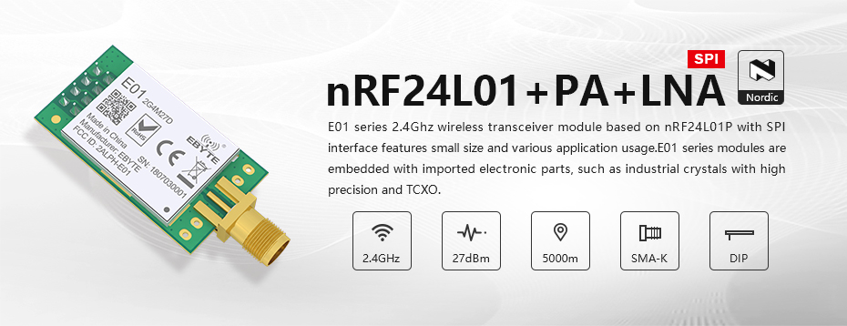
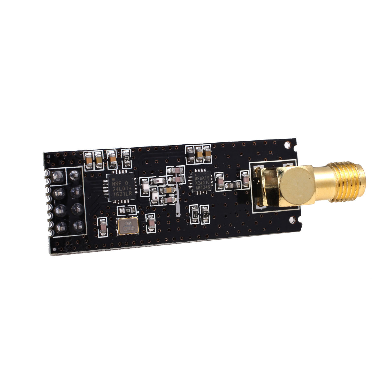
@skywatch I am using this module
and like this
-
RE: Specific register setting fo NRF24 with PA-LNA
@Yveaux I want to try solve the problem with NRF24 module with PA-LNA..
-
RE: Specific register setting fo NRF24 with PA-LNA
@mfalkvidd you right, this define don't changing the register..
I find deeper and what can i see in datasheet:and i see in RF24.h:
#define RF24_RF_SETUP (uint8_t)(( ((MY_RF24_DATARATE & 0b10 ) << 4) | ((MY_RF24_DATARATE & 0b01 ) << 3) | (MY_RF24_PA_LEVEL << 1) ) + 1) //!< RF24_RF_SETUP, +1 for Si24R1 and LNA
May be need change in this define?
UPDATE: As i see, in RF4.h used HCURR = 1:
#define RF24_RF_SETUP .. // !< RF24_RF_SETUP, +1 for Si24R1 and LNA
-
Specific register setting fo NRF24 with PA-LNA
It has long been known, that the NRF24 module with PA-LNA work strangely, if the RF24_PA_LEVEL parameter has not the RF24_PA_LOW value.
I decided to study the issue a little and found such a parameter in the registers of the NRF24 chip settings - "LNA gain":
"6.5 LNA gain
The gain in the Low Noise Amplifier (LNA) in the nRF24L01 receiver is controlled by the LNA gain setting. The LNA gain makes it possible to reduce the current consumption in RX mode with 0.8mA at the cost of 1.5dB reduction in receiver sensitivity.The LNA gain has two steps and is set by the LNA_HCURR bit in the RF_SETUP register."
(see nRF24L01 Single Chip 2.4GHz TransceiverProduct Specification)I see this setting in RF24registers.h:
#define RF24_LNA_HCURR (0)
May be here I may use "1" for module with PA-LNA?
#define RF24_LNA_HCURR (1)
-
RE: Starting my PC with a 3.3v arduino pro mini?
@kiesel Yes, you rigth - between 3.3V on mainboard and VCC of arduino!
-
RE: Starting my PC with a 3.3v arduino pro mini?
@kiesel Sorry friend, I guess I confused you a little ..
The diode is needed so that, when powered from the contacts on the motherboard with 5V, it does not damage my arduino, that's all
Have a nice weekend to! -
RE: Starting my PC with a 3.3v arduino pro mini?
@kiesel See for example this for understand the idea:
https://www.allaboutcircuits.com/technical-articles/how-to-protect-your-circuits-using-only-a-diode/ -
RE: Starting my PC with a 3.3v arduino pro mini?
@kiesel I don't undestand - why you want to use diode between 3.3V and GND?
About resistor on the mainboard side - i don't use it and all works fine -
RE: Starting my PC with a 3.3v arduino pro mini?
@kiesel Great work!
- 5V connected through diode to protect of polarity revers
- MB = Motherboard, you right
- First need to connect power button from front panel, second to connect to "Power Switch" on motherboard. This allows power on both from power button and Arduino.
You disign is absolutely working!
-
RE: Starting my PC with a 3.3v arduino pro mini?
You can use anything like this:
https://electronics.stackexchange.com/questions/129463/switch-on-computer-with-microcontroller
i am using just one PC817:
-
RE: Corrupted data from RS485 Sensor Node
What about RS485 bus topology and connection to RS485 recievers on Arduino Pro Mini module?
-
RE: Supply 230V/5V for node ? Mini Pro, NRF24L01, ams1117
@skywatch Don't worry - in my case it doesn't matter, because the plug can be inserted into the socket on both sides
-
RE: Supply 230V/5V for node ? Mini Pro, NRF24L01, ams1117
I am using the same power supply in one of my device (dimmer for aqua LED lamp)- it work good..
-
RE: Supply 230V/5V for node ? Mini Pro, NRF24L01, ams1117
Very dangerous - too small gap between AC230 and GND:
-
RE: MYSBootloader 1.3.0-beta.3
@iguaan Try to set MY_RF24_PA_LEVEL to RF24_PA_MIN on gateway then use NRF24L01+PA+LNA module - in my case the OTA begin work perfect!
-
RE: 💬 Simple compact RS485 node v2 (ATmega328 + MAX3485 + W25X40)
Most likely you are right, nevertheless, all my simple devices are working correctly, the only problem that I have encountered is a problem when flashing some controllers through the USBASP.
-
RE: 💬 Simple compact RS485 node (ATmega328 + MAX485)
@dzjr Congrats! My works on hobby is not hard because of we have nice weather too
-
RE: 💬 Simple compact RS485 node (ATmega328 + MAX485)
@dzjr This is terrible, but yesterday I received a message from PSBs.io that my order from 04/13/2020 is only sent ..
-
RE: 💬 Simple compact RS485 node (ATmega328 + MAX485)
@dzjr I am ordered a new revision of this PCB at 2020.04.13, and the order status is "in fabrication" too, don't worry.
-
RE: 💬 Simple compact RS485 node (ATmega328 + MAX485)
@dzjr I am using simple solder station like 936 with 900M-T-I iron tip, first solder the MCU and pin-headers, programm with USBASP using pads SCK, MISO, MOSI, RES, VCC ang GND, then solder other components (MAX485, resistors and capacitors).
-
RE: 💬 Simple compact RS485 node (ATmega328 + MAX485)
@dzjr Ordering PCBs you will get only pcb, without components (no matter - SMD or TH). You may use PCB assebling service like JLCPCB or other, or you may solder SMD components yourself, it is not so hard, as you can think.
-
RE: 💬 Simple compact RS485 node (ATmega328 + MAX485)
@dzjr I can upload new revision, but it still not tested in hardware, only ready to place order for PCB!
-
RE: 💬 Simple compact RS485 node (ATmega328 + MAX485)
Soon a new revision of the board with the possibility of installing memory for OTA and fix some components footprints will be ready.
-
RE: OTA not working in my current setup (CRC Error)
@VonJoost I see in serial console about the same picture - dump is 000000....
-
RE: OTA not working in my current setup (CRC Error)
May be it's help you - in my case with Winbond W25X40CL changing code in SPIFlash.h solve the problem with CRC error:
i change this:
#define SPIFLASH_BLOCKERASE_32K 0x52 //!< erase one 32K block of flash memory
on this:
#define SPIFLASH_BLOCKERASE_32K 0xD8 //!< erase one 64K block of flash memory
-
RE: ENC28J60 Ethernet gateway
@sergio-rius sorry, my mistake, missed of using RFM69 in your setup..
-
RE: ENC28J60 Ethernet gateway
@sergio-rius Pinout as described here Building an Ethernet Gateway, i am use module like this:
and my sketch on 20-Feb-2019 is:
#define MY_BAUD_RATE 9600 //#define MY_RF24_PA_LEVEL RF24_PA_MIN #undef MY_REGISTRATION_FEATURE #undef MY_CORE_COMPATIBILITY_CHECK // Enable debug prints to serial monitor #define MY_DEBUG // Enable and select radio type attached #define MY_RADIO_NRF24 //#define MY_RADIO_RFM69 // When ENC28J60 is connected we have to move CE/CSN pins for NRF radio #define MY_RF24_CE_PIN 5 #define MY_RF24_CS_PIN 6 // Enable gateway ethernet module type #define MY_GATEWAY_ENC28J60 // Gateway IP address #define MY_IP_ADDRESS 192,168,1,235 // The port to keep open on node server mode / or port to contact in client mode #define MY_PORT 5003 // Controller ip address. Enables client mode (default is "server" mode). // Also enable this if MY_USE_UDP is used and you want sensor data sent somewhere. //#define MY_CONTROLLER_IP_ADDRESS 192, 168, 178, 254 // The MAC address can be anything you want but should be unique on your network. // Newer boards have a MAC address printed on the underside of the PCB, which you can (optionally) use. // Note that most of the Ardunio examples use "DEAD BEEF FEED" for the MAC address. #define MY_MAC_ADDRESS 0xDE, 0xAD, 0xBE, 0xEF, 0xFE, 0xED // Flash leds on rx/tx/err //#define MY_LEDS_BLINKING_FEATURE // Set blinking period //#define MY_DEFAULT_LED_BLINK_PERIOD 300 // Enable inclusion mode //#define MY_INCLUSION_MODE_FEATURE // Enable Inclusion mode button on gateway //#define MY_INCLUSION_BUTTON_FEATURE // Set inclusion mode duration (in seconds) //#define MY_INCLUSION_MODE_DURATION 60 // Digital pin used for inclusion mode button //#define MY_INCLUSION_MODE_BUTTON_PIN 3 //#define MY_DEFAULT_ERR_LED_PIN 7 // Error led pin //#define MY_DEFAULT_RX_LED_PIN 8 // Receive led pin //#define MY_DEFAULT_TX_LED_PIN 9 // the PCB, on board LED #include <SPI.h> #include <UIPEthernet.h> #include <MySensors.h> void setup() { } void loop() { }
-
RE: ENC28J60 Ethernet gateway
@kimot I am use one Ethernet gateway about 2 year - work good and stable.
-
RE: 💬 Simple compact RS485 node (ATmega328 + MAX485)
Attention !!! Possible unstable work node with LP2950 LDO!
I am don't understand yet, but one of the node don't work by powering of 12V using LP2950CZ-50 LDO.
Temporary i am using AMS1117 on this node, and order HT7550-1 for testing. -
RE: 💬 Simple compact RS485 node (ATmega328 + MAX485)
Example of usage RS485 node: Light control module
-
RE: Powering NRF24l01+ with DC-DC Module Abaisseur Regulateur Tension Step Down
I am use switching DC-DC the same as you to get 5V from 12V and LDO XC6206 to power NRF24 module - all work good.
-
RE: Powering NRF24l01+ with DC-DC Module Abaisseur Regulateur Tension Step Down
As i see, two first module is impulse, but third - linear?
-
RE: Newbie wants to do everything wired
@feanor-anglin said in Newbie wants to do everything wired:
Star topology is not recommended to use with RS485, but it is not that it certainly won't work. You have to test it.
I know about it, but I hope that with a speed of 9600 and a small cable length it will work ..
-
RE: Newbie wants to do everything wired
@tweaker still not - not enough time to assemble additional nodes..
I have encountered problems that are still not clear to me when assembling the second board - it does not want to connect to the gateway.
I checked everything that is possible, but I haven’t found the reasons yet..
I will plan To assemble one more test node .. -
RE: Newbie wants to do everything wired
@tweaker said in Newbie wants to do everything wired:
@cabat : Thanks for sharing. When do you plan to connect more nodes? How long will be the cables?
In fact now i have 2 nodes, but one of then only for testing purpose, sending temp every 15 seconds.
The cable is about 10-15 meters. -
RE: Newbie wants to do everything wired
@tweaker
I'm also plan to use star topology, but still i build just one node
Use 9600 baud rate, and i don't have delay on my experience on this day. -
RE: Newbie wants to do everything wired
@feanor-anglin said in Newbie wants to do everything wired:
If you like it, please feel free to contact me. We've made some significant progress, which is not published yet.
I am also intresting in implementation of RS485 in my MySensors network, and i like yor hardware and use some of your ideas in my project Simple compact RS485 node (ATmega328 + MAX485) ,
-
RE: 💬 Simple compact RS485 node (ATmega328 + MAX485)
UPDATE: Tested in hardware now.
-
RE: 💬 Simple compact RF24 node (ATmega328 + NRF24)
Update: PCB with NRF24 standart version tested in hardware.
-
RE: 💬 Simple compact RF24 node (ATmega328 + NRF24)
@yveaux Sorry, i don't test the range of nodes - plan to use in the 2 floor house of 60 meters.
But you opinion is correct, this design is compromise of size, pins count and range degradate.
This is prototype, work good about 1 year:
-
RE: 💬 Simple compact RF24 node (ATmega328 + NRF24)
Update status "Work in progress" (add info about tested in hardware configuration, add example of usage).
-
RE: Regulators needed
@dbemowsk
I used LP2950-5.0 in one node when feeding from 12v - about 3 months everything works quite stably. -
RE: 💬 jModule
@ted Hello! Can you share the Eagle file of your version of pcb? I mean this one: http://dirtypcbs.com/view.php?share=19651&accesskey=2e5e31a83bf6fe21510c3bc438e12df7