Navigation

    • Register
    • Login
    • OpenHardware.io
    • Categories
    • Recent
    • Tags
    • Popular
    1. Home
    2. Dwalt
    3. Best
    • Profile
    • Following
    • Followers
    • Topics
    • Posts
    • Best
    • Groups

    Best posts made by Dwalt

    • Experimenting with cheap 433mhz gadgets

      I originally found MySensors while looking for a way to control 433mhz outlets with my Vera. Being frugal, I did not want to spend money on RFXtrx or similar device to control cheap outlets. My first sensor node was a nano with a 433mhz transmitter which controls several plugin outlets around my house. I later modified it to include the receiver which I used to intercept my neighbors weather station data. Unexpectedly, his weather station disappeared a few months ago and I stopped getting his data. I don't know if he took it down or it fell off his roof or was stolen. I waited a week and then sadly deleted the child devices on my Vera. Recently I decided to move on and find more uses for the 433mhz node, especially the reciever and stumbled upon some really cheap Chinese gadgets on Ebay/Ali and thought I would share some of what I found out.

      First of all, the cheap Rx/Tx pair listed in the MySensors store is really cheap ($0.69?) but are not very good. The transmitter operates fine but the receiver is terrible. Both have acceptable range but I found I could not use the receiver with most of the available libraries due to the very poor signal/noise ratio. I had to 'sniff' most signals down to their binary level and re-encode this mess into a sketch for retransmission. Reception was also hit or miss. I recently upgraded to the superheterodyne Tx/Rx modules and like magic, all the libraries suddenly work, range seems slightly better but most noticeably, missed transmissions are gone.

      I also recently bought this cheap rf LED strip controller for ~$1.80.
      IMG_20151029_171728.jpg

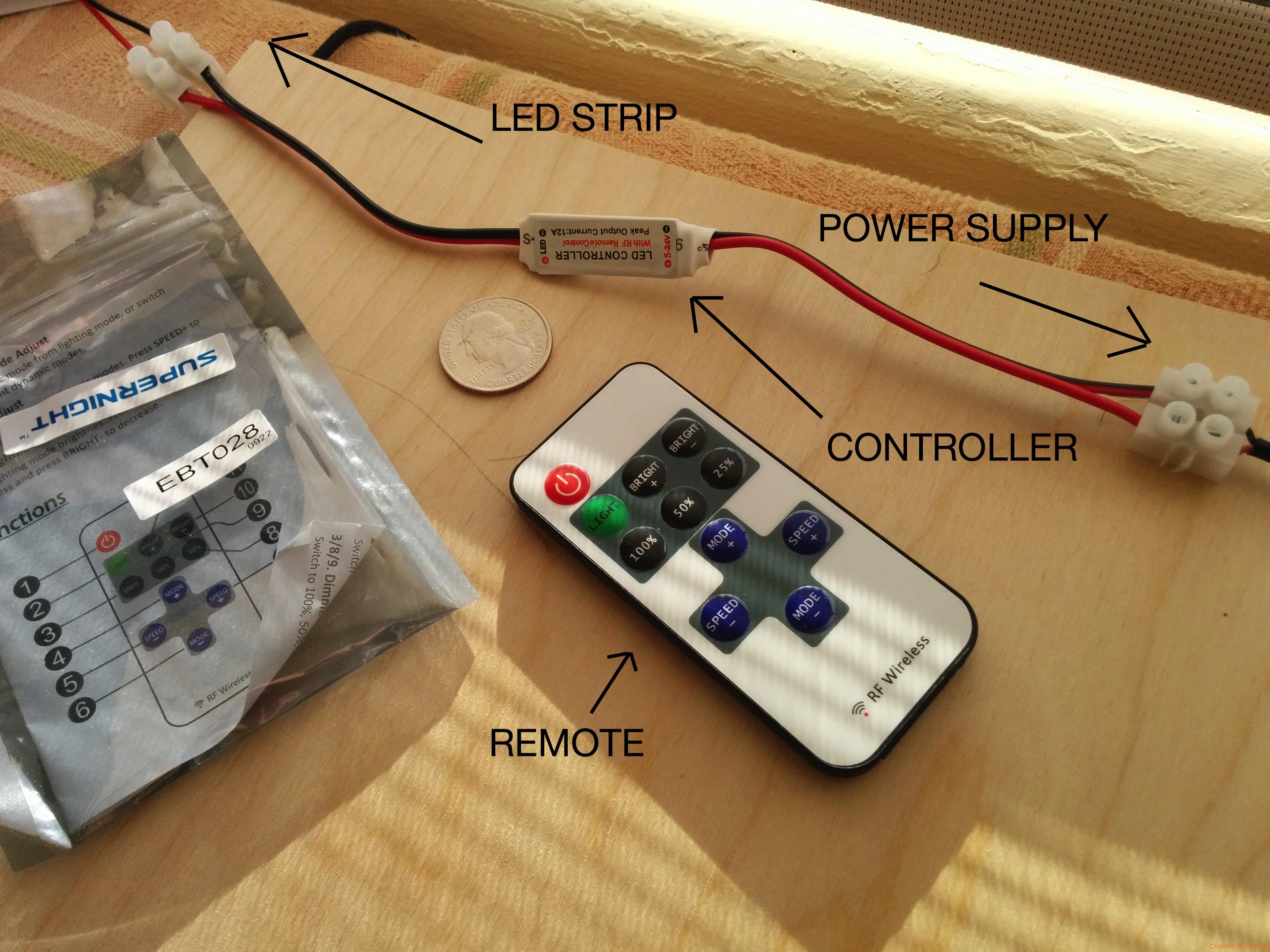
      Surprisingly it actually works but the included remote has a range of only a few meters. So I sniffed the codes with the RCSwitch Library and wrote a sketch to test it with MySensors. Primarily I wanted to explore the dimming functionality and ran into a few problems. The unit dims the LED strip in very noticeable steps which cause the light to blink slightly as it dims, not very elegant but not a deal breaker (19 steps from 5-100%). The device is not individually addressable so if you have multiples, they will all follow the same commands. The fatal flaw of this device is the power on/off command is toggled which means the same code turns it off as turns it back on. I ran this for about 2 days and it missed a power on command (or a power off, I don't know). Once it got out of phase, it had to be manually corrected with the remote or remain out of phase until another missed command.

      Another cheap chinese gadget I tested was this learning remote.
      IMG_20151029_171647.jpg

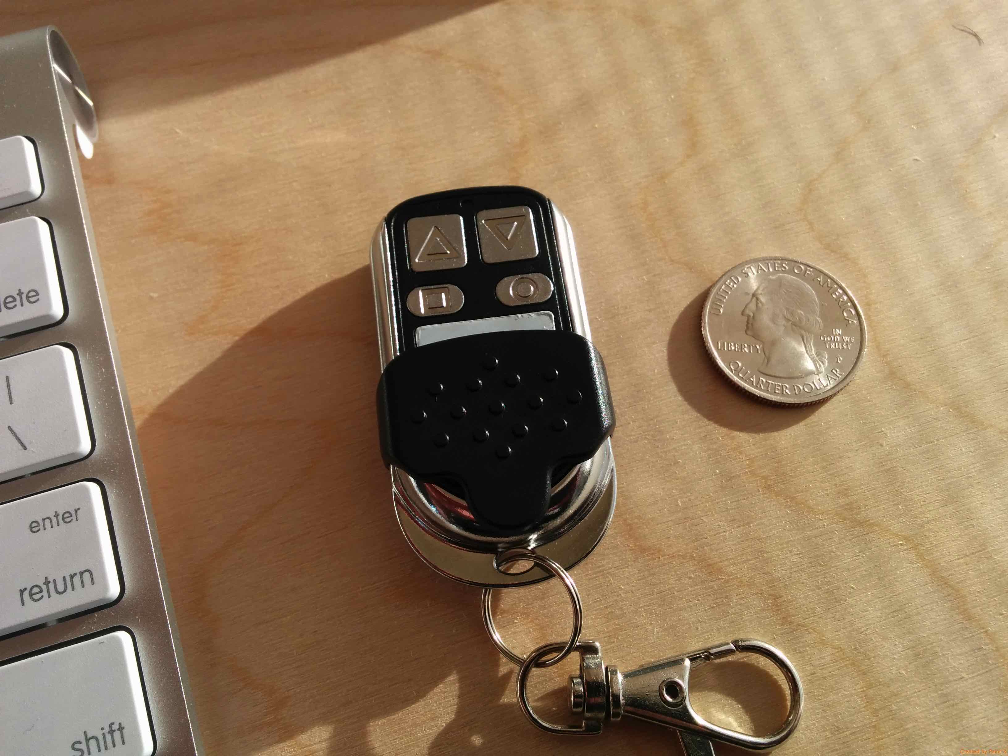
      It has four buttons which can each be programed with any 433mhz code you want and store the code in memory to retransmit. I made up some codes which were similar in structure and pulse length as my 433mhz outlets use, made a simple sketch to broadcast the codes so I could 'program' the keychain remote. With 4 unique codes in the keychain, I modified my 433mhz sensor node sketch to include a scene controller sketch which toggles 4 scenes on and off (I used AWI's toggle scene controller sketch for the pertinent code-fu.). Unlike the rf LED controller, the scene state is stored in the arduino which makes it more dependable. Perhaps not as reliable as nrf , z-wave or zigbee, but for a $2 portable scene controller....not bad.

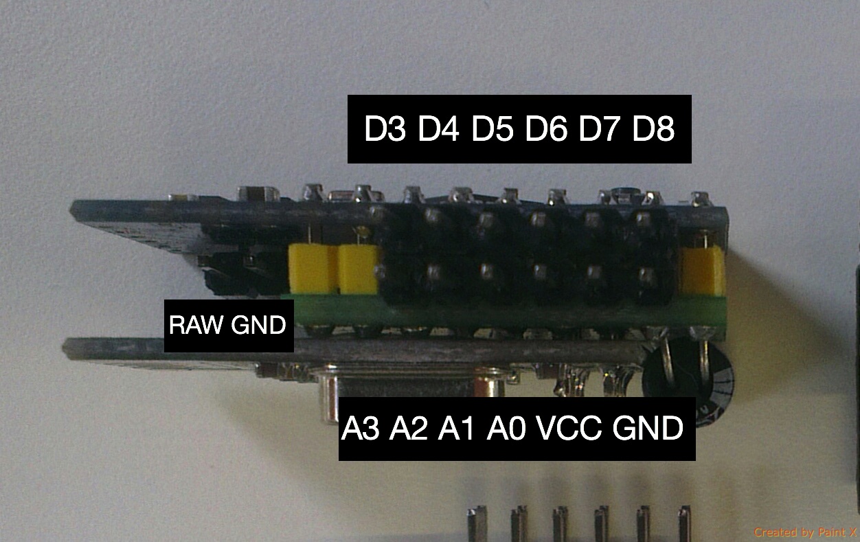
      Attached is my sketch for toggling on an off four 433mhz outlets and a scene controller. The hardware is simple. I have a nano on mains power with the superheterodyne Rx on pin #2 and the Tx on pin #3. Both are power by 5V separately from the nano and have 17cm antenna soldered on.

      #include <MySensor.h>
      #include <SPI.h>
      #include <EEPROM.h>  
      #include <MyTransportNRF24.h>
      #include <MyHwATMega328.h>
      #include <RemoteReceiver.h>
      #include <RemoteTransmitter.h>
      #include <InterruptChain.h>
      
      
      #define NUMBER_OF_OUTLETS 4
      #define SN "433mhz Bridge"
      #define SV "1.3"
      
      const byte SC_CHILD_ID = 0 ;
      unsigned long receivedCode = 0 ;
      int key=0;
      
      // Setup arrays with the unique button codes sniffed using ShowReceivedCode.ino from the RemoteSwitch library 
      // These are outgoing codes, one array for 'switch on' and one for 'switch off'
      long rfCodeON [] = {492004, 492022, 491914, 491752};
      long rfCodeOFF [] = {492006, 492024, 491916, 491754};
      
      int pulse = 185;  //The average pulse length of the codes, needed for the RemoteTransmitter sendCode function
      
      // Setup an array of the expected incoming codes from the KeyFob transmitter
      unsigned long sceneCode [] = {491266, 491268, 491275, 491277}; 
      byte keyState[4]  ;
      
      MySensor gw;
      MyMessage scene_on(SC_CHILD_ID, V_SCENE_ON);
      MyMessage scene_off(SC_CHILD_ID, V_SCENE_OFF);
      
      
      void setup() { 
        
       Serial.begin(115200); 
         
       gw.begin(incomingMessage, 15, true);
       gw.sendSketchInfo(SN, SV);
      
       //  Create a child device for each outlet
       for (int sensor=1; sensor<=NUMBER_OF_OUTLETS; sensor++){
       gw.present(sensor, S_LIGHT);
       delay(2);
       }
       
       //  Create a child device for the scene controller and load last Scenestates from EEPROM
       gw.present(SC_CHILD_ID, S_SCENE_CONTROLLER);
       for (int i=0 ; i < sizeof(sceneCode); i++){
              keyState[i] = gw.loadState(i) ;         
              }
      
      // Initialize receiver on interrupt 0 (= digital pin 2), calls the function "incomingCode"
      RemoteReceiver::init(0, 2, incomingCode);
      InterruptChain::addInterruptCallback(0, RemoteReceiver::interruptHandler);
      }
      
      void loop() {
       gw.process();
       
      }
      
      // Function for when a code has been received from rF KeyFob transmitter
        void incomingCode(unsigned long receivedCode, unsigned int period) {
      //Disable the 433mhz Reciever to prevent additional interupts from incoming signals 
        RemoteReceiver::disable();
      //Enable interupts to allow gw.wait  
        interrupts();
      // Print the received code.
        Serial.print("Code: ");
        Serial.print(receivedCode);
        Serial.print(", period: ");
        Serial.print(period);
        Serial.println("us.");
      
      // check the recieved code against the array of expected codes
          for (byte i = 0 ; i < 4 ; i++){    
              if(receivedCode == (sceneCode[i])) key=i+1;// set key if a valid code is recieved
              }
      // Print the scene number        
        Serial.print("Scene #: ");
        Serial.println(key);   
          
          if (key > 0){                                   
              boolean keyVal = !gw.loadState(key-1);      // use lastState from EEPROM and toggle
              gw.saveState(key-1, keyVal);                // save new state to EEPROM
              if (keyVal) gw.send(scene_on.set(key-1));   // set the Scene On or Off
              else gw.send(scene_off.set(key-1));
             gw.wait(500);
              key = 0;                                    // reset key
              receivedCode = 0 ;                          // reset code
              RemoteReceiver::enable();                   // turn 433mhz receiver back on
         }
      }
      
      
      // Function for when a command has been received from gateway
        void incomingMessage(const MyMessage &message) 
      {
       {
        if (message.type==V_LIGHT) 
        {
          Serial.print("Outlet #: ");
          Serial.println(message.sensor);
          Serial.print("Command: ");
          Serial.println(message.getBool());
      // Turn off 433mhz receiver to prevent reception of outgoing 433mhz broadcast   
          RemoteReceiver::disable();
      //  Send out the code stored in the arrays based on which child id and command is recieved.  
      //  Syntax is (pin 3, code to be transmitted, pulse length, transmit repetitions ~2^3 or 8 times)
          RemoteTransmitter::sendCode(3,message.getBool()? rfCodeON[message.sensor - 1]: rfCodeOFF[message.sensor - 1], pulse, 3);
        }
        delay(50);
       }
      // Turn the 433mhz Receiver back on 
      RemoteReceiver::enable();
      }    
        
      
      posted in My Project
      Dwalt
      Dwalt
    • My generic room-senser (Sensebender with Motion and Light)

      I have been trying to make a generic sensor to deploy throughout my house to provide variables which my home automation can work from. The primary data streams I was looking for are temp, motion sensing and light level. From these three, a lot of automation can be created. The Sensebender is the perfect platform to build from - small and designed for battery power. I added a ambient light phototransistor and a low power panasonic PIR and used these cheap housings from ALIExpress. I drove the phototransistor from a digital pin (D7) so it could be powered on and off every time thru the loop and powered the whole thing from a CR123 battery.

      The sketch was based upon the Sensebender Micro sketch with minor additions for the PIR and light level sensor. The PIR is setup on the interrupt on D3 and the light sensor follows the same timer schedule as the Si7021.

      // Default sensor sketch for Sensebender Micro module
      // Act as a temperature / humidity sensor by default.
      //
      // If A0 is held low while powering on, it will enter testmode, which verifies all on-board peripherals
      // 
      // Battery voltage is repported as child sensorId 199, as well as battery percentage (Internal message)
      
      
      #include <MySensor.h>
      #include <Wire.h>
      #include <SI7021.h>
      #include <SPI.h>
      #include <SPIFlash.h>
      #include <EEPROM.h>  
      #include <sha204_lib_return_codes.h>
      #include <sha204_library.h>
      
      // Define a static node address, remove if you want auto address assignment
      //#define NODE_ADDRESS   3
      
      #define RELEASE "1.0"
      
      // Child sensor ID's
      #define CHILD_ID_TEMP  1
      #define CHILD_ID_HUM   2
      #define CHILD_ID_PIR   3
      #define CHILD_ID_LIGHT  4
      #define CHILD_ID_BATT  199
      
      // How many milli seconds between each measurement
      #define MEASURE_INTERVAL 60000
      
      // FORCE_TRANSMIT_INTERVAL, this number of times of wakeup, the sensor is forced to report all values to the controller
      #define FORCE_TRANSMIT_INTERVAL 30 
      
      // When MEASURE_INTERVAL is 60000 and FORCE_TRANSMIT_INTERVAL is 30, we force a transmission every 30 minutes.
      // Between the forced transmissions a tranmission will only occur if the measured value differs from the previous measurement
      
      //Pin definitions
      #define TEST_PIN       A0
      #define LED_PIN        A2
      #define PIR_SENSOR_DIGITAL 3
      #define LIGHT_PIN A1
      #define ATSHA204_PIN   17 // A3
      
      const int sha204Pin = ATSHA204_PIN;
      atsha204Class sha204(sha204Pin);
      
      SI7021 humiditySensor;
      SPIFlash flash(8, 0x1F65);
      
      MySensor gw;
      
      // Sensor messages
      MyMessage msgHum(CHILD_ID_HUM, V_HUM);
      MyMessage msgTemp(CHILD_ID_TEMP, V_TEMP);
      MyMessage msgPir(CHILD_ID_PIR, V_TRIPPED);
      MyMessage msgLight(CHILD_ID_LIGHT, V_LIGHT_LEVEL);
      MyMessage msgBattery(CHILD_ID_BATT, V_VOLTAGE);
      
      // Global settings
      int measureCount = 0;
      boolean isMetric = true;
      
      
      // Storage of old measurements
      float lastTemperature = -100;
      int lastHumidity = -100;
      int lastLightLevel = -1;
      long lastBattery = -100;
      boolean lastTrippedState;
      
      bool highfreq = true;
      
      void setup() {
      
        pinMode(LED_PIN, OUTPUT);
        digitalWrite(LED_PIN, LOW);
      
        pinMode(PIR_SENSOR_DIGITAL, INPUT);
        digitalWrite(PIR_SENSOR_DIGITAL, HIGH);
      
        pinMode(7, OUTPUT);  // โ€œpower pinโ€ for Light Sensor
        digitalWrite(7, LOW);  // switch power off
      
        Serial.begin(115200);
        Serial.print(F("Sensebender Micro FW "));
        Serial.print(RELEASE);
        Serial.flush();
      
        // First check if we should boot into test mode
      
        pinMode(TEST_PIN,INPUT);
        digitalWrite(TEST_PIN, HIGH); // Enable pullup
        if (!digitalRead(TEST_PIN)) testMode();
      
        digitalWrite(TEST_PIN,LOW);
        digitalWrite(LED_PIN, HIGH); 
      
      #ifdef NODE_ADDRESS
        gw.begin(NULL, NODE_ADDRESS, false);
      #else
        gw.begin(NULL,AUTO,false);
      #endif
      
        digitalWrite(LED_PIN, LOW);
      
        humiditySensor.begin();
        Serial.flush();
        Serial.println(F(" - Online!"));
        gw.sendSketchInfo("Sensebender 4-Way", RELEASE);
        
        gw.present(CHILD_ID_TEMP,S_TEMP);
        gw.present(CHILD_ID_HUM,S_HUM);
        gw.present(CHILD_ID_PIR, S_MOTION);
        gw.present(CHILD_ID_LIGHT, S_LIGHT_LEVEL);
        
        isMetric = gw.getConfig().isMetric;
        Serial.print("isMetric: "); Serial.println(isMetric);
      
      }
      
      
      // Main loop function
      void loop() {
        measureCount ++;
        bool forceTransmit = false;
      
        // When we wake up the 5th time after power on, switch to 1Mhz clock
        // This allows us to print debug messages on startup (as serial port is dependend on oscilator settings).
        if ((measureCount == 5) && highfreq) switchClock(1<<CLKPS2); // Switch to 1Mhz for the reminder of the sketch, save power.
        
        if (measureCount > FORCE_TRANSMIT_INTERVAL) { // force a transmission
          forceTransmit = true; 
          measureCount = 0;
        }
      
        gw.process();
        sendBattLevel(forceTransmit);
        digitalWrite(7, HIGH); // switch power on to LDR
        sendTempHumidityMeasurements(forceTransmit);
        sendLight(forceTransmit);
        digitalWrite(7, LOW); // switch power off to LDR
        sendPir();
        
        gw.sleep(PIR_SENSOR_DIGITAL - 2, CHANGE, MEASURE_INTERVAL);  
      }
      
      /*
       * Sends temperature and humidity from Si7021 sensor
       *
       * Parameters
       * - force : Forces transmission of a value (even if it's the same as previous measurement)
       */
      void sendTempHumidityMeasurements(bool force)
      {
        if (force) {
          lastHumidity = -100;
          lastTemperature = -100;
        }
        
        si7021_env data = humiditySensor.getHumidityAndTemperature();
        
        float temperature = (isMetric ? data.celsiusHundredths : data.fahrenheitHundredths) / 100.0;
          
        int humidity = data.humidityPercent;
      
        if ((lastTemperature != temperature) | (lastHumidity != humidity)) {
          Serial.print("T: ");Serial.println(temperature);
          Serial.print("H: ");Serial.println(humidity);
          
          gw.send(msgTemp.set(temperature,1));
          gw.send(msgHum.set(humidity));
          lastTemperature = temperature;
          lastHumidity = humidity;
        }
      }
      
      /*   
       *  Sends Motion alert on interupt
       */
      
      void sendPir() // Get value of PIR
      {
        boolean tripped = digitalRead(PIR_SENSOR_DIGITAL) == HIGH; // Get value of PIR
        if (tripped != lastTrippedState)
        {  
          Serial.println(tripped? "tripped" : "not tripped");
          gw.send(msgPir.set(tripped?"1":"0"));  // Send tripped value to gw//
        }
        lastTrippedState = tripped;


        }
        
      
      /*
       * Sends Ambient Light Sensor information
       * 
       * Parameters
       * - force : Forces transmission of a value
       */
      
      void sendLight(bool force) // Get light level
      {
        if (force) lastLightLevel = -1;
        int lightLevel =  (analogRead(LIGHT_PIN)) / 10.23;
        if (lightLevel != lastLightLevel) {
         gw.send(msgLight.set(lightLevel));
          lastLightLevel = lightLevel;
        }
        Serial.print("Light: ");
        Serial.println(lightLevel);
      }
      
      /*
       * Sends battery information (both voltage, and battery percentage)
       *
       * Parameters
       * - force : Forces transmission of a value
       */
      void sendBattLevel(bool force)
      {
        if (force) lastBattery = -1;
        long vcc = readVcc();
        if (vcc != lastBattery) {
          lastBattery = vcc;
          // Calculate percentage
      
          vcc = vcc - 1900; // subtract 1.9V from vcc, as this is the lowest voltage we will operate at
          
          long percent = vcc / 14.0;
          gw.sendBatteryLevel(percent);
        }
      }
      
      long readVcc() {
        // Read 1.1V reference against AVcc
        // set the reference to Vcc and the measurement to the internal 1.1V reference
        #if defined(__AVR_ATmega32U4__) || defined(__AVR_ATmega1280__) || defined(__AVR_ATmega2560__)
          ADMUX = _BV(REFS0) | _BV(MUX4) | _BV(MUX3) | _BV(MUX2) | _BV(MUX1);
        #elif defined (__AVR_ATtiny24__) || defined(__AVR_ATtiny44__) || defined(__AVR_ATtiny84__)
          ADMUX = _BV(MUX5) | _BV(MUX0);
        #elif defined (__AVR_ATtiny25__) || defined(__AVR_ATtiny45__) || defined(__AVR_ATtiny85__)
          ADcdMUX = _BV(MUX3) | _BV(MUX2);
        #else
          ADMUX = _BV(REFS0) | _BV(MUX3) | _BV(MUX2) | _BV(MUX1);
        #endif  
       
        delay(2); // Wait for Vref to settle
        ADCSRA |= _BV(ADSC); // Start conversion
        while (bit_is_set(ADCSRA,ADSC)); // measuring
       
        uint8_t low  = ADCL; // must read ADCL first - it then locks ADCH  
        uint8_t high = ADCH; // unlocks both
       
        long result = (high<<8) | low;
       
        result = 1125300L / result; // Calculate Vcc (in mV); 1125300 = 1.1*1023*1000
        return result; // Vcc in millivolts
      }
      
      void switchClock(unsigned char clk)
      {
        cli();
        
        CLKPR = 1<<CLKPCE; // Set CLKPCE to enable clk switching
        CLKPR = clk;  
        sei();
        highfreq = false;
      }
      
      
      // Verify all peripherals, and signal via the LED if any problems.
      void testMode()
      {
        uint8_t rx_buffer[SHA204_RSP_SIZE_MAX];
        uint8_t ret_code;
        byte tests = 0;
        
        digitalWrite(LED_PIN, HIGH); // Turn on LED.
        Serial.println(F(" - TestMode"));
        Serial.println(F("Testing peripherals!"));
        Serial.flush();
        Serial.print(F("-> SI7021 : ")); 
        Serial.flush();
        
        if (humiditySensor.begin()) 
        {
          Serial.println(F("ok!"));
          tests ++;
        }
        else
        {
          Serial.println(F("failed!"));
        }
        Serial.flush();
      
        Serial.print(F("-> Flash : "));
        Serial.flush();
        if (flash.initialize())
        {
          Serial.println(F("ok!"));
          tests ++;
        }
        else
        {
          Serial.println(F("failed!"));
        }
        Serial.flush();
      
        
        Serial.print(F("-> SHA204 : "));
        ret_code = sha204.sha204c_wakeup(rx_buffer);
        Serial.flush();
        if (ret_code != SHA204_SUCCESS)
        {
          Serial.print(F("Failed to wake device. Response: ")); Serial.println(ret_code, HEX);
        }
        Serial.flush();
        if (ret_code == SHA204_SUCCESS)
        {
          ret_code = sha204.getSerialNumber(rx_buffer);
          if (ret_code != SHA204_SUCCESS)
          {
            Serial.print(F("Failed to obtain device serial number. Response: ")); Serial.println(ret_code, HEX);
          }
          else
          {
            Serial.print(F("Ok (serial : "));
            for (int i=0; i<9; i++)
            {
              if (rx_buffer[i] < 0x10)
              {
                Serial.print('0'); // Because Serial.print does not 0-pad HEX
              }
              Serial.print(rx_buffer[i], HEX);
            }
            Serial.println(")");
            tests ++;
          }
      
        }
        Serial.flush();
      
        Serial.println(F("Test finished"));
        
        if (tests == 3) 
        {
          Serial.println(F("Selftest ok!"));
          while (1) // Blink OK pattern!
          {
            digitalWrite(LED_PIN, HIGH);
            delay(200);
            digitalWrite(LED_PIN, LOW);
            delay(200);
          }
        }
        else 
        {
          Serial.println(F("----> Selftest failed!"));
          while (1) // Blink FAILED pattern! Rappidly blinking..
          {
          }
        }  
      }


      Photos of the assembly -
      The parts:
      IMG_20150622_115335.jpg
      The board with radio, resistors and FTDI header:
      IMG_20150622_131215.jpg
      The board connected to the battery and sensors (the sensors were wire-wrapped utilizing the 'whiskers' from the resistors):
      IMG_20150622_151216.jpg
      The finished enclosures (I made a few):
      IMG_20150622_152033.jpg
      IMG_20150622_153431.jpg

      They work pretty well but after a few days I have noticed some peculiarities which I hope the forum could assist with:

      1. The Si7021 is VERY sensitive and as a result, the sensors update every minute or two and have not yet slept more than 2-3 minutes. Is there an easy way to fix this in the code so they only transmit every .3 or .5 degree temperature change?

      2. The Panasonic PIRs I am using do not have trim pots to adjust their 'standby-after-alert' time and return to detecting motion after 2.5 seconds which leads to a lot of radio traffic to the gateway when someone is in the room. I thought about 'detaching' the interrupt after alert and 'reattaching' on the next run thru the loop. The would give it up to 60 seconds of standby which would work for my needs but I do not know exactly how to go about this and if it would cause more problems than solve.

      3. I oriented the headers over the blank part of the board (over the stylish logo). They are on the opposite side of the board from the radio but are located directly in line with the antenna (see photo 2). Is this a bad idea? I have not observed any transmission problems or at least I do not think I have...

      posted in My Project
      Dwalt
      Dwalt
    • RE: Detecting if a persons is laying in his/her bed

      I made a few homemade pressure switches to solve a similar problem with presence detection while watching TV. Occasionally my living room PIR would not sense people if they were very still and lights would turn off when a scene would fire on my controller. I built several pressure switches out of cardboard, aluminum tape, thin foam (for spacers) and scrap phone cable and placed them under seat cushions. I use them as simple binary switches and incorporated this sketch within a multisensor I have under a end table.

      Sorry for the bad photos:
      couch1.jpg

      couch2.jpg

      couch3.jpg

      The wire runs to either side of the switch and is installed between layers of aluminum tape. This tape is made of aluminum and is conductive. I found it at a hardware store, it is used for installing air duct. When someone sits on the cushion, the switch compresses and both sides make contact and trip the arduino. I made a larger one for placing under a door mat to let me know when the dog wanted back in the house. Below is a picture during construction. Foam strips were placed between the rows of alum tape and the two side were stacked together and placed under the door mat. When the dog would sit on the mat, it triggered a 'door/window sensor' in Vera and I had a PLEG condition which flashed a Hue bulb in the living room. It did not last long after getting wet but the dog liked it while it worked.๐Ÿ˜„

      couch4.jpg

      posted in Hardware
      Dwalt
      Dwalt
    • RE: Sensor for Vallox DigitSE RS485 ventilation system with integration into FHEM.

      @Heinz said:

      BTW finding an appropriate housing for your sensors is not very easy. Housings should be nice and fit into their environment...

      Hiding sensors in plain sight:

      1-IMG_20150210_012436.jpg

      Book2.jpg
      One of my "Book-Sensors":
      1-IMG_20150210_012729.jpg

      posted in My Project
      Dwalt
      Dwalt
    • RE: Mysensors on ESP8266- ESP01?

      @Elfnoir There are a various tutorials for using the Arduino IDE for flashing sketches onto ESP8266 on the internet. I don't remember which I used originally. Firstly, you need to add the ESP8266 to the IDE through the board manager. Secondly, Unlike the Arduino, the ESP needs to be set into bootloader mode to load a sketch. Whereas the Arduino bootloader looks for an incoming upload when the chip is reset (For most boards, the IDE automatically resets the chip when you begin an upload). The ESP needs its GPIO-0 drawn to ground when it is reset to enter bootloader mode so it can be a little trickier to wire up

      I used the development branch of MySensors to create ESP nodes using the GatewayESP8266.ino sketch. I just remove the

      #define MY_RADIO_NRF24
      

      and any bits about inclusion buttons and then add my particular parts to the setup, presentation and loop parts of the sketch depending on my attached sensors. There are more tricky details to the process but it isn't much different than creating a Arduino/nRf sensor node. I agree a tutorial is in order but the process is still evolving that is why it is the "development " branch.

      I use some of the ESP-12, the Huzzah from adafruit and i have several commercial products with imbedded ESP8266 which i reflashed and MySensorizedโ„ข. I will try this weekend to document a project in detail. Too busy today.

      posted in Hardware
      Dwalt
      Dwalt
    • RE: ๐Ÿ’ฌ jModule

      Ahh, I see now. The side facing pins are mapped as follows:

      0_1457124334179_JMOD PINOUT.jpg

      posted in OpenHardware.io
      Dwalt
      Dwalt
    • RE: Where can I get more information on the project 'Mood Light' ??

      Small world! I made a similar light using a Phillips Hue bulb in the same IKEA lamp.

      I use it for notifications from tasker and Vera.

      posted in My Project
      Dwalt
      Dwalt
    • RE: What's the best PIR sensor?

      @NeverDie said:

      So, at least for an outdoor motion sensor, it might turn out to be a very easy modification requiring little effort.

      Finding a tear down on somebody's blog would certainly help inform the purchase....

      Here is a review of a similar solar light.

      (http://www.ebay.com/itm/12-LED-Solar-Powered-PIR-Motion-Sensor-Light-Outdoor-Garden-Security-Wall-Light-/251959451412?hash=item3aa9f41f14).

      A lot of space inside for arduino, radio and additional sensors. Plus it is made of plastic which is better for radio. So you have a weatherproof housing with solar panel, battery, charging circuit and PIR already built in.

      posted in Hardware
      Dwalt
      Dwalt
    • RE: Looooong range wireless...

      Here is an antenna mod which get 1km+ range from the nrf24.

      posted in General Discussion
      Dwalt
      Dwalt
    • RE: Remote Panel

      @pete1450 Something like this?. http://forum.mysensors.org/topic/2413/ir-record-and-playback-module

      posted in Vera
      Dwalt
      Dwalt
    • RE: Recommendation: power supply

      @ToniA The Sensebender was designed with battery power in mind. I have several with attached PIR and LDR running near to 7 months off a single CR123 and they all report battery near 90%. Powering off AC would be possible with addition of voltage regulator but would be a waste of a beautiful low powered design.

      posted in Hardware
      Dwalt
      Dwalt
    • RE: Complete Beginner with MySensors - questions about relays, MQTT and OpenHAB

      @HenryWhite You do not need to use MQTT for your gateway, you can use the serial or ethernet gateways as well. You may find them easier to get started with MySensors.

      posted in General Discussion
      Dwalt
      Dwalt
    • RE: Connecting serial gateway to vera edge usb

      @leovz

      Are you using a nano clone? Check if it has a FTDI branded USB chip on the bottom or a CH340 chip for usb/serial communications. Veras do not have the drivers for the CH chip and unfortunately I do not think you can install the drivers within Vera.

      posted in Vera
      Dwalt
      Dwalt
    • RE: 433mhz outlet

      @jribera

      Below is a simple sketch I use for controlling 433Mhz outlets (sockets) with MySensors. I am not very good at coding but this sketch worked for my setup, I assume it could be improved.

      https://codebender.cc/sketch:67827

      I created a sensor node with a nano connected to a 433Mhz transmitter which is on mains power so the sensor is always "listening". I used the 5V from the nano to power the 433 transmitter but I believe it could run off 3.3V. The node controls four cheap 433Mhz outlets. I only have four but this sketch could be expanded to control many more. These outlets do not give feedback so the sketch is somewhat simple in that regard. These outlets use the PT2262 encoder which is common but may not work with your sockets. If you have a remote with your sockets, your can take it apart to see what encoder is used.

      -Dwalt

      posted in Troubleshooting
      Dwalt
      Dwalt
    • RE: Recommendation: power supply

      @ToniA This thread is veering off topic but to clarify my comment, powering the Sensebender off of mains runs contrary to the design of the board. For your example, this board would be a more efficient design - a compact relay board designed for mains powering, ~$9.50 US. It still requires a 5V power supply ๐Ÿ˜‰ .

      posted in Hardware
      Dwalt
      Dwalt
    • RE: Hum temp rain sensor help

      @floris I think it may have to do with the brackets { } in your loop. You have a open bracket { for your first " if" statement to check the rain and it does not appear to close } until after your "sleep" function at the bottom of the entire loop. This would cause the hum and temp readings (and sleep) to be skipped until the "if" statement is satisfied.

      posted in Troubleshooting
      Dwalt
      Dwalt
    • RE: Iboard - Cheap Single board Ethernet Arduino with Radio

      @5546dug It sounds like everything is working correctly with the iBoard itself, did you configure the MySensors plugin for the IP of the GW? When I switched from serial GW to iBoard, I did not delete the plugin, I just entered the IP Addy in the plugin settings and boom, everything worked, and zero hiccups with the GW ever since.

      posted in Hardware
      Dwalt
      Dwalt
    • RE: [SOLVED] 2 X nrf24l01+pa+lna with RF24_PA_MAX

      @Oitzu Yes, now my network will ride eternal!

      Actually, my brother saw the modification and asked if I was trying to prevent the NSA from intercepting my humidity readings. Hmmm, maybe a secondary benefit...

      rob-tinfoil-hat-compressed.jpg

      posted in Troubleshooting
      Dwalt
      Dwalt
    • RE: Mysensors on ESP8266- ESP01?

      @Elfnoir

      I don't know about the limitations of the ESP01 as I don't have any, but I use several other ESP8266 models as stand alone sensor or actuator nodes by flashing MySensors sketches on them, and join them to my network like any other Arduino/Nrf24L01 based node. I use Vera and for a single sensor node, Vera creates two devices - one for the node and one for the sensor or actuator. One difference between a regular MySensors device and the ESP is that the node device is esentially its own gateway as it uses WiFi to communicate straight to the controller and does not communicate thru my Ethernet GW like the NRf nodes. It shows up in Vera like the original plugin.

      There are other ways to join ESP8266s to a controller but I prefer MySensors as the protocols and device types are already established through the plugin so there is no extra lua or http coding required.

      posted in Hardware
      Dwalt
      Dwalt
    • RE: sensebender sketch with door sensor help needed

      @BigDog What kind of door sensor do you have? Normally Open (NO) or Normally Closed(NC)? Adding a Reed Switch is fairly straightforward using the available interrupt on D3 and folding in the code from the binary switch example. Keeping it low power, however depends on your hardware.

      Most reed switches sold as window/door sensors are NO, which means the circuit is closed when the magnet is present. In the case of a door or window, this means the circuit is closed when the door or window are in their secure state, closed, and current is flowing. This is because window/door sensors were developed for wired alarm systems and having the current constant provided a additional level of security to detect tampering or wire breaks. For battery powered sensors, you cannot afford this constant current. A NC reed switch is preferable which means no current is flowing when the magnet is nearby (actually a little current flows with most NC switches but still acceptable for battery sensors, most off the shelf zwave wireless window/door sensors are NC).

      One problem with this system is most Asian vendors randomly switch the NC and NO terminology and you never know what you are buying. I can't speak for European vendors, they use that silly metric system.

      posted in Troubleshooting
      Dwalt
      Dwalt
    • RE: Homini Complete Room Sensor Module?

      @Samuel235
      I was under the assumption you intended this module to be always 'listening' to allow a controller to set it to night mode or 'disarm'. If so, battery power will be tricky. In addition, PIRs require a period of stabilization when powered on, often up to 30 seconds to calibrate sensor field of view background.

      posted in Hardware
      Dwalt
      Dwalt
    • RE: Bad radio performance (small reach)

      @Tronix The construction of your home will alter the radios performance. I have concrete floors and the radio signal does not travel well through the concrete. Interior walls made of wallboard and wood do not interfere as much. 20-60 meters is possible with clear line of sight.

      Any sensor that is mains powered is a potential repeater.

      posted in Troubleshooting
      Dwalt
      Dwalt
    • RE: Figaro TGS5042 Carbon Monoxide Sensor & Op Amp

      @Samuel235 said:

      ...does this count as the conductive mat

      Conductive foam is impregnated with carbon and is generally black in color and denser than styrofoam. The pink foam common in packaging is 'anti-static' but not conductive. Methinks that is simple packaging styrofoam. As a side note, conductive foam is very useful for making pressure sensors, never throw it away.

      posted in Hardware
      Dwalt
      Dwalt
    • RE: Kitchen Node .. Messy Code..

      @mrcage Do your temp sensors show up at all (as child devices) to your controller or are they just not sending data?

      You changed one define:

      int numSensors=3; 
      

      I don't know if it is necessary, you call for a device count later in setup.

      What hardware are you using? Mega? You have typical 'interrupt' driven devices, door and motion...but you have your one wire bus on pin3 (interrupt 1) and define your motion interrupt as interrupt 2 (pin 4 minus 2 is 2)? I would suggest putting door and motion on pins 2 & 3, set up as interrupt functions and don't poll them continuously in the loop. I would also remove the sleep function since you are expecting incoming messages for your RGB strip and use millis to establish how often you check the Dallas sensors.

      posted in Troubleshooting
      Dwalt
      Dwalt
    • RE: Senserbender Humidity Value Error

      @hdrider465

      Are you using the ESP8266 gateway? If so, the problem may be with the gateway, not the sensebender. Something about 8bit to 32bit conversion. See here.

      posted in Troubleshooting
      Dwalt
      Dwalt
    • RE: Sensebender micro as serial gateway: transmit data?

      @nsom67

      Are you interested in using a sensebender as a serial gateway or just interested in adding temp and humidity sensors to your gateway? The latter option is possible under the development branch by adding the coding bits regarding the temp/hum sensor to the Serial GW sketch. I would recommend against, however, as it could interfere with the gateway's primary function (e.g. missing messages) while processing sensor routines.

      The sensebender was designed for battery operation and it's use as a powered gateway would nullify the design innovations and would most likely require additional power regulation for stable operation. The only benefit, as I can see, would be the built-in ATSHA204 for security.

      posted in Troubleshooting
      Dwalt
      Dwalt