Skip to content
  • MySensors
  • OpenHardware.io
  • Categories
  • Recent
  • Tags
  • Popular
Skins
  • Light
  • Brite
  • Cerulean
  • Cosmo
  • Flatly
  • Journal
  • Litera
  • Lumen
  • Lux
  • Materia
  • Minty
  • Morph
  • Pulse
  • Sandstone
  • Simplex
  • Sketchy
  • Spacelab
  • United
  • Yeti
  • Zephyr
  • Dark
  • Cyborg
  • Darkly
  • Quartz
  • Slate
  • Solar
  • Superhero
  • Vapor

  • Default (No Skin)
  • No Skin
Collapse
Brand Logo
L

LastSamurai

@LastSamurai
Hardware Contributor
About
Posts
503
Topics
49
Shares
0
Groups
1
Followers
1
Following
0

Posts

Recent Best Controversial

  • Coin cell based small sensor node / handsoldering smd parts
    L LastSamurai

    As promised here is my own try at creating a sensor platform based on mysensors. I have several nodes up and running for some weeks/months without problems at the moment :)
    Battery life with CR2032 depends on the kind of sensor used but should be 1,5 + years on everyone.
    Love to hear some feedback and/or suggestions on what kind of sensor to add next.

    I think I will add some door/window sensors next

    link text

    Hardware

  • PCB Boards for MySensors
    L LastSamurai

    @MikeF Dirtypcbs rarely takes more than 3-4 weeks for me too (in germany), but you are right, a local source would be great. There are several producers here too, but for everyone I know prices are at least 5 times what the chinese take.
    If you (or someone else) finds a european service that produces prototypes (1-3 boards) for less than 15€ per piece please share it! Could come in very handy when developing new boards.

    Hardware

  • Finalizing my very simple gateway
    L LastSamurai

    I am currently planing to update my mysensors setup (as making it more "professional", less wires) and build a new one somewhere else. For that I was looking for an easy/simple to build serial gateway and could not really find one. There are some great ones here like sensebender but these use hard to solder components and generally just more than I need.

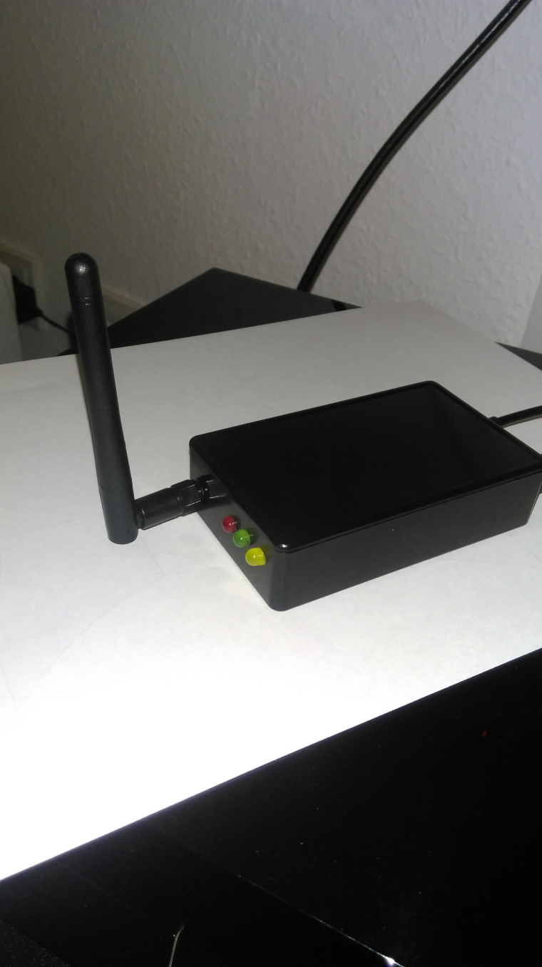
    Here is my idea for a simple and relatively cheap gateway. It fits into a small and cheap box from aliexpress and contains an arduino nano, a nrf pa lna and a micro usb breakout for power.
    Hardware signing can be added with the atsha and I also added pins for 433Mhz sender and receiver. These could either be used on the gateway directly or using the same pcb with a normal nrf as a seperate node.

    I will finalize the pcb in the next days and send it to manufactoring. Any feedback from you guys until then? Anything you would add? Any errors you are seeing?

    Gateway.pdf

    PS Here is a picture of my prototype 0_1491944739483_OH433Gateway.jpg

    Hardware

  • Low Power?
    L LastSamurai

    Yes use sleep() ;) . Take a look at the api.

    General Discussion

  • MySensors shield and RGBW Controller
    L LastSamurai

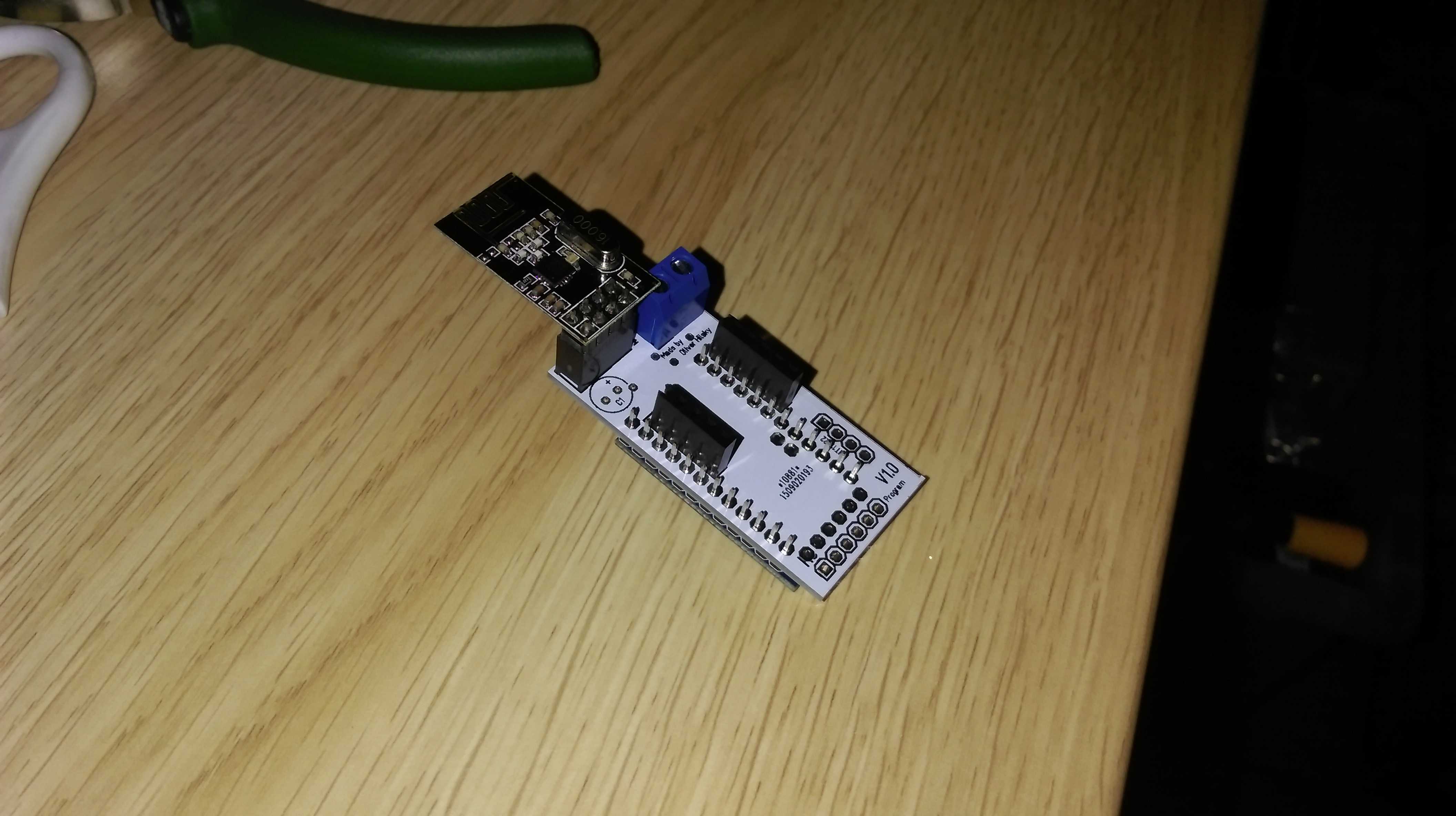
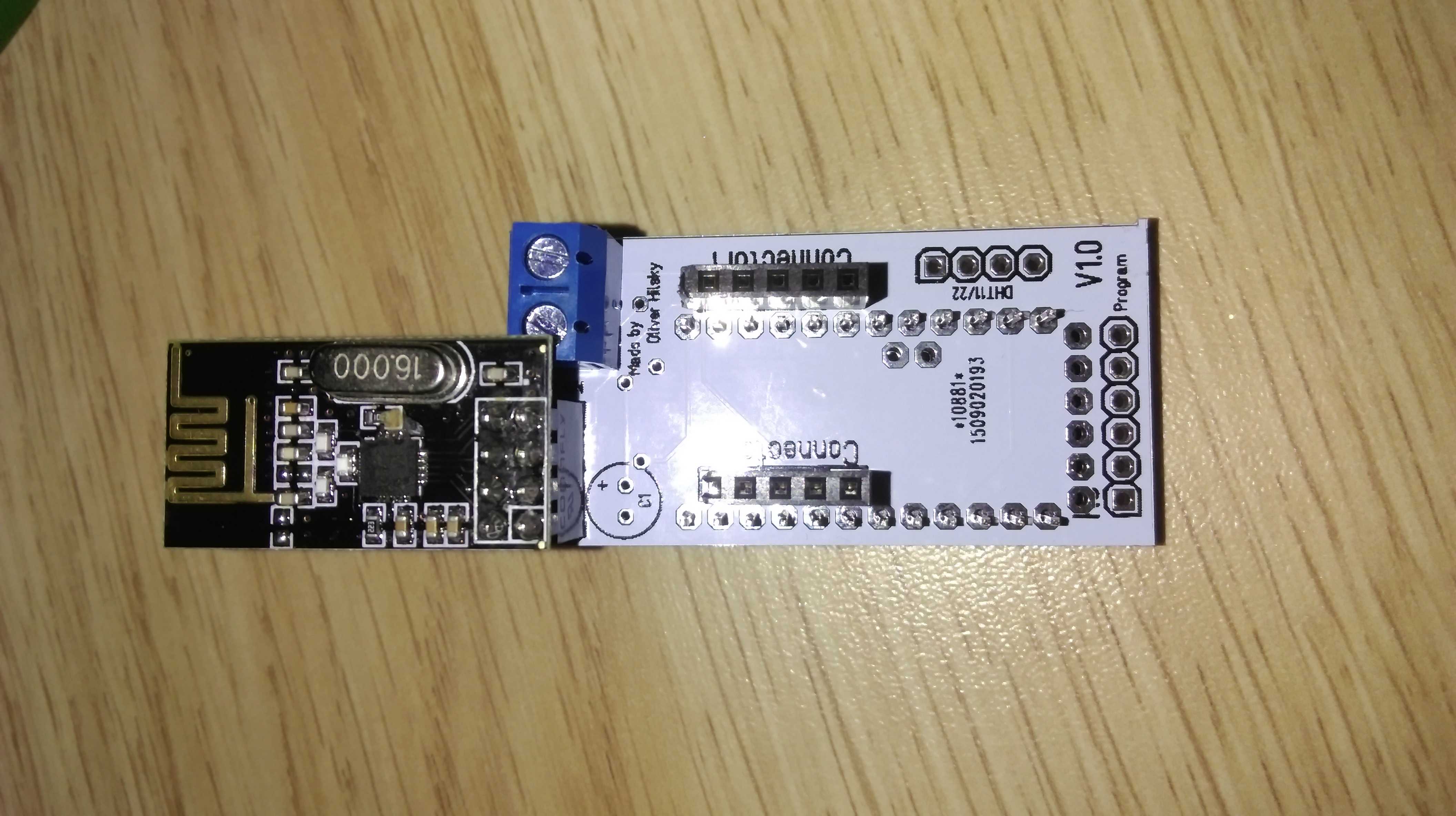
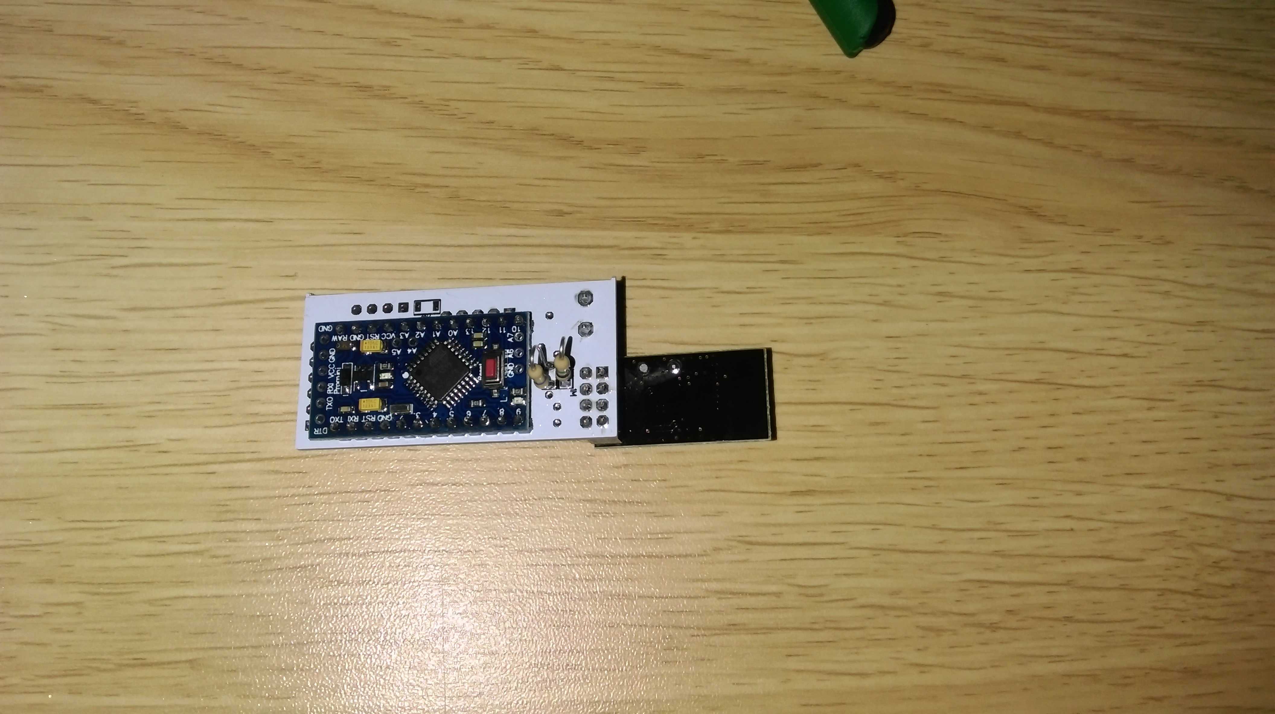
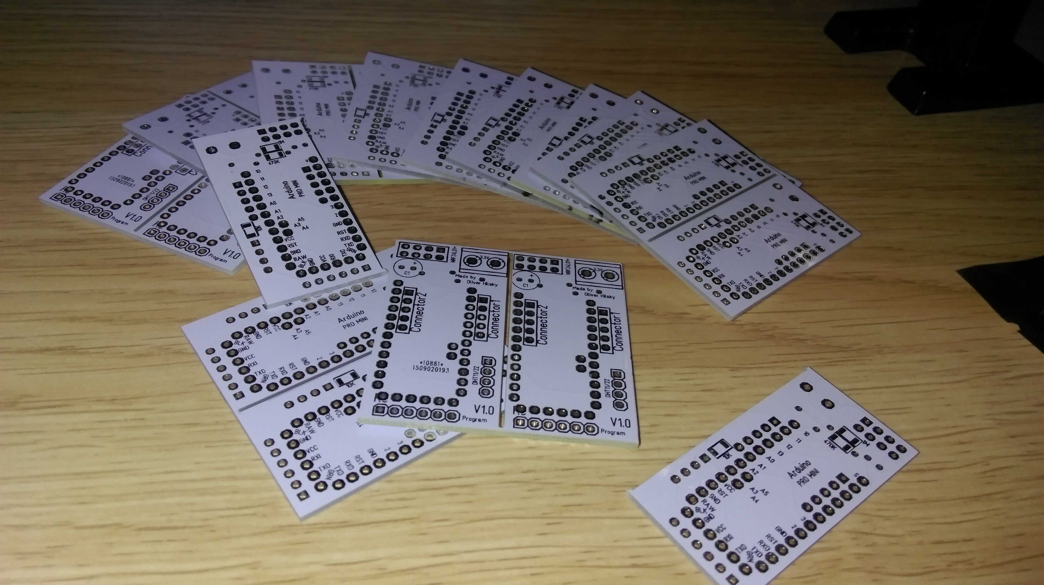
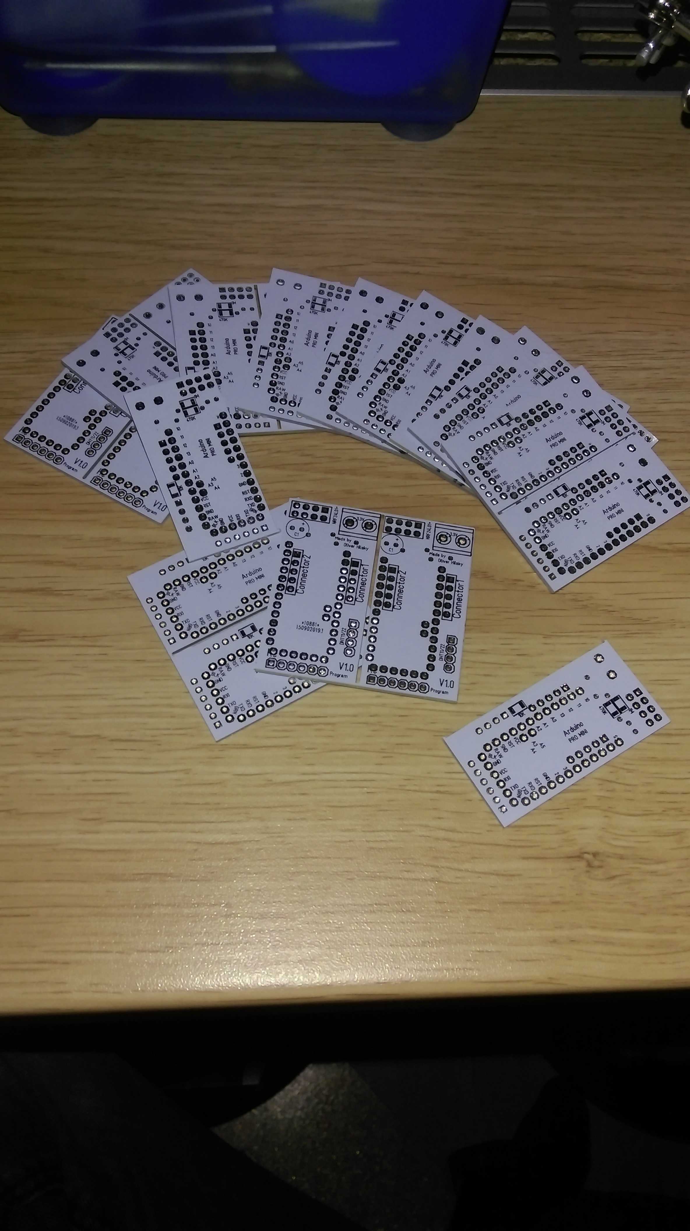
    Yeah :sparkles: my PCBs from dirtypcbs finally arrived! So I instantly had to open the package and I must say: these pcbs are really well made (for that price). Here are pics. As you can see I designed them so that 2 fit on one 5x5cm pcb. So I have gotten myself 24 potential "smart" sensors now :smiley:
    I haven't gotten all components yet for multiple sensors but I started with one test sensor anyways. It has through hole resistors instead of some smd ones, no capacitor and no DHT22 yet. But once I get the components I will add them on the prototype. For now it's up and running with a demo sketch that just sends random values.
    And everything seems to be working nicely. Yeah^^

    Next step is to finalize the components and test some other components as arduino shield like components on the two pin headers I added for that one. And I already found some small things that I could still improve.

    Once that's all done I will finalize the RGBW ones and send them of for production.

    Love to hear your feedback and tipps guys!

    PS can I somehow add these pictures as thumbnails? They are quite big...
    IMAG0013.jpg IMAG0012.jpg IMAG0010.jpg IMAG0009.jpg IMAG0008.jpg

    Hardware

  • Are folks here happy with Domoticz?
    L LastSamurai

    I am actually happy with domoticz. I have used it for about a year and its main advantage for was that it's very easy to learn and to use. Recently I discovered dzVents (which is now integrated in the domoticz beta) that allows for easier and more complex scripts. For now I was able to do anything I wanted in domoticz.
    The UI isn't perfect (although openhaps is way worse imho) but it gets the job done.

    I also tried to use openhab (2) earlier but thats a totally different beast. You can do awesome stuff but it's REALLY hard to get started. The new ui in openhab 2 looks great but its still a weird mix of using text files and the ui.
    HA also looks great but I haven't tried it yet.

    So overall I would start with domoticz and switch later if you are missing any features.

    PS also domoticz updates (at least for features related to mysensors) seem to be implemented pretty slow. I have opened several tickets in their git where the answer was mostly: implemented on you own ;) Which is fine (I dont pay them afterall) but other systems seem to be way more active.

    Domoticz

  • MySensors shield and RGBW Controller
    L LastSamurai

    Just a short update: I now have 5 of these controllers controlling different led strips in my apartment. They are all working without a problem (some of them for nearly half a year now).
    I did some small updates to the code (which you can get via github) and will try to update the pcb later to fix that one annoying error with the mosfets.

    Hardware

  • 💬 Ikea Molgan Hack
    L LastSamurai

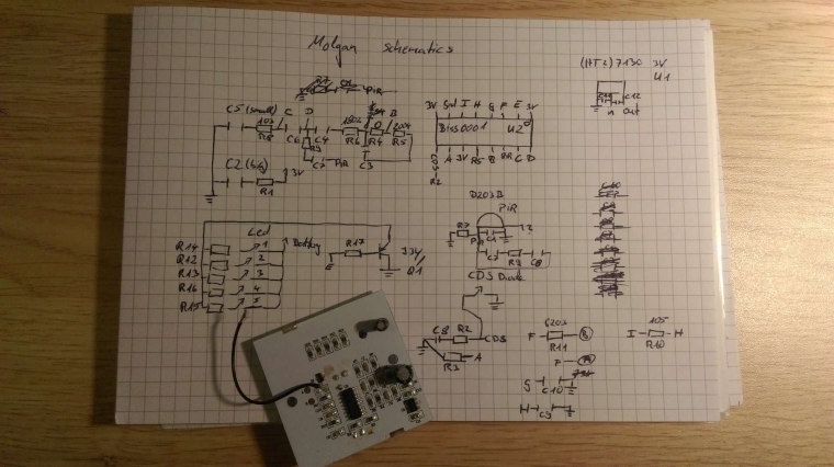
    I just spend an hour tracing the routes on the pcb. I am pretty sure I missed some (and there might be some errors) but here are my results for now. Ill redo them with KiCad later. Can someone measure the capacitors? They are unlabeled.

    0_1488836803988_MolganSchematicsFullHD.jpg

    OpenHardware.io motion molgan hack pir mysensors ikea

  • RGBW setup
    L LastSamurai

    Hi, great to hear that someone else is using my project too. Perhaps we can get it to work for you too :)

    First of all your mosfets should work too, I was using IRLZ44N mosfets too for my prototypes (although some people in the forum had problems with them I think).
    All your leds turn on because the standard setting (when the node doesn't receive anything else) is to turn on every channel to 100 of 255.

    byte values[4] = {100, 100, 100, 100};
    byte target_values[4] = {100, 100, 100, 100}; 
    

    Change that part if you don't want this behaviour.

    The important part of your code for changing colors is the incomingMessage(const MyMessage &message) function. In your logs I am never seeing any serial output from that function. So I guess you never get any new messages with new values?! Try to find out why that method never gets called.
    I haven't worked with mysensors 2.0 yet so it might be a problem with the conversion or just with your radio setup. With 1.5 and my node it works well (I have 5 nodes running atm).

    Troubleshooting

  • Slim Node Si7021 sensor example
    L LastSamurai

    @rsachoc Yes, I actually just tried it out and its working.
    Here is my code for now (just for testing):
    I basically just switched libraries

    /* Sketch with Si7021 and battery monitoring.
    by m26872, 20151109 
    Changed by LastSamurai
    15052016
    */
    #include <MySensor.h>  
    #include <Wire.h>
    #include <SPI.h>
    #include <SparkFunHTU21D.h>
    #include <RunningAverage.h>
    
    //#define DEBUG
    
    #ifdef DEBUG
    #define DEBUG_SERIAL(x) Serial.begin(x)
    #define DEBUG_PRINT(x) Serial.print(x)
    #define DEBUG_PRINTLN(x) Serial.println(x)
    #else
    #define DEBUG_SERIAL(x)
    #define DEBUG_PRINT(x) 
    #define DEBUG_PRINTLN(x) 
    #endif
    
    #define NODE_ID 100             // <<<<<<<<<<<<<<<<<<<<<<<<<<<   Enter Node_ID
    #define CHILD_ID_TEMP 0
    #define CHILD_ID_HUM 1
    // #define SLEEP_TIME 15000 // 15s for DEBUG
    #define SLEEP_TIME 300000   // 5 min
    #define FORCE_TRANSMIT_CYCLE 36  // 5min*12=1/hour, 5min*36=1/3hour 
    #define BATTERY_REPORT_CYCLE 2016   // Once per 5min   =>   12*24*7 = 2016 (one report/week)
    #define VMIN 1900
    #define VMAX 3300
    #define HUMI_TRANSMIT_THRESHOLD 3.0  // THRESHOLD tells how much the value should have changed since last time it was transmitted.
    #define TEMP_TRANSMIT_THRESHOLD 0.5
    #define AVERAGES 2
    
    int batteryReportCounter = BATTERY_REPORT_CYCLE - 1;  // to make it report the first time.
    int measureCount = 0;
    float lastTemperature = -100;
    int lastHumidity = -100;
    
    RunningAverage raHum(AVERAGES);
    HTU21D humiditySensor;
    
    MySensor gw;
    MyMessage msgTemp(CHILD_ID_TEMP,V_TEMP); // Initialize temperature message
    MyMessage msgHum(CHILD_ID_HUM,V_HUM);
    
    void setup() {
      DEBUG_SERIAL(9600);    // <<<<<<<<<<<<<<<<<<<<<<<<<< Note BAUD_RATE in MySensors.h
      DEBUG_PRINTLN("Serial started");
      
      DEBUG_PRINT("Voltage: ");
      DEBUG_PRINT(readVcc()); 
      DEBUG_PRINTLN(" mV");
    
      delay(500);
      DEBUG_PRINT("Internal temp: ");
      DEBUG_PRINT(GetInternalTemp()); // Probably not calibrated. Just to print something.
      DEBUG_PRINTLN(" *C");
    
      delay(500); // Allow time for radio if power useed as reset
      gw.begin(NULL, NODE_ID);
      gw.sendSketchInfo("TempHumTest2", "1.0 17052016"); 
      gw.present(CHILD_ID_TEMP, S_TEMP);   // Present sensor to controller
      gw.present(CHILD_ID_HUM, S_HUM);
      DEBUG_PRINT("Node and "); DEBUG_PRINTLN("2 children presented.");
      
      raHum.clear();
      humiditySensor.begin();  
    }
    
    void loop() { 
    
      measureCount ++;
      batteryReportCounter ++;
      bool forceTransmit = false;
      
      if (measureCount > FORCE_TRANSMIT_CYCLE) {
        forceTransmit = true; 
      }
      sendTempHumidityMeasurements(forceTransmit);
    /*
      // Read and print internal temp
      float temperature0 = static_cast<float>(static_cast<int>((GetInternalTemp()+0.5) * 10.)) / 10.;
      DEBUG_PRINT("Internal Temp: "); DEBUG_PRINT(temperature0); DEBUG_PRINTLN(" *C");        
    */
      // Check battery
      if (batteryReportCounter >= BATTERY_REPORT_CYCLE) {
        long batteryVolt = readVcc();
        DEBUG_PRINT("Battery voltage: "); DEBUG_PRINT(batteryVolt); DEBUG_PRINTLN(" mV");
        uint8_t batteryPcnt = constrain(map(batteryVolt,VMIN,VMAX,0,100),0,255);   
        DEBUG_PRINT("Battery percent: "); DEBUG_PRINT(batteryPcnt); DEBUG_PRINTLN(" %");
        gw.sendBatteryLevel(batteryPcnt);
        batteryReportCounter = 0;
      }
      
      gw.sleep(SLEEP_TIME);
    }
    
    // function for reading Vcc by reading 1.1V reference against AVcc. Based from http://provideyourown.com/2012/secret-arduino-voltmeter-measure-battery-voltage/
    // To calibrate reading replace 1125300L with scale_constant = internal1.1Ref * 1023 * 1000, where internal1.1Ref = 1.1 * Vcc1 (per voltmeter) / Vcc2 (per readVcc() function) 
    long readVcc() {
      // set the reference to Vcc and the measurement to the internal 1.1V reference
      ADMUX = _BV(REFS0) | _BV(MUX3) | _BV(MUX2) | _BV(MUX1);
      delay(2); // Wait for Vref to settle
      ADCSRA |= _BV(ADSC); // Start conversion
      while (bit_is_set(ADCSRA,ADSC)); // measuring
      uint8_t low  = ADCL; // must read ADCL first - it then locks ADCH  
      uint8_t high = ADCH; // unlocks both
      long result = (high<<8) | low;
      result = 1125300L / result; // Calculate Vcc (in mV); 1125300 = 1.1*1023*1000
      return result; // Vcc in millivolts
    }
    // function for reading internal temp. From http://playground.arduino.cc/Main/InternalTemperatureSensor 
    double GetInternalTemp(void) {  // (Both double and float are 4 byte in most arduino implementation)
      unsigned int wADC;
      double t;
      // The internal temperature has to be used with the internal reference of 1.1V. Channel 8 can not be selected with the analogRead function yet.
      ADMUX = (_BV(REFS1) | _BV(REFS0) | _BV(MUX3));   // Set the internal reference and mux.
      ADCSRA |= _BV(ADEN);  // enable the ADC
      delay(20);            // wait for voltages to become stable.
      ADCSRA |= _BV(ADSC);  // Start the ADC
      while (bit_is_set(ADCSRA,ADSC));   // Detect end-of-conversion
      wADC = ADCW;   // Reading register "ADCW" takes care of how to read ADCL and ADCH.
      t = (wADC - 88.0 ) / 1.0;   // The default offset is 324.31.
      return (t);   // The returned temperature in degrees Celcius.
    }
    
    /*********************************************
     * * Sends temperature and humidity from Si7021 sensor
     * Parameters
     * - force : Forces transmission of a value (even if it's the same as previous measurement)
     *********************************************/
    void sendTempHumidityMeasurements(bool force) {
      bool tx = force;
      
      float temperature = humiditySensor.readTemperature();
      DEBUG_PRINT("T: ");DEBUG_PRINTLN(temperature);
    
      float diffTemp = abs(lastTemperature - temperature);
      DEBUG_PRINT(F("TempDiff :"));DEBUG_PRINTLN(diffTemp);
    
      if (diffTemp > TEMP_TRANSMIT_THRESHOLD || tx) {
        gw.send(msgTemp.set(temperature,1));
        lastTemperature = temperature;
        measureCount = 0;
        DEBUG_PRINTLN("T sent!");
      }
      
      int humidity = humiditySensor.readHumidity();
      DEBUG_PRINT("H: ");DEBUG_PRINTLN(humidity);
    
      raHum.addValue(humidity);
      humidity = raHum.getAverage();  // MA sample imply reasonable fast sample frequency
      float diffHum = abs(lastHumidity - humidity);
      DEBUG_PRINT(F("HumDiff  :"));DEBUG_PRINTLN(diffHum); 
    
      if (diffHum > HUMI_TRANSMIT_THRESHOLD || tx) {
        gw.send(msgHum.set(humidity));
        lastHumidity = humidity;
        measureCount = 0;
        DEBUG_PRINTLN("H sent!");
      }
    
    }
    
    My Project

  • 💬 FOTA (Wireless Programming)
    L LastSamurai

    Short question from me: my mysensors network is set up with domoticz as a controller on a raspberry pi. I need to upgrade all my nodes to Version 2 of mysensors soon and want to enable wireless programming while I am at it. As far as I understand I do need to use MYSController to update a node, which seems to be a windows only program. Any way I can still use that with my linux based (raspi) network?

    Announcements wireless update over the air sensebender fota firmware over the air wireless programming

  • 💬 OH MySensors RGBW Controller
    L LastSamurai

    @pepson I wont do it because my networks is using NRFs but the kicad files are online, you could just get those and only change the radio part.

    OpenHardware.io mysensors pcb rgbw controller

  • Connecting a sensor to pc with usb
    L LastSamurai

    Yes you can. Enable debugging (should be default I think) and/or add some output lines in your code and get a usb to serial converter. Connect that one the the RX/TX/GND pins on your sensor and to the usb port of your pc. Or just use something like an arduino uno for your first tests.

    Troubleshooting

  • Office plant monitoring
    L LastSamurai

    Thanks! I will (later) and post the results here.

    My Project

  • MySensors shield and RGBW Controller
    L LastSamurai

    Hey,

    I am currently working on getting some sensors set up at my place using mySensors. I really love the project, and how easy it is to build (most) sensors. Once I got the prototype running I need "professional" sensors though, which are easy to assemble, still cheap and can fit inside a small box of some kind.
    I am planning to use a cheap pcb manufacterer like dirtypcbs.com, so the max size of the pcb is 5x5cm. This also goes well with the box part. I already got some battery holders, so all I need is the arduino + nrf + sensor on one board. Thats why I created my first design, a "motherboard"/shield which contains and arduino pro mini (3.3V) the NRF, a battery sensor and some small stuff. Also breakout pins for programming and an extra one for serial communication. The DHT11/22 can directly be placed on the pcb (because thats my most common sensor). Others sensors can be easily plucked into 2 connectors on the board as another shield. This makes it flexible but also easy to use with most kind of sensors. Power is an external part. I plan to use 3.3V wall power supplies or batteries, so no parts needed on the pcb. Didn't want to make it too complicated.
    The design is also only 25*50mm, so you can get two of them out of a cheap pcb.

    I am also planning to control lots of RGB(W) leds. Thats why I designed another pcb holding the same arduino pro mini + NRF combination, but also 4 mosfets for the different channels and a LM2596 buck converter module from ebay, which allows me to drive the whole thing directly from the 12 (or more)V power supply for the leds.

    I am thankfull for any comments or ideas how to optimize this and any errors you may find. I am planning to order them soon.

    Hardware

  • 💬 OH MySensors RGBW Controller
    L LastSamurai

    A zip with the gerber files. The version 1.3 that I used is already in their store though: http://dirtypcbs.com/store/designer/details/7078/867/mysensors-rgbw-controller-v1-3

    OpenHardware.io mysensors pcb rgbw controller

  • can´t upload my sketches anymore!!!
    L LastSamurai

    Perhaps you could also add a short description how you solved it before this gets closed. Might safe someone the time later on.

    Troubleshooting

  • Mini motion detector based on Biltema PIR LED
    L LastSamurai

    Nice project! Although I don't know biltema (doesn't exist in germany I guess) there is a similar project for an IKEA lamp somewhere here in the forum, if you need some ideas.

    My Project

  • MySensors shield and RGBW Controller
    L LastSamurai

    I finally found the time to update my RGBW control pcb and circuit. I just ordered the new version if you want to try them out.
    This time I used kiCad and will upload the new files later (and hopefully finally create the openHhardware.io project too).
    I switched to smd parts for mosfets, voltage regulator, resistors and one cap. I also fixed the wrong pinout for the mosfets and switched the CE pin to pin 4 of the pro mini so that now four real pwm pins can be used to control the RGBW outputs.

    Hardware

  • 💬 OH Mini-Multi-use Sensor Platform
    L LastSamurai

    @mfalkvidd Ups, right there is no BOM yet. I will have to add that. Wanted to do a new version with a cap parallel to the CR2032 anyways. Most components are marked on the PCB though if you need it now.
    And hek is right, that is exactly the pir I used. These cheap PIR kept going crazy after some weeks of usage though. Currently I am testing the molgan (ikea) conversion :)

    OpenHardware.io mysensors motion temperature & humidity sensor
  • Login

  • Don't have an account? Register

  • Login or register to search.
  • First post
    Last post
0
  • MySensors
  • OpenHardware.io
  • Categories
  • Recent
  • Tags
  • Popular