@hexenmeister on top of explaining where can I get the nrf radio library file for eagle ?
Posts made by mainali
-
RE: Motion detector with measurement of light intensity, temperature and humidity in the flush box.
-
RE: Long Term Data Retention and Graphing
I am building my own controller running on raspi with mysql as database so planning to integrate charts and graphs can give user a interactive view of the sensor data.
-
RE: [security] Introducing signing support to MySensors
Thanks a lot for all the Information
-
RE: [security] Introducing signing support to MySensors
I had this concerned from beginning. I will sound like a noon, but I am working on building a custom controller with loads of user configurable interface. For sake of my understanding is there any diagram or video or any resource regarding how to interface the ATSHA204A with arduino @Anticimex .
If there is something like that it will be of a great help. I am going to post a video soon of my work in progress app which controls the devices. I am also working on a scenario where someone can use the normal switches(existing ones) to operate the device and app will update accordingly. Still making way through the ACK part and the hops as I am using Ruby to do all the work -
RE: First sensor having radio issues
I am also trying something similar and I get fail in the serial monitor for all the relays I have connected. But after that everything works fine.
-
RE: State of the physical switch
I don't want to take out the panels which are holding the switches, max I can do is replace the switch with a Two Way switch, I planned on using ACS712 to sense the current and process the data accordingly in arduino to send a message to my controller but adding a current sensor to each and every switch seems to be a cumbersome process, Is there anything better then the way I am thinking.
Note: Removing the current switches completely is out of question at least for me case
-
RE: State of the physical switch
@jendrush said:
@mainali I've changed my two way switch to one way. So i can control my light with phisical button, and also by app.
Can you explain further what do you mean actually.
-
State of the physical switch
I am trying to control the switches in my house I am building my own controller to have all the flexibility that I desire. I am able to control the devices attached to the switches.
The problem is I want the control to be parallel, from app as well as the normal switch which are already present. I have replaced the switch with Two Way switch to achieve this, but I am not able to figure out the state of the physical switch. Is there a way I can know if someone activated a device from physical switch so that I can update the status of that device in my app. Someone can either switch ON/OFF the device using physical switch and corresponding state has to reflect on the app.
what are the ways in which I can achieve this feature
-
RE: Someone Explain the Fields in send: 10-10-0-0 s=0,c=1,t=0,pt=7,l=5,st=ok:13.8
@Xander Thank you for making this clear.
-
Someone Explain the Fields in send: 10-10-0-0 s=0,c=1,t=0,pt=7,l=5,st=ok:13.8
Can someone explain what all these different values signify. Explaining each number with dashes and the letters and their values
-
RE: What Happens to messages from Gateway when Node is not connected.
What gateway are you using ? Vera uses mqtt protocol to send messages to gateway ?
-
RE: What Happens to messages from Gateway when Node is not connected.
@ferpando
I am following your post, but given the size of gateway code maintaining a queue will have space constraints. Just wondering implementing this on controller end will solve the problem or it has to be both ways.
I am writing my own controller after trying to use openHAB. Unfortunately for ruby there is just one library which is still in development and does not support Quality of Service beyond 0. Need to work on that to achieve messages are delivered exactly once. -
What Happens to messages from Gateway when Node is not connected.
When I publish a message, GW takes care of sending it to the appropriate node. what if the node is not available, will the messages be sent later whenever the node gets reconnected.
Trying to understand if there is a support for QoS 1/ QoS2 as specified in MQTT documentation, is there a provision to make sure the message is delivered to the Nodes exactly once and receive ACK for the same. Message may be for nodes which may be far away and need multiple hops to reach, similarly the ACK has to be propagated to the client who issued the message.
I am kinda lost here, someone point me in right direction, has someone implemented or tried something which I am looking to do.
-
RE: We are mostly using fake nRF24L01+'s, but worse fakes are emerging.
I am a victim of those fake clones. As I was just starting with nrf, it took me 3 days of debugging to figure out that issue is with the RF module itself, it wont send ACK, altogether.I bought 5 of then for $4.
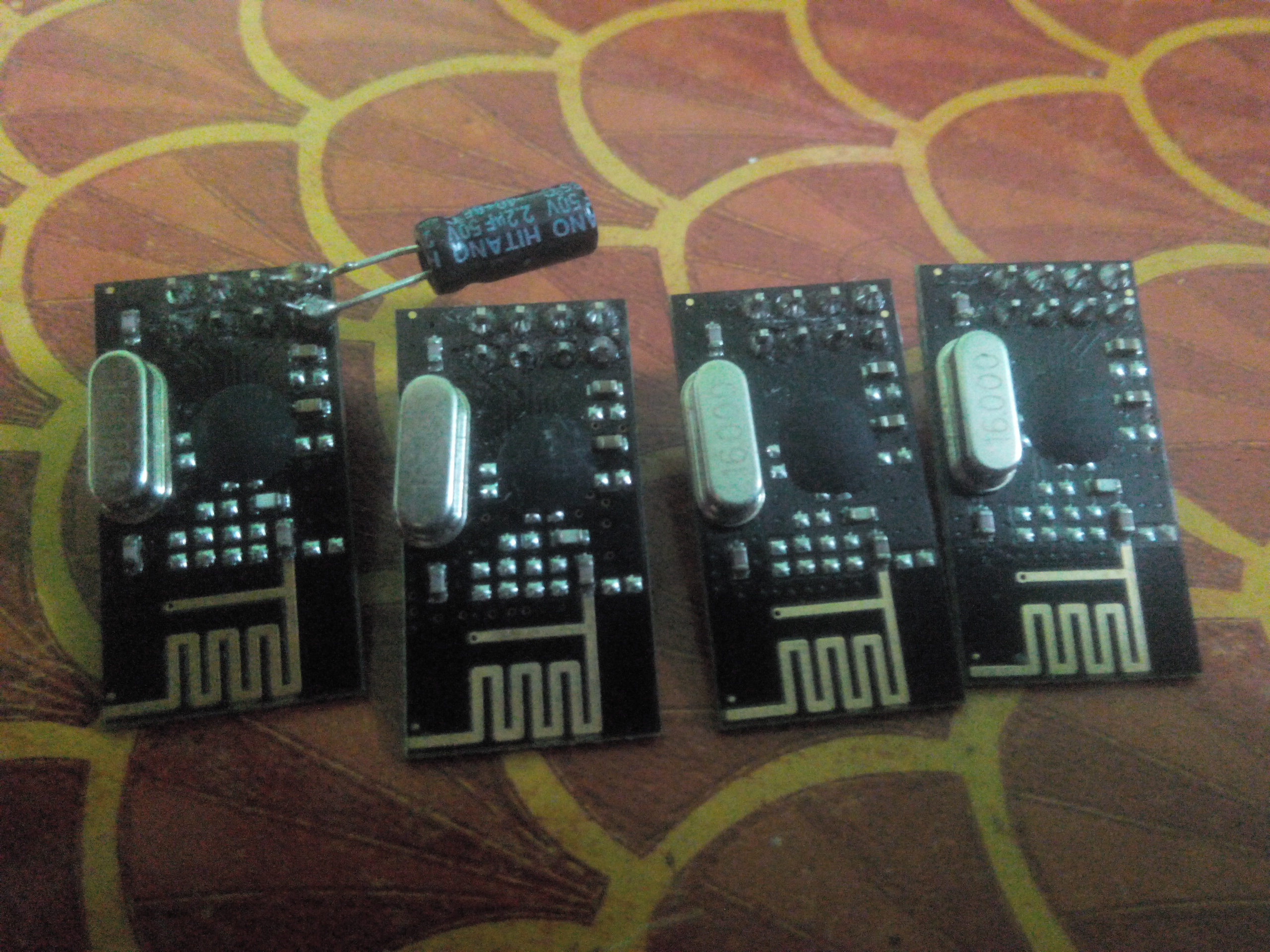
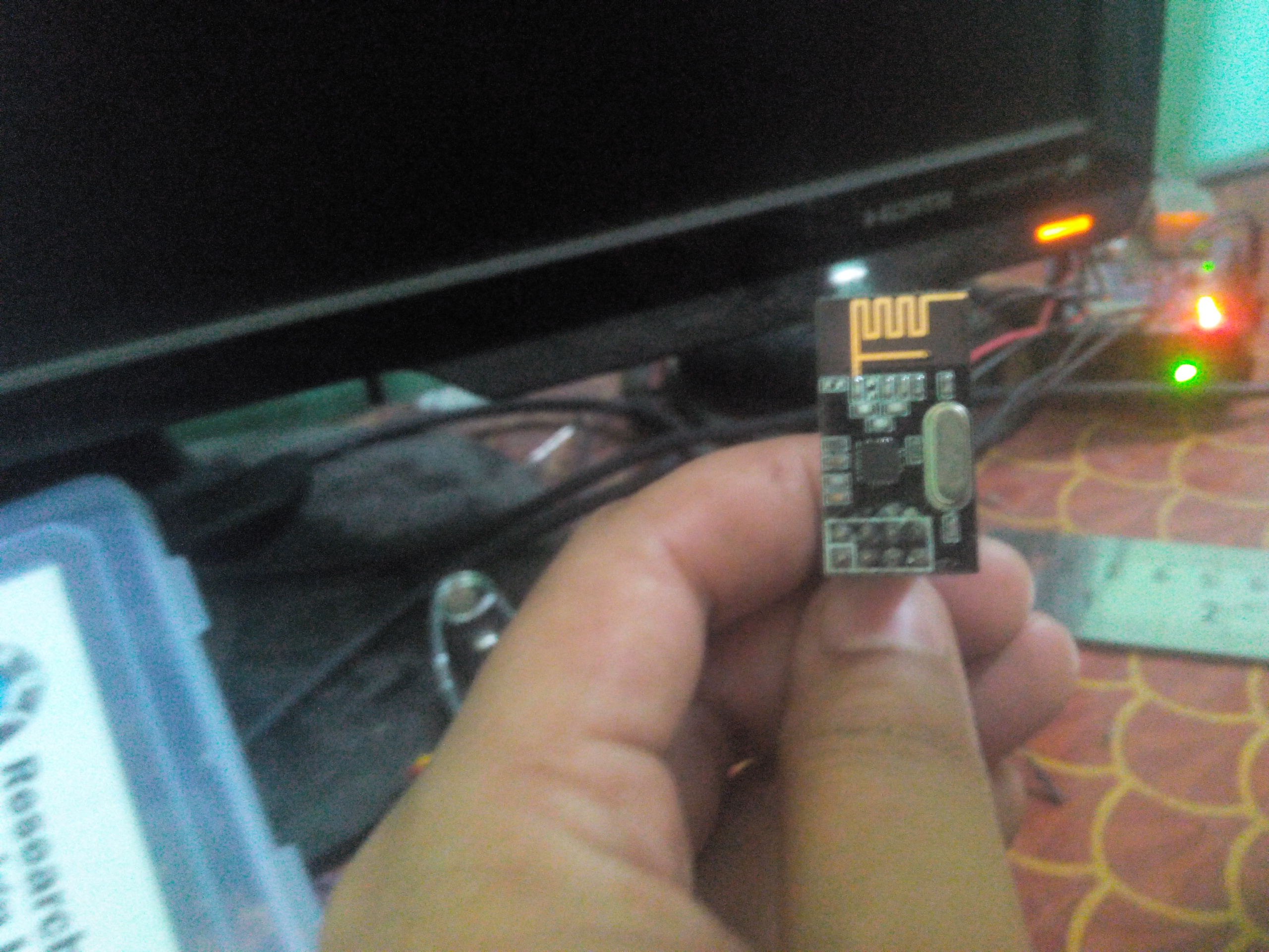
The other one I am using is little better but its not a nrf+, I had to disable the isPvariant(), check to solve the check wires problem.
-
RE: Dimmer sensor
Can the dimmer led actuator example be used to dim a AC 60w incandescent bulb connected 220v connection. If yes what are the modification needed.
when it comes to controlling the speed of a FAN or dimming a normal tungsten filament bulb. I have found so many answers but not a single one which explains all.
-
RE: Arduino 220V AC wattmeter
I have a relay connected to a two way switch, I want to know when the switch was pressed. Basically I want to control the device via both the switch and the app which controls the relay. In case someone switches on the device from physical switch I want to update the app to show that the device is switched on. Hence using the current sensor to sense the current between the switch.
-
RE: Arduino 220V AC wattmeter
@axillent said:
I made one. It is not just wattmeter, it is a 3 channel power switch with meter function per each channel
in general you have just two solution while you want to keep your arduino be isolated from AC line:
- using special chip like ACS712
in both ways you will need analog inputs to measure related voltage and you will be able to calculate current based on analog read
I have tried using ACS712 to check if current is passing through the circuit, from the sketch I am using, sometimes even though the switch is off I get readings, Is there a way to make it full proof so that if there is no current there should not be false reading.
Do you have any sketch related to the implementation?
-
RE: Dimmer sensor
I have kind of implemented the fan control with a new message type V_FAN, but anyways I will check this out and revert after testing
-
RE: Arduino 1.6.0 and MySensors
I upgraded to 1.6.1 and tried writing the gateway code to arduino with the w5100 ethernet shield. The check wires problem still remains the same.
I did as mentioned in some post to disable the soft SPI and then uploaded the sketch and it worked fine. I guess w5100 problem still persists -
RE: Controlling speed of an AC 230v FAN. Help Needed[RESOLVED]
Help needed with adding a new message type. I want to add V_FAN to identify the fan. I am not able to send the message from gateway.
I am trying to check message.type = V_FAN, but nothing is happening, I think this message is never arriving at the node.
-
RE: INA219 DC Current Sensor
I am using a two way switch to control my device. The idea is to control the state from arduino as well as physical switch parallely.
Physical switch ON, Arduino can switch it OFF
Arduino switches it ON, Physical switch whatever be the state on push should switch it OFF.I have used the Relay actuator example code from mysensor and little more code which I found in arduino forum.
I am not able to use the plugin to embed the code, anyways the following is the code.
// Example sketch showing how to control physical relays.
// This example will remember relay state even after power failure.#include <MySensor.h>
#include <SPI.h>#define RELAY_1 2 // Arduino Digital I/O pin number for first relay (second on pin+1 etc)
#define RELAY_2 3
#define NUMBER_OF_RELAYS 2 // Total number of attached relays
#define RELAY_ON 1 // GPIO value to write to turn on attached relay
#define RELAY_OFF 0 // GPIO value to write to turn off attached relay
#define CHILD_ID 1#define CURRENT_SENSOR A0 // Analog input pin that sensor is attached to
MyMessage msg(CHILD_ID, V_TRIPPED); //Using this as the message to report the physical switch on statusfloat amplitude_current; //amplitude current
float effective_value;
bool switch_1_on;
int count = 0;
MySensor gw;void setup()
{
// Initialize library and add callback for incoming messages
gw.begin(incomingMessage, 21, true);// Send the sketch version information to the gateway and Controller
gw.sendSketchInfo("Relay with current sensor", "1.0");
pins_init();// Fetch relay status
for (int sensor=1, pin=RELAY_1; sensor<=NUMBER_OF_RELAYS;sensor++, pin++) {
// Register all sensors to gw (they will be created as child devices)
gw.present(sensor, S_LIGHT);
// Then set relay pins in output mode
pinMode(pin, OUTPUT);
// Set relay to last known state (using eeprom storage)
digitalWrite(pin, gw.loadState(sensor)?RELAY_ON:RELAY_OFF);
}
}void loop()
{
int sensor_max;
sensor_max = getMaxValue();
Serial.print("sensor_max = ");
Serial.println(sensor_max);
//the VCC on the Grove interface of the sensor is 5v
amplitude_current=(float)(sensor_max-512)/10245/1851000000;
effective_value=amplitude_current/1.414;
//minimum_current=1/10245/1851000000/1.414=18.7(mA)
//Only for sinusoidal alternating current
Serial.println("The amplitude of the current is(in mA)");
Serial.println(amplitude_current,1);//Only one number after the decimal point
Serial.println("The effective value of the current is(in mA)");
Serial.println(effective_value,1);if (count == 0 && amplitude_current > 30) { switch_1_on = true; Serial.println("physical switch on"); gw.send(msg.set(switch_1_on?"1":"0")); count = 1 ; } else { count = 0 ; }
// Alway process incoming messages whenever possible
gw.process();
}void incomingMessage(const MyMessage &message) {
// We only expect one type of message from controller. But we better check anyway.
if (message.type == V_FAN) {
Serial.println("Message arrived for FAN");
Serial.println(message.sensor);
for(int i=4 ; i<=7; i++) {
digitalWrite(i,0);
}
}
if (message.type==V_LIGHT) {
// Change relay state
digitalWrite(message.sensor-1+RELAY_1, message.getBool()?RELAY_ON:RELAY_OFF);
// Store state in eeprom
gw.saveState(message.sensor, message.getBool());
// Write some debug info
Serial.print("Incoming change for sensor:");
Serial.print(message.sensor);
Serial.print(", New status: ");
Serial.println(message.getBool());
}
}void pins_init()
{
pinMode(CURRENT_SENSOR, INPUT);
}
/Function: Sample for 1000ms and get the maximum value from the S pin/
int getMaxValue()
{
int sensorValue; //value read from the sensor
int sensorMax = 0;
uint32_t start_time = millis();
while((millis()-start_time) < 1000)//sample for 1000ms
{
sensorValue = analogRead(CURRENT_SENSOR);
if (sensorValue > sensorMax)
{
/record the maximum sensor value/
sensorMax = sensorValue;
}
}
return sensorMax;
} -
RE: Controlling speed of an AC 230v FAN. Help Needed[RESOLVED]
I have a dimmer circuit with me which gives digital output. I just want to know the correct message format for the MQTT message. And how to add a new message type ?. Anyone has done this already ?
-
Controlling speed of an AC 230v FAN. Help Needed[RESOLVED]
Has anyone tried to control the speed of a fan.
I have relay connected to a fan. Relay is triggered using RelayActuator example. How can I now control the speed of the fan which is switched on when relay is triggered.
I tried adding a new sensor type V_FAN and I am sending MyMqtt/node_id/sensor_id/V_FAN but I am not able to receive the message type in the message at the node.
Note : I have manually assigned the sensor Id as relay 2 is assigned sensor id 2 by the relayActuator example code.EDIT: It was my mistake, didn't not update the gateway code after adding a new message type.
-
RE: Dimmer sensor
I have the dimmer circuit with me already. I am looking for the sketch to integrate this with the sensor and send message to the gateway using MQTT for controlling the speed of the fan.
Note: I am using a custom controller build using Ruby on Rails(WIP). and ruby-mqtt to send message to the MQTT gateway which is running mysensor code.
-
RE: INA219 DC Current Sensor
I am using ACS712 current sensor with the relay actuator code to sense if someone has manually switched on the light from the physical switch mounted on the walls. If I can help ping me.
-
RE: Dimmer sensor
Can this dimmer sketch be used to control the speed of a fan ? If yes then what are the changes I need to do to this sketch. As part of a project I am working on, I intend to control a AC 230V fan using arduino. I was planning to create a sketch which explicitly controls a AC FAN.
By doing this am I reinventing the wheel or someone has done this already which I can use. -
RE: MQTT Broker Gateway with ruby-mqtt
MyMQTT/20/1/V_LIGHT.bytes returns me 19, If I add 1 also in the message I get 20. I don't know how it is arriving at number 24.
-
RE: EEPROM values behaving strangely in RelayActuator example
I am testing that example as of now, so added that there. Ideally the EEPROM should be cleared before writing new code to the board to prevent it from reading redundant state which was saved in the microcontroller earlier for some other code. we can move this to the main code so that it is included globally. I added it there so that someone else using that example doesn't get strange values and spend hours trying to decode the library.
-
RE: EEPROM values behaving strangely in RelayActuator example
I Have made the necessary changes in the code and have send a pull request. If that helps the admin can merge else this topic and pull request can be closed
-
EEPROM values behaving strangely in RelayActuator example
My opinion is to clear the EEPROM before calling gw.loadstate(). in the example. while testing if there is a value previously written in some address it gives inconsistent output. Clearing the value in setup should be done before saving any state.
-
RE: MQTT Gateway + wi-fi instead of ethernet
@vladimir Can you put more details, like the gateway will be running on a Rpi or arduino.
If its a Rpi, then I have not tried yet, but for arduino, the overhead of adding a wifi shield and configuring it will be too much.
one way is to use a arduino YUN board which has inbuilt wifi and libraries. Or best go ahead with ethernet.I gave up personally the wifi after trying a lot. If you come out with the solution do share, I would also love to have a look.
-
RE: MQTT Broker Gateway with ruby-mqtt
The following is the code I am using.
-
I am running the mqtt gateway code in an arduino with ethernet shield taken from mysensor library.(Only changes was to enable soft SPI)
-
Using ruby gem mqtt from ruby-mqtt.
-
Then I am creating a client as per the documentation.
client = MQTT::Client.connect('192.168.1.234'). My Gateway is running at the given IP. -
Then following the gateway code example 'broker_prefix/node_id/sensor_id/sensor_type', message
I am sending client.publish('MyMQTT/20/1/V_LIGHT', 1) which is actuating my relay. Everything fine till here
but the issue is I get 24 as the return value when client.publish('MyMQTT/20/1/V_LIGHT', 1) is executed. The same value comes for any sensor_id or node_id.Is 24, which is returned is the default value for acknowledgement ? I was not able to find code which supports my assumption.
-
-
MQTT Broker Gateway with ruby-mqtt
I am trying to write a ruby on rails app for controlling my house. I am using MQTT gateway from mysensor. I am able to send message using the ruby-mqtt (mqtt gem) and actuate a relay.
The issue is I get 24 as return value for any message that I pass to the gateway. What is this '24' return value exactly. Please HELP
-
RE: [SOLVED] Problems with Ethernet Gateway (Arduino Ethernet Shield)
@korttoma Can you post the link to the updated code and the instruction of using NRF with ethernet module.
-
RE: Getting the NRF24L01+ to work on the RPi
I faced similar issue and @TMRh20Projects replied in arduino forum. My issue was beacuse of cheap NRF modules chinese clones. After I replaced with good genuine ones, everything worked like a charm. Please check the NRF modules you are using. I wasted three days to figure out if there was some code issue, when at the end it was the NRF which created all the mess
-
RE: MQTT Client gateway
@ntruchsess said:
<prefix>/<nodeId>/<childId>/<variable_type> is forwarded as a C_SET-msg to the MySensors radio.
Hi, I followed the steps, gateway started but not able to use the existing mysensors sketch. I tried with relay and motion sensor but I get nothing in the serial monitor of MQTT client gateway.
Am I missing something here ?
-
Anyone Using Rpi as MQTT gateway ?
Hi
Is there anyone using MQTT as gateway for connecting to openHab running on another Rpi. If so please help with any links, post or any information to direct me on the right path.
-
RE: MQTT Gateway not reachable when power goes and come.
Using arduino as gateway is more of a overhead. Its creating more problem then solving any.
-
Like you said, I had not tested the router reset scenario and same thing happens for router reset after power outage. The router takes a while to boot up and by this time arduino is already running. So same Destination host unreachable issue.
-
Considering router is running and arduino is powered down for some reason. I have to manually reset the shield so that it can connect to the network.
Is there a better way of solving both the problems ?. Thinking of using Rpi as gateway and Rpi as the server to talk to gateway.
-
-
RE: MQTT Gateway "hangs" when reconnecting
I am facing similar issue, gateway not reachable after a power outage. Have to manually reset the arduino. Please help
-
MQTT Gateway not reachable when power goes and come.
My MQTT gateway becomes not reachable after there a power outage. I have to manually reset it from the button on the board. Is anyone else facing similar issue
-
RE: Mutiple sensors with Interrupt
@BulldogLowell said:
You may very likely do this completely without interrupts......
I am planning to use current sensor with each and every switch around the house to know if someone pressed the switch. Is there a better way of doing this, then the one I am thinking.
Can you please explain, what did you mean by I can achieve this without interrupts.
-
Mutiple sensors with Interrupt
Hi All,
I am planning to connect a 8 channel relay with arduino in a room. I am also going to attach a current sensor to each relay to know if someone has switched on a device manually(To know the state of the switch).
As per my knowledge till now, only pin 2 and 3 of arduino support interrupt. If I have to send a message based on the manual operation of switch, that is current sensor reading the load and sending message to openHAB, how to go ahead with this. Am I missing something, can this be achieved ?
Please help with any pointers on this. -
RE: "Check Wires!!!" - N00B needs some help (please)
@Squint said:
//These are default, but you can change them if you like:
const uint8_t SOFT_SPI_MISO_PIN = 16;
const uint8_t SOFT_SPI_MOSI_PIN = 15;
const uint8_t SOFT_SPI_SCK_PIN = 14;
const uint8_t SPI_MODE = 0;Can you explain which are the corresponding pin for an arduino UNO. An image would help noobs like me who have spend almost a week to make this work.
-
Difference between gateway and controller for beginners
I am just starting with IOT, after going through the wiki of openHAB found this site.
For beginners I have connected two arduino with raspberry pi using NRF2401L modules. Still reading on setting up openHAB on PI.
After going through this site I have a confusion. I understood openHAB is a controller. So, a raspberry pi with openHAB installed will mean that it is a "GATEWAY" ?.I am trying to create a tree with PI on top and arduino as child and grandchild each of which will do some function. In my case where does the gateway comes in picture. Do I need one more arduino connected to PI through nrf2401L or a different type of connection which will act as my "gateway".
Some one with knowledge help me out to understand the use of gateway, why it is needed and how to start with simple one raspberry pi and two arduinos to begin with.