@nca78 well, after 2 nights of intense trying and failing I've got code to work as expected. And yes, it works with PORT interrupt, its kinda more code for you to write in compare to simply using attachInterrupt function, but I'm okay with that. For me double the price of 52832 compared to 51822 is significant. And for now, for a simple sensor stuff as we do with mysensors I don't really see any advantages except that interrupt bug fixed.
Also I've found that Mysensors sleep function for nrf5 is missing one very important command, I don't know why, maybe it is nrf51822 specific and thus @d00616 missed it but in current version of Mysensors library it doesn't disable UART before sleep, that's why I was getting 120-200uA current during sleep. I still don't really know how to make pull requests on github, so I guess I will just post it here:
line 290 of MyHwNRF5.cpp should contain: NRF_UART0->ENABLE=0; and line 327: NRF_UART0->ENABLE=1; respectively. That completely disables UART on nrf51822.
I will post my complete sketch later, when I will finish it, maybe someone who strugles as I did will find it useful. Also I think we need to somehow combine all examples that were posted in this thread or at least put a list of them with links, because looking through 1654 posts is not an easy task, especially if you not sure what you are looking for exactly.
monte
Posts
-
nRF5 action! -
What did you build today (Pictures) ?Made a prototype board for writing a software for one of my projects. Goal was to have everything needed on a board no bigger then a 1.54" eink display, and to make it doable at home by my own.
I was gladly surprised that everything worked (after a sleepless night of fighting through-layer connections, and soldering/desoldering FPC connectors) :) The only I've messed up is order of connector pins, so the display is connected the wrong way...
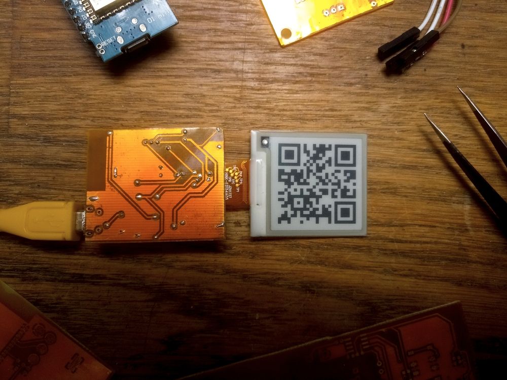
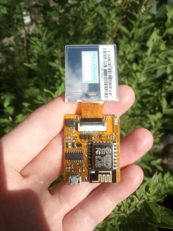
It also has pads for SHT30 sensor so it may be somehow useful after development is done.
-
Where did everyone go?I guess the main reason is that mysensors is very stand-alone framework. And it locked itself in purely hobbyist territory. So when there are vast amount of iot devices from various manufacturers that you can combine with your own diy solutions in zigbee-ikea-hue or esp-tasmota-mqtt ecosystem in mysesnsors you have to make all devices yourself if you want some kind of ecosystem, or rely on HA/openhab/nodered/domoticz with its script system to make something connected. Also strict requirement of arduino framework and outdated hardware as the core of the framework alienates the big chunk of iot developers out there. It feels like people come to mysensors, make relay node, temperature sensor and then go forward for more complex solutions to never come back.
@NeverDie said in Where did everyone go?:
not all that long ago Google bought a thermostat company (Nest)
And pretty much broke it for opensource or third-party integrations.
-
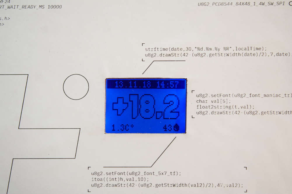
What did you build today (Pictures) ?Build myself a simple temperature sensor with a clock. No RTC, just pulling time from controller and updating every 10 minutes to avoid drift. Also requesting outdoor temperature from controller. Build from what was lying around - DHT22, pro mini clone, nokia screen. I can share the code if someone needs it :)

-
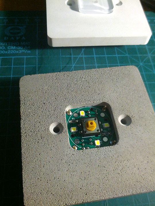
What did you build today (Pictures) ?Offtopic in terms of mysensors platform, but somehow tangent to a home automation. I've made a batch of concrete switches/push buttons which are in this case simple buttons with led backlight and all the logic is located centrally in distribution box, based on KNX ABB module. But I am planning on making smarter and more complex version which could use Mysensors as its transport.

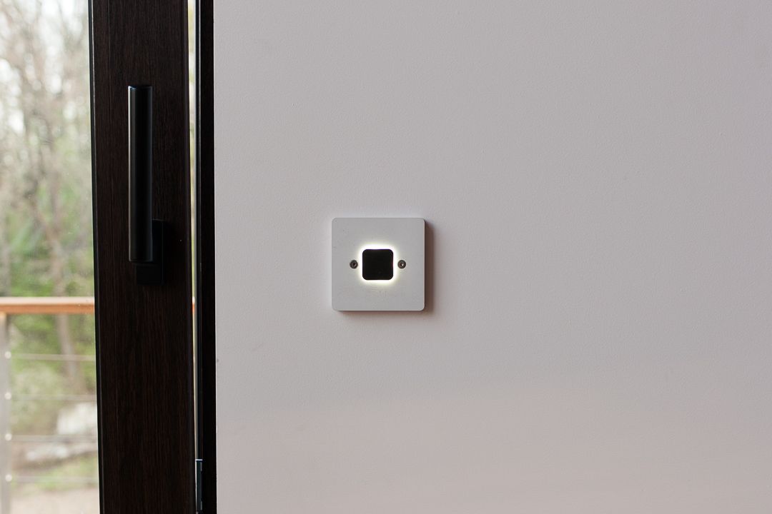
and a photo of insides of one of the prototypes at first stages of development
-
What did you build today (Pictures) ?Today I've finally swapped my outdoor relay node with something descent.
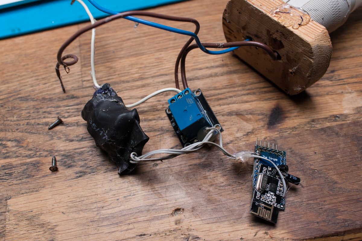
This was my very first mysensors node that I've built when I was only starting to mess with arduino, probably around four years ago.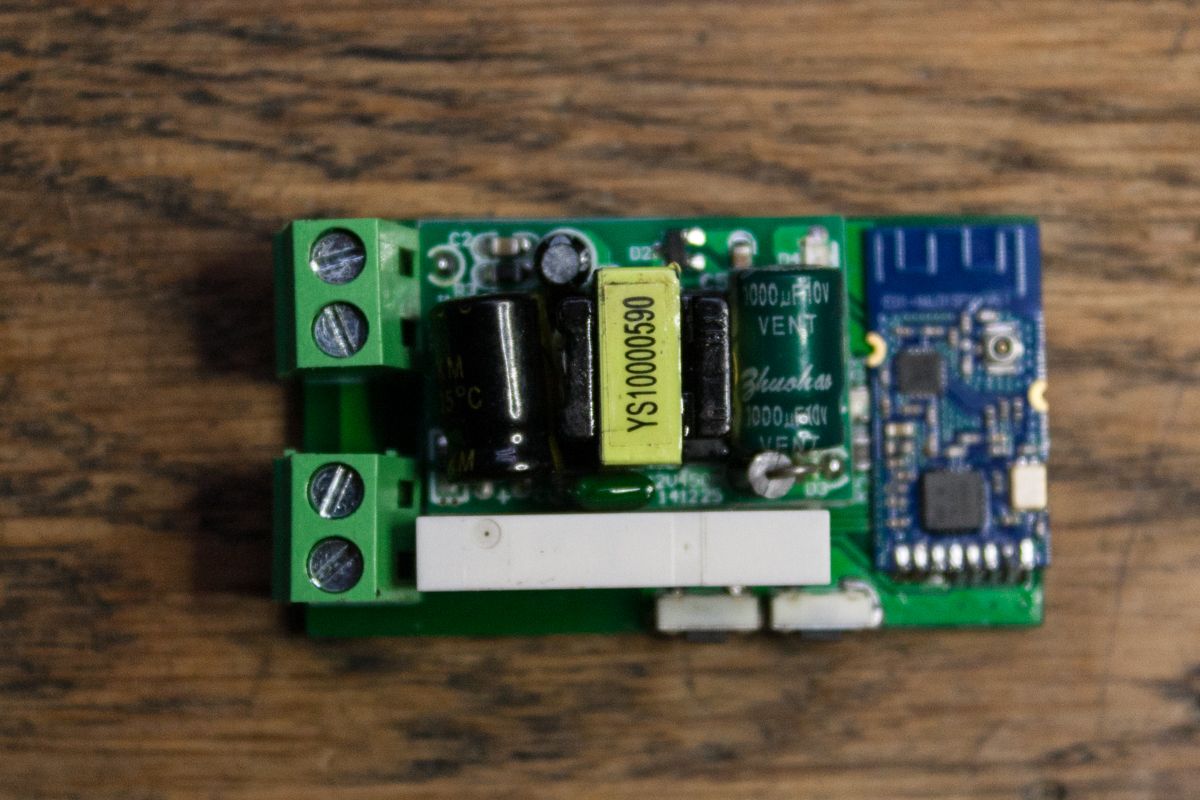
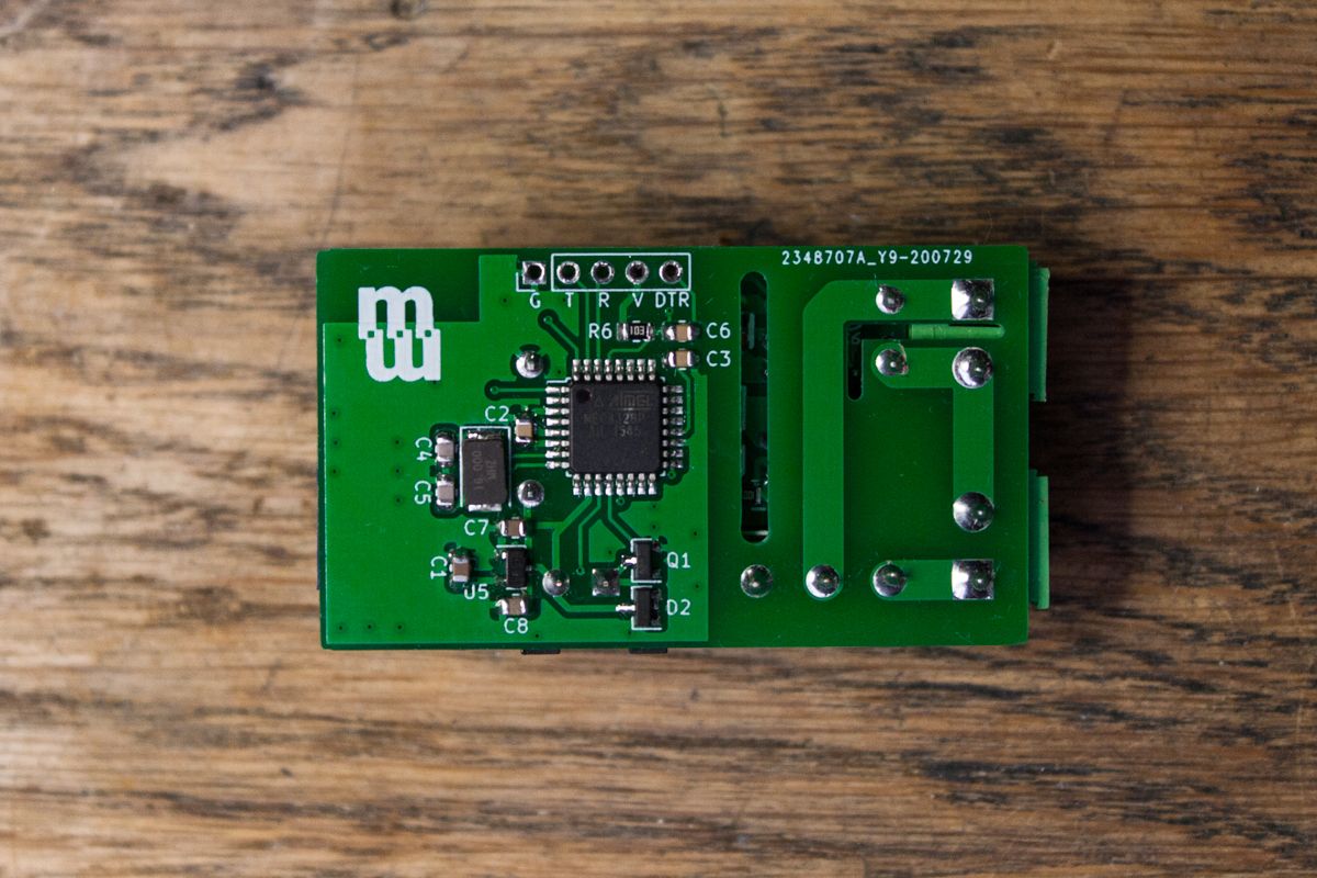
This board uses cheap 5v power supply and an amplified version of NRF24 module from Ebyte. It supposed to be poured with silicone ore resin, but I am yet to find suitable box, the size of this board appeared to be bigger then most of such cases designed for compound pouring. But I'm planning on making next version, with non-isolated power supply, which will help to achieve smaller size. -
What did you build today (Pictures) ?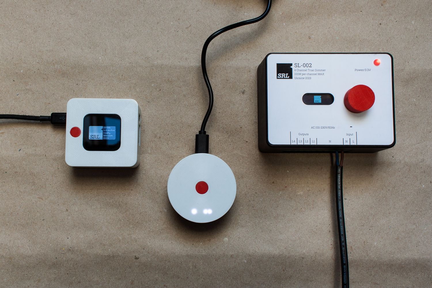
From left to right:- Home Assistant server with built-in NRF24 radio and OLED display based on Orange Pi Zero
- MQTT Mysensors gateway with ESP8285
- 4 channel triac dimmer with oled display and UI for operating in standalone mode.
-
Direct pairing of two nodes implementationI've been looking for some time for implementation of pairing two nodes to each other to be able to send messages directly omitting controller. I've seen some other posts suggesting to add this functionality to mysensors core, and proposing base scheme of how it should look like. After some reading I realized that it is not hard to write such code by myself. So I tried my best and now I have what seems to be a working code for two test nodes and a gateway. One of the nodes is modified sketch for binary button the other one is simple one channel relay. I'm not a professional programmer, so code can be optimized more, I guess, and maybe rewritten in better manner.
It's primarily useful for direct communication between a button node (a light switch, or motion sensor) and some relay or other actuator. The key feature is the ability to avoid necessity of controller presence for some simple usage like light switching. Also it provides better reliability in case of controller failure.
Both nodes must have specific pairing button which also serves as "Clear EEPROM" button if pressed before node is powered on. So basically when pairing button is pressed node enters pairing mode for required amount of time (in my case 10 seconds) and sends special message to controller which collects its node and children id's and then waits for 10 seconds for another node to send request in which case it then sends id's vice versa. My code is written only for single button/relay nodes, but it can be made to pair specific child sensors on every node.
Let me know what do you think of it, and if it's useful to anybody.
Binary button code:
// Enable debug prints to serial monitor
#define MY_DEBUG

// Enable and select radio type attached
#define MY_RADIO_NRF24

#include <MySensors.h>

#define CHILD_ID 3

#define SET_BUTTON_PIN 5// Arduino Digital I/O pin for button/reed switch
#define BUTTON_PIN 3

MyMessage msg(CHILD_ID, V_TRIPPED);
bool firstLoop = 1;
bool pairing = 0;
int node_pair=-1;
int sensor_pair=-1;
bool paired=0;
bool lastButState=0;
unsigned long timer1 = 0;
int debounceTime = 1000;
unsigned long timer2 = 0;
int pairWaitTime = 10000;
unsigned long timer3;
int holdTime = 3000;

//Time counter function instead of delay
boolean isTime(unsigned long *timeMark, unsigned long timeInterval) {
    if (millis() - *timeMark >= timeInterval) {
        *timeMark = millis();
        return true;
    }
    return false;
}

void before()
{
  Serial.begin(115200);
  Serial.println("Starting node...");
  pinMode(SET_BUTTON_PIN, INPUT_PULLUP); //Eneble button pin for detect  request for resetting node's EEPROM
  bool clr = digitalRead(SET_BUTTON_PIN);
  if (!clr) {
    Serial.println("Clearing EEPROM");
    for (int i=0; i<EEPROM_LOCAL_CONFIG_ADDRESS; i++) {
    hwWriteConfig(i,0xFF);
    }
    //Clearing paired nodes address and paired state
    for (int i=245; i<=255; i++) {
    hwWriteConfig(i,0xFF);
    }
    Serial.println("EEPROM is clean");
  }
  //Reading pairing state from EEPROM and then reading paired nodes id's if paired
  paired = loadState(255);
  Serial.print("Paired state: ");
  Serial.println(paired);
    if (paired) {
    node_pair = loadState(245);
    sensor_pair = loadState(246);
    Serial.print("Paired node: ");
    Serial.print(node_pair);
    Serial.print("-");
    Serial.println(sensor_pair);
  }
}

void setup()
{
	// Setup the buttons
	pinMode(BUTTON_PIN, INPUT_PULLUP);
}

void presentation()
{
	// Send the sketch version information to the Controller in case node is'nt paired
	if (!paired) {
    sendSketchInfo("Binary paired button", "1.0");
    present(CHILD_ID, S_MOTION);
	}

}

// Loop will iterate on changes on the BUTTON_PINs
void loop()
{
  bool butState = !digitalRead(BUTTON_PIN);
  if (!paired) {
    if (firstLoop) {
      timer3 = millis(); //Starting delay for pairing button on first loop
    }
    //If pairing button hold for required amount of seconds initiate pairing process
    if (!digitalRead(SET_BUTTON_PIN)) {
      if(isTime(&timer3, holdTime)){
        Serial.println("Pair button pressed");
        pair();
        if (!paired) {
          Serial.println("Pairing timeout");
        }
      }
    } else {
      timer3 = millis();
    }
  }
  //Processing main button press
  if (butState != lastButState) {
    if (butState) {
      lastButState = butState;
      if (isTime(&timer1, debounceTime)) {
        Serial.println("Button pressed");
        //If node is paired to other node send message directly to paired node omitting controller
        if (paired) {
         MyMessage msg(sensor_pair, V_TRIPPED);
         msg.setDestination(node_pair);
         Serial.println("Sent message to paired node");
         int retry = 0;
         while(!send(msg.set(1)) || retry == 10) {
          wait(100);
          send(msg.set(1));
          retry++;
         }
        } else {
          //If not, send message to controller
         send(msg.set(1));
         Serial.println("Sent message to controller");
        }
      }

    } else {
      if (!paired) {
        send(msg.set(0));
      }
      lastButState = butState;
    }
  }
	firstLoop = 0; //Counter for first loop just to know from where to start timer for pairing button hold
}

//Pairing function
void pair()
{
  Serial.println("Entering pairing mode");
  pairing = 1;
  MyMessage pairMsg(244, V_VAR1); //I'm using specific CHILD_ID to be able to filter out pairing requests
  send(pairMsg.set("Pair me."), true); //Send any message to gateway
  Serial.println("Pair request sent");
  //Then we wait some time to recieve paired node id (in my case 10 seconds)
  timer2 = millis();
  while (!isTime(&timer2, pairWaitTime)) {
    wait(1);
    if (paired) {
      Serial.println("Successfully paired");
      break;
    }
  }
  pairing = 0;
}

void receive(const MyMessage &message)
{
  //While in pairing mode we'll only process pairing messages
  if (pairing) {
    if (!message.sender) {
      if (message.type == V_VAR2) {
        node_pair = atoi(strtok(message.getString(), ";")); //Deconstructing string from gateway, wich must contain id of paired node
        Serial.println(node_pair);
        sensor_pair = atoi(strtok(NULL, ";")); //...and id of specific sensor on that node, in case there are more than one
        Serial.print("Paired with: ");
        Serial.println(node_pair);
        Serial.println(sensor_pair);
        paired=1;
        saveState(255, 1);
      }
    }
  }
}
Relay actuator code:
// Enable debug prints to serial monitor
#define MY_DEBUG

// Enable and select radio type attached
#define MY_RADIO_NRF24
//#define MY_RADIO_RFM69

// Enable repeater functionality for this node
//#define MY_REPEATER_FEATURE

#include <MySensors.h>


#define CHILD_ID 1
#define RELAY_PIN  5  // Arduino Digital I/O pin number for relay
#define RELAY_ON 1  // GPIO value to write to turn on attached relay
#define RELAY_OFF 0 // GPIO value to write to turn off attached relay
#define SET_BUTTON_PIN 3

bool relayState;
bool firstLoop = 1;
bool pairing = 0;
int node_pair=-1;
int sensor_pair=-1;
bool paired=0;
bool lastButState=0;
unsigned long timer1 = 0;
int debounceTime = 100;
unsigned long timer2 = 0;
int pairWaitTime = 10000;
unsigned long timer3;
int holdTime = 3000;
unsigned long timer4;
int resendTime = 1500;

MyMessage msg(CHILD_ID,V_LIGHT);


//Time counter function instead delay
boolean isTime(unsigned long *timeMark, unsigned long timeInterval) {
    if (millis() - *timeMark >= timeInterval) {
        *timeMark = millis();
        return true;
    }
    return false;
}

void before ()
{
  Serial.begin(115200);
  Serial.println("Starting...");
  pinMode(SET_BUTTON_PIN, INPUT_PULLUP);
  bool clr = digitalRead(SET_BUTTON_PIN);
  if (!clr) {
    Serial.println("Clearing EEPROM");
    for (int i=0; i<EEPROM_LOCAL_CONFIG_ADDRESS; i++) {
    hwWriteConfig(i,0xFF);
    }
    //Clearing paired nodes address and paired state
    for (int i=245; i<=255; i++) {
    hwWriteConfig(i,0xFF);
    }
    Serial.println("EEPROM is clean");
  }
  //Reading pairing state from EEPROM and then reading paired nodes id's if paired
  paired = loadState(255);
  Serial.print("Paired state: ");
  Serial.println(paired);
  if (paired) {
    node_pair = loadState(245);
    sensor_pair = loadState(246);
    Serial.print("Paired node: ");
    Serial.print(node_pair);
    Serial.print("-");
    Serial.println(sensor_pair);
  }
  pinMode(RELAY_PIN, OUTPUT);
  digitalWrite(RELAY_PIN, 1);
  delay(1000);
  digitalWrite(RELAY_PIN, 0);
  // Set relay to last known state (using eeprom storage)
  relayState = loadState(CHILD_ID);
  digitalWrite(RELAY_PIN, relayState ? RELAY_ON : RELAY_OFF);
}
void setup()
{

}

void presentation()
{
  // Send the sketch version information to the gateway and Controller
  sendSketchInfo("Relay", "1.0");

  present(CHILD_ID, S_LIGHT, "Test light", true);

  // Send saved state to gateway (using eeprom storage)
  send(msg.set(relayState),true);
}

void loop()
{
  if (!paired) {
    if (firstLoop) {
      timer3 = millis(); //Starting delay for pairing button on first loop
    }
    //If pairing button hold for required amount of seconds initiate pairing process
    if (!digitalRead(SET_BUTTON_PIN)) {
      if(isTime(&timer3, holdTime)){
        Serial.println("Pair button pressed");
        pair();
      }
    } else {
      timer3 = millis();
    }
  }
  firstLoop = 0; //Counter for first loop just to know from where to start timer for pairing button hold
}

void pair()
{
Serial.println("Entering pairing mode");
  pairing = 1;
  MyMessage pairMsg(244, V_VAR1); //I'm using specific CHILD_ID to be able to filter out pairing requests
  send(pairMsg.set("Pair me."), true); //Send any message to gateway
  Serial.println("Pair request sent");
  //Then we wait some time to recieve paired node id (in my case 10 seconds)
  timer2 = millis();
  while (!isTime(&timer2, pairWaitTime)) {
    wait(1);
    if (paired) {
      Serial.println("Successfully paired");
      break;
    }
  }
  pairing = 0;
  Serial.println("Pairing timeout");
}

void receive(const MyMessage &message) {
  //While in pairing mode we'll only process pairing messages
  if (pairing) {
    if (!message.sender) {
      if (message.type == V_VAR2) {
        node_pair = atoi(strtok(message.getString(), ";")); //Deconstructing string from gateway, wich must contain id of paired node
        Serial.println(node_pair);
        sensor_pair = atoi(strtok(NULL, ";")); //...and id of specific sensor on that node, in case there are more than one
        Serial.print("Paired with: ");
        Serial.println(node_pair);
        Serial.println(sensor_pair);
        paired=1;
        saveState(255, 1);
      }
    }
  } else { //Process mesage from gateway
    if (message.type == V_LIGHT && !message.sender) {
      // Change relay state
      relayState = message.getBool();
      digitalWrite(RELAY_PIN, relayState ? RELAY_ON : RELAY_OFF);
      // Store state in eeprom
      saveState(CHILD_ID, relayState);
      // Write some debug info
      Serial.print("Incoming change. New status:");
      Serial.println(relayState);
    } else if (message.type == V_TRIPPED && message.sender == node_pair) { //Process message sent directly from paired node
      if(isTime(&timer4, resendTime)) {
        digitalWrite(RELAY_PIN, relayState ? RELAY_OFF : RELAY_ON);
        relayState = relayState ? 0 : 1;
        saveState(CHILD_ID, relayState);
        send(msg.set(relayState)); //Send changed state to controller, because paired button won't do it
      }
    }
  }
}
Gateway code:
// Enable debug prints to serial monitor #define MY_DEBUG // Enable and select radio type attached #define MY_RADIO_NRF24 //#define MY_RADIO_RFM69 // Set LOW transmit power level as default, if you have an amplified NRF-module and // power your radio separately with a good regulator you can turn up PA level. #define MY_RF24_PA_LEVEL RF24_PA_MAX // Enable serial gateway #define MY_GATEWAY_SERIAL // Define a lower baud rate for Arduino's running on 8 MHz (Arduino Pro Mini 3.3V & SenseBender) #if F_CPU == 8000000L #define MY_BAUD_RATE 38400 #endif // Set blinking period #define MY_DEFAULT_LED_BLINK_PERIOD 300 #include <MySensors.h> unsigned long currentTime = 0; int waitTime = 10000; int node1_addr = 0; bool node1_addr_present = 0; int sensor1_addr = 0; char str1[8]; char str2[8]; bool pairing = 0; //Messages for answering pairing requests MyMessage msg(254,V_VAR2); MyMessage msg2(254,V_VAR2); //Time counter function instead delay boolean isTime(unsigned long *timeMark, unsigned long timeInterval) { if (millis() - *timeMark >= timeInterval) { *timeMark = millis(); return true; } return false; } void setup() { // Setup locally attached sensors } void loop() { //We are keeping ids of pairing nodes only for 10 seconds while pairing if(isTime(¤tTime, waitTime)) { node1_addr = 0; node1_addr_present = 0; } } void receive(const MyMessage &message) { //I used specific message type for filtering out pairing request if (message.type == V_VAR1) { Serial.print("Incoming message. Node - "); Serial.print(message.sender); Serial.print(message.sensor); Serial.println(message.getString()); //Check if there was any pairing requests for last 10 seconds, if no begin pairing process if (!node1_addr_present) { currentTime = millis(); node1_addr = message.sender; sensor1_addr = message.sensor; node1_addr_present = 1; } //If there is request from another node send back pairing node ids to each other else if (message.sender != node1_addr && message.sensor != sensor1_addr) { snprintf(str2, 7, "%d;%d", message.sender, message.sensor); //Construct message string with node and sensor ids of second node snprintf(str1, 7, "%d;%d", node1_addr, sensor1_addr); //...and the first one //print some debug info Serial.print("First address: "); Serial.print(str1); Serial.print("Second address: "); Serial.print(str2); //Send answer to nodes msg.setDestination(message.sender); send(msg.set(str1), true); wait(500); Serial.println("Sent message to second address"); msg2.setDestination(node1_addr); send(msg2.set(str2), true); wait(500); Serial.println("Sent message to first address"); node1_addr = 0; sensor1_addr = 0; node1_addr_present = 0; Serial.println("Pairing finished"); } } } -
Favorite hand solderable radio chip?@NeverDie stencil would help, for sure. But I am talking bare minimum. You tin the pads a little, so they are like bumps, then apply gel flux, put the IC aligned to the pins and reflow it with hot-air gun. That may be not the best practice, but it works, if you need to solder few IC's.
-
nRF5 action!I wanted to write that Softdevice and ESB are not compatible for use at the same time, but then decided to fact check myself. Seems like now you can use Softdevice and ESB simultaneously. You can either disable softdevice in program, or use Timeslot API to manage access to radio of different protocols.
https://infocenter.nordicsemi.com/index.jsp?topic=%2Fsds_s140%2FSDS%2Fs1xx%2Fconcurrent_multiprotocol_tsl_api%2Ftsl_usage_examples.html&cp=4_5_3_0_8_2
https://devzone.nordicsemi.com/f/nordic-q-a/55847/priority-level-overlap-between-softdevice-and-esb
https://jimmywongiot.com/2020/06/22/radio-timeslot-api-for-the-multiple-protocols/
If this is doable I can't think of a reason, why mysensors shouldn't use softdevice. -
What did you build today (Pictures) ?@sundberg84 I've bought these 5032 crystals: https://www.aliexpress.com/item/Free-shipping-20pcs-16-000MHZ-16mhz-20pF-2Pin-5032-smd-quartz-resonator-Crystal/32821974003.html but there are plentiful other offers on aliexspress and/or ebay. This 5032 package seems to be the most common. There is another package with the same size but with 4 pins 2 of which are not connected, I bought them from my local distributor, while was waiting a package from aliexpress. But those with 4 pins are harder to solder (obviously) and I don't see any pros of using them.
The most suitable for hand soldering and easiest to find are these: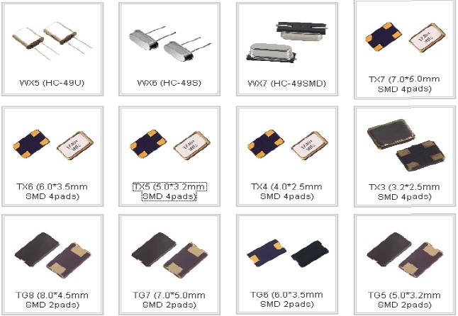
According to this image the ones I have are TX5 and TG5. -
ESP8266 MQTT gateway SSL connectionThere are couple old topics on this forum about secure connection to external MQTT broker, but neither of solutions described there aren't working now. Not so long ago the pull request was added on PubSubClient github which provides SSL connection code available only for esp8266: https://github.com/knolleary/pubsubclient/pull/251. It isn't merged yet, but you can manually install proposed patch from here https://github.com/knolleary/pubsubclient/pull/251/commits/bc9995ba2f7d0a42959685bdae51a014e03514bd.
Another thing you have to do is to modify MyGatewayTransportMQTTClient.cpp in /core folder of your MySensors library. I hope soon someone will make changes to source code, so it won't be necessary.I'm not experienced programmer, so i guess there has to be a better way to add changes to this code, but this way it works at least :
/*
* The MySensors Arduino library handles the wireless radio link and protocol
* between your home built sensors/actuators and HA controller of choice.
* The sensors forms a self healing radio network with optional repeaters. Each
* repeater and gateway builds a routing tables in EEPROM which keeps track of the
* network topology allowing messages to be routed to nodes.
*
* Created by Henrik Ekblad <henrik.ekblad@mysensors.org>
* Copyright (C) 2013-2016 Sensnology AB
* Full contributor list: https://github.com/mysensors/Arduino/graphs/contributors
*
* Documentation: http://www.mysensors.org
* Support Forum: http://forum.mysensors.org
*
* This program is free software; you can redistribute it and/or
* modify it under the terms of the GNU General Public License
* version 2 as published by the Free Software Foundation.
*/


// Topic structure: MY_MQTT_PUBLISH_TOPIC_PREFIX/NODE-ID/SENSOR-ID/CMD-TYPE/ACK-FLAG/SUB-TYPE

#include "MyGatewayTransport.h"

#if defined MY_CONTROLLER_IP_ADDRESS
IPAddress _brokerIp(MY_CONTROLLER_IP_ADDRESS);
#endif

#if defined(MY_GATEWAY_ESP8266)
#define EthernetClient WiFiClient
#if defined(MY_IP_ADDRESS)
IPAddress _gatewayIp(MY_IP_GATEWAY_ADDRESS);
IPAddress _subnetIp(MY_IP_SUBNET_ADDRESS);
#endif
#elif defined(MY_GATEWAY_LINUX)
// Nothing to do here
#elif defined(MY_GATEWAY_ESP8266_SECURE)
#define EthernetClient WiFiClientSecure
#else
uint8_t _MQTT_clientMAC[] = { MY_MAC_ADDRESS };
#endif

#if defined(MY_IP_ADDRESS)
IPAddress _MQTT_clientIp(MY_IP_ADDRESS);
#endif

#if defined(MY_SSL_FINGERPRINT)
const char* fingerprint = MY_SSL_FINGERPRINT;
#endif

static EthernetClient _MQTT_ethClient;

#if defined(MY_GATEWAY_ESP8266_SECURE)
static PubSubClient _MQTT_client(_MQTT_ethClient, fingerprint);
#else
static PubSubClient _MQTT_client(_MQTT_ethClient);
#endif

static bool _MQTT_connecting = true;
static bool _MQTT_available = false;
static MyMessage _MQTT_msg;

bool gatewayTransportSend(MyMessage &message)
{
	if (!_MQTT_client.connected()) {
		return false;
	}
	setIndication(INDICATION_GW_TX);
	char *topic = protocolFormatMQTTTopic(MY_MQTT_PUBLISH_TOPIC_PREFIX, message);
	debug(PSTR("Sending message on topic: %s\n"), topic);
	return _MQTT_client.publish(topic, message.getString(_convBuffer));
}

void incomingMQTT(char* topic, uint8_t* payload, unsigned int length)
{
	debug(PSTR("Message arrived on topic: %s\n"), topic);
	_MQTT_available = protocolMQTTParse(_MQTT_msg, topic, payload, length);
}

bool reconnectMQTT(void)
{
	debug(PSTR("Attempting MQTT connection...\n"));
	// Attempt to connect
	if (_MQTT_client.connect(MY_MQTT_CLIENT_ID
#if defined(MY_MQTT_USER) && defined(MY_MQTT_PASSWORD)
	                         , MY_MQTT_USER, MY_MQTT_PASSWORD
#endif
	                        )) {
		debug(PSTR("MQTT connected\n"));

		// Send presentation of locally attached sensors (and node if applicable)
		presentNode();

		// Once connected, publish an announcement...
		//_MQTT_client.publish("outTopic","hello world");
		// ... and resubscribe
		_MQTT_client.subscribe(MY_MQTT_SUBSCRIBE_TOPIC_PREFIX "/+/+/+/+/+");
		return true;
	}
	return false;
}

bool gatewayTransportConnect(void)
{
#if defined(MY_GATEWAY_ESP8266)
	while (WiFi.status() != WL_CONNECTED) {
		wait(500);
		MY_SERIALDEVICE.print(F("."));
	}
	MY_SERIALDEVICE.print(F("IP: "));
	MY_SERIALDEVICE.println(WiFi.localIP());
#elif defined(MY_GATEWAY_ESP8266_SECURE)
	while (WiFi.status() != WL_CONNECTED) {
		wait(500);
		MY_SERIALDEVICE.print(F("."));
	}
	MY_SERIALDEVICE.print(F("IP: "));
	MY_SERIALDEVICE.println(WiFi.localIP());
#elif defined(MY_GATEWAY_LINUX)
#if defined(MY_IP_ADDRESS)
	//TODO
#endif
#else
#ifdef MY_IP_ADDRESS
	Ethernet.begin(_MQTT_clientMAC, _MQTT_clientIp);
#else
	// Get IP address from DHCP
	if (!Ethernet.begin(_MQTT_clientMAC)) {
		MY_SERIALDEVICE.print(F("DHCP FAILURE..."));
		_MQTT_connecting = false;
		return false;
	}
#endif
	MY_SERIALDEVICE.print(F("IP: "));
	MY_SERIALDEVICE.println(Ethernet.localIP());
	// give the Ethernet interface a second to initialize
	delay(1000);
#endif
	return true;
}

bool gatewayTransportInit(void)
{
	_MQTT_connecting = true;
#if defined(MY_CONTROLLER_IP_ADDRESS)
	_MQTT_client.setServer(_brokerIp, MY_PORT);
#else
	_MQTT_client.setServer(MY_CONTROLLER_URL_ADDRESS, MY_PORT);
#endif

	_MQTT_client.setCallback(incomingMQTT);

#if defined(MY_GATEWAY_ESP8266)
	// Turn off access point
	WiFi.mode(WIFI_STA);
#if defined(MY_ESP8266_HOSTNAME)
	WiFi.hostname(MY_ESP8266_HOSTNAME);
#endif
	(void)WiFi.begin(MY_ESP8266_SSID, MY_ESP8266_PASSWORD);
#ifdef MY_IP_ADDRESS
	WiFi.config(_MQTT_clientIp, _gatewayIp, _subnetIp);
#endif
#endif

	gatewayTransportConnect();

	_MQTT_connecting = false;
	return true;
}

bool gatewayTransportAvailable(void)
{
	if (_MQTT_connecting) {
		return false;
	}
	//keep lease on dhcp address
	//Ethernet.maintain();
	if (!_MQTT_client.connected()) {
		//reinitialise client
		if (gatewayTransportConnect()) {
			reconnectMQTT();
		}
		return false;
	}
	_MQTT_client.loop();
	return _MQTT_available;
}

MyMessage & gatewayTransportReceive(void)
{
	// Return the last parsed message
	_MQTT_available = false;
	return _MQTT_msg;
}
So i added definition of MY_GATEWAY_ESP8266_SECURE option because we need to use WiFiClientSecure method for connection for SSL to work. Also we'll need SSL fingerprint of your MQTT broker, so you'll need to define this option in the code of your gateway. Else changes are duplicating code for MY_GATEWAY_ESP8266 to accommodate new option.
// Enable debug prints to serial monitor
#define MY_DEBUG

// Use a bit lower baudrate for serial prints on ESP8266 than default in MyConfig.h
#define MY_BAUD_RATE 9600

// Enables and select radio type (if attached)
#define MY_RADIO_NRF24

#define MY_GATEWAY_MQTT_CLIENT
#define MY_GATEWAY_ESP8266_SECURE

// Set this node's subscribe and publish topic prefix
#define MY_MQTT_PUBLISH_TOPIC_PREFIX "mygateway1-out"
#define MY_MQTT_SUBSCRIBE_TOPIC_PREFIX "mygateway1-in"

// Set MQTT client id
#define MY_MQTT_CLIENT_ID "mysensors-1"

// Enable these if your MQTT broker requires usenrame/password
#define MY_MQTT_USER "user"
#define MY_MQTT_PASSWORD "password"

// Set WIFI SSID and password
#define MY_ESP8266_SSID "ssid"
#define MY_ESP8266_PASSWORD "Wi-Fi password"

// Set the hostname for the WiFi Client. This is the hostname
// it will pass to the DHCP server if not static.
// #define MY_ESP8266_HOSTNAME "mqtt-sensor-gateway"

// Enable MY_IP_ADDRESS here if you want a static ip address (no DHCP)
//#define MY_IP_ADDRESS 192,168,2,197

// If using static ip you need to define Gateway and Subnet address as well
//#define MY_IP_GATEWAY_ADDRESS 192,168,2,1
//#define MY_IP_SUBNET_ADDRESS 255,255,255,0


// MQTT broker ip address.
#define MY_CONTROLLER_URL_ADDRESS "URL of your MQTT broker"

// The MQTT broker port to to open
#define MY_PORT SSL-port

#define MY_SSL_FINGERPRINT "ssl fingerprint of your MQTT broker"

#include <ESP8266WiFi.h>
#include <MySensors.h>

void setup()
{
}

void presentation()
{
	// Present locally attached sensors here
}


void loop()
{
	// Send locally attech sensors data here
}
Let me know what do you think about it.
-
Where did everyone go?@NeverDie I am just paranoid about relying on a cloud for everything. What if, lets say, my internet connection is cut off, or theirs or they decide to close the API (like google did to nest). I don't like my data taking such a long detour. That's why I installed nextcloud at home when dropbox decided they didn't need to support anything except ext4 on linux :)
-
Best PC platform for running Esxi/Docker at home?+1 for proxmox. Didn't have good experience with esxi. Proxmox is opensource, free and debian-based. Using it on HP microserver gen 8.
As for CPU choice I don't see how there would be any issue with Ryzen. All you need from processor is hardware virtualization, and I think all except the lowest level ones have it nowadays. -
Control temperature of double white LED stripesNow you can buy LED stripes with dual white LEDs. It's half cold half warm, it has 3 pins: V+, V- for cold LED and V- for warm LED. That way by dimming each led you can control the overall color temperature of the light.
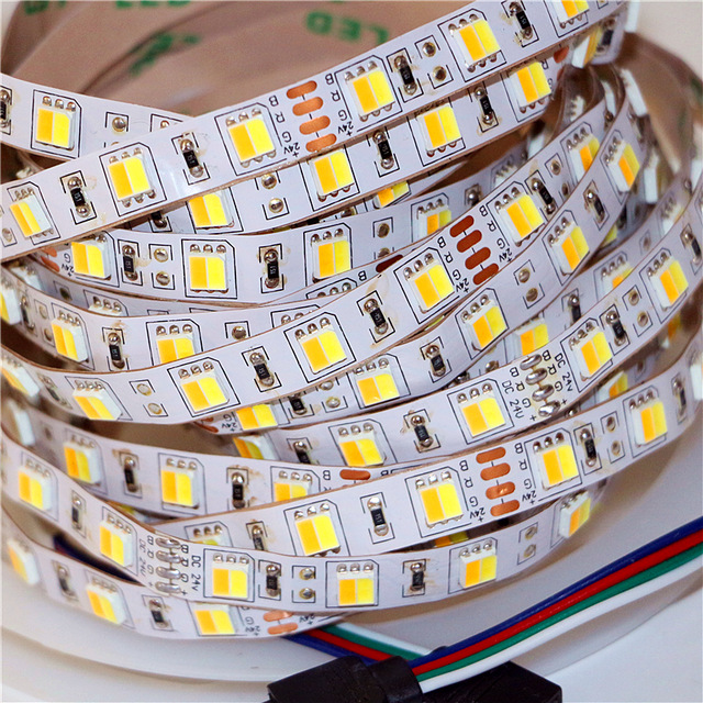
This LEDs are used extensively by IKEA in their lamps. Home assistant has separate control for color temperature, so when you connect IKEA hub to it you can control lamp's warmth.
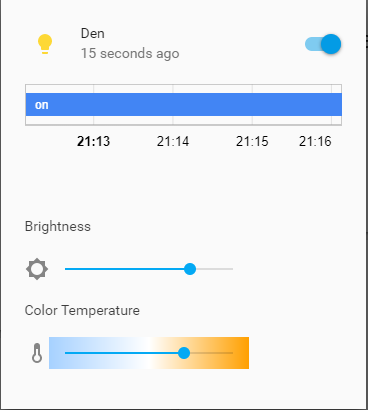
I haven't found suitable message type in Mysensor's API. Is there any way to implement this feature? Or maybe there is some workaround to do this with current API? -
What did you build today (Pictures) ? -
Everything nRF52840@scalz haven't you noticed that mysensors' community which is represented mostly by this forum has become more than just an arduino library? People share on this forum many projects that has only mediate connection to mysensors, if any. And many of users of the library in it's current form have outgrowing some of it's limitations, so naturally they will try to find a solution to overcome them and then share with others on this forum. I don't see nothing wrong for mysensors platform to evolve and adopt modern standards and/or protocols. And even if 15.4 is not suitable or just a replacement of mysensors protocol I think there are people here that will find it useful to read about it. Correct me if I'm wrong but there is no rule against discussing other protocols than mysensors on this forum.
-
nRF5 action!@omemanti It seems like some peripherals are not shut down before sleep. As library you've mentioned uses Wire library, it must be TWI (i2c) interface that are active during sleep and consumes extra power. I'm afraid that you will have to manually disable/enable TWI around sleep routine.
EDIT: I see you've found an answer by yourself. Just want to clarify that it isn't nrf5 chip's fault, it just how it intended to work. It doesn't automagically disable all peripherals during sleep. So, someone should write low current sleep library for nrf5 specifically, that will check the state of peripherals before sleep and disable them if needed. -
Modular sketch to be configured with JSON (idea)@boozz yes, exactly I had this in mind, but with specifics of Mysensors framework. Not everyone wants to rely on WiFi with their home automation.
@mtiutiu I mentioned JSON because I've used JSON library for Arduino and know that it exists, it well may be YAML if it's more suitable.
@user2684 said in Modular sketch to be configured with JSON (idea):
BUT this is defined at compilation time not at runtime as you are suggesting. Reason is simple: since there are 60+ ready-to-use sensors in NodeManager, accommodating everything especially in a small arduino is not feasible, also considering the dependencies some sensors bring in. I see usually up to 3-4 sensors can fit the flash, no more. But I expect in different environments the situation could be different or at least for a subset of those.
We are talking about nRF52 use case, which has abundance of available flash space. And my thought was a bit different then you described.
Imagine you have base firmwares for most sensor types, or it can be generated with NodeManager. But key parameters are configured with externally loaded JSON (or YAML) file, so it can be modified after flashing initial firmware.
I'm not completely sure how much use does this solution has, that's why I started discussion here, to see if anyone thinks it would be a good idea.
Thanks for your reply :) -
What did you build today (Pictures) ?@berkseo thanks for mentioning that. But as I understand the change in software would be just including another header file, if I'm using GxEPD library. There is a mention on github that there is GDEH0154D67 model as a replacement for GDEP015OC. Or do you mean that they are discontinuing 1.54" displays completely?
