Navigation

    • Register
    • Login
    • OpenHardware.io
    • Categories
    • Recent
    • Tags
    • Popular
    1. Home
    2. pansen
    3. Posts
    • Profile
    • Following
    • Followers
    • Topics
    • Posts
    • Best
    • Groups

    Posts made by pansen

    • Howto use myscontroller from node-red-contrib-mysensors?

      Hi,

      @tbowmo maybe you can help with this:

      I would like to use the myscontroller node from node-red-contrib-mysensors to assign and track my node IDs, but I am struggling with the details.

      myscontroller seems to read the incoming msg, but when double clicking on it, id is "undefined".

      Here are the relevant nodes:

      [{"id":"8aa619bf.bcddb8","type":"myscontroller","z":"a8b8ec2f.f6e17","database":"839402cc.e6ba6","name":"node_controller","handleid":true,"timeresponse":true,"timezone":"UTC","measurementsystem":"M","mqttroot":"mysensors-in","x":740,"y":660,"wires":[["ca58e694.77646","da1a60bf.fddd1"]]},{"id":"d1caae4a.7e6d08","type":"mqtt in","z":"a8b8ec2f.f6e17","name":"","topic":"mysensors-out/#","qos":"2","broker":"708db7ae.68d95","x":300,"y":660,"wires":[["4abb49a2.3b382"]]},{"id":"4abb49a2.3b382","type":"mysdecode","z":"a8b8ec2f.f6e17","database":"","name":"","mqtt":true,"enrich":false,"x":530,"y":660,"wires":[["8aa619bf.bcddb8"]]},{"id":"da1a60bf.fddd1","type":"mqtt out","z":"a8b8ec2f.f6e17","name":"","topic":"","qos":"","retain":"","broker":"708db7ae.68d95","x":1020,"y":660,"wires":[]},{"id":"839402cc.e6ba6","type":"mysensorsdb","z":"","name":"test_db_1","file":"/home/blub/test_db_1.sqlite"},{"id":"708db7ae.68d95","type":"mqtt-broker","z":"","name":"mosquitto-betty","broker":"localhost","port":"1883","clientid":"","usetls":false,"compatmode":true,"keepalive":"60","cleansession":true,"birthTopic":"","birthQos":"0","birthPayload":"","closeTopic":"","closeQos":"0","closePayload":"","willTopic":"","willQos":"0","willPayload":""}]
      

      And the relevant sketch code:

      #define MY_DEBUG
      #define MY_RADIO_NRF24
      #include <MySensors.h>
      #define CHILD_ID 1
      //#define MY_PARENT_NODE_ID 0
      //#define MY_PARENT_NODE_IS_STATIC
      #define SN "Worktable RGBW"
      #define SV "1.6"
      [...]
      
      void presentation(){
      	sendSketchInfo(SN, SV);
      	present(CHILD_ID, S_RGBW_LIGHT );
      }


      When I restart the node, it actually gets node id 1, no matter what I do with myscontroller.

      My configure is:

      /configure --spi-spidev-device=/dev/spidev0.0 --my-transport=rf24 --my-rf24-ce-pin=2 --my-rf24-cs-pin=13 --my-rf24-irq-pin=21 --my-gateway=mqtt --my-controller-ip-address=127.0.0.1 --my-mqtt-publish-topic-prefix=mysensors-out --my-mqtt-subscribe-topic-prefix=mysensors-in --my-mqtt-client-id=mysensors --my-mqtt-password=blub --my-port=1883 --my-mqtt-user=mysensors
      

      I think I am just using the wrong topics, setting and combination of nodes.

      When I set the topic in myscontroller to the publish topic, the following message spams my broker:

      mysensors-out/1/255/3/0/6 : msg : Object
      object
      topic: "mysensors-out/1/255/3/0/6"
      payload: "M"
      qos: 0
      retain: false
      _topic: "mysensors-out/1/255/3/0/6"
      _msgid: "f5d62d35.d8df2"
      topicRoot: "mysensors-out"
      nodeId: 1
      childSensorId: 255
      messageType: 3
      ack: 0
      subType: 6
      origin: 2
      messageTypeStr: "C_INTERNAL"
      subTypeStr: "I_CONFIG"
      
      posted in Node-RED
      pansen
      pansen
    • RE: πŸ’¬ Building a Orange Pi Gateway

      Hi,

      for anyone creating a gateway on an Orange Pi PC using armbian mainline (4.x Kernel): The fex modifications are not necessary any more. As noted before by @Roman, the device tree needs to be modified.

      If you use the exact same pins as in this guide for the Orange Pi PC, SPI0 needs to be activated instead of SPI1. (Pi Zero and PC are kind of pin compatible, but Zero only has SPI1 routed to the header, whereas the same pins on the PC have SPI0. On top, the Orange Pi PC also has SPI1 but on other pins):

      verbosity=1
      logo=disabled
      console=both
      disp_mode=1920x1080p60
      overlay_prefix=sun8i-h3
      overlays=w1-gpio uart1 spi-spidev spi-add-cs1
      param_spidev_spi_bus=0
      param_spidev_spi_cs=0
      rootdev=<removed>
      rootfstype=ext4
      usbstoragequirks=<removed>
      

      Attention: Header pin 26 is different between Pi PC and Pi Zero. On the zero it is PA10 but on the PC it is PA21. I connected the interrupt pin of the nrf24 like in the guide (header pin 26) and changed the configure command accordingly.

      So the full command to use SPI0 and the interrupt connected to header pin 26 of the Orange Pi PC is:

      ./configure --spi-spidev-device=/dev/spidev0.0 --my-transport=rf24 --my-rf24-ce-pin=2 --my-rf24-cs-pin=13 --my-rf24-irq-pin=21 --my-gateway=mqtt --my-controller-ip-address=127.0.0.1 --my-mqtt-publish-topic-prefix=mysensors-out --my-mqtt-subscribe-topic-prefix=mysensors-in --my-mqtt-client-id=mysensors
      

      The rest of the guide is still valid, except that the transport is now called "rf24" instead of "nrf24". @mfalkvidd can you correct this maybe? Also, the -d switch seems to be not existing any more.

      posted in Announcements
      pansen
      pansen
    • RE: πŸ’¬ Building a Orange Pi Gateway

      @pii

      • Does /sys/class/gpio/gpio24/direction exists?
      • Does /sys/class/gpio/gpio24 exists?
      • Can you write to them using echo?
      posted in Announcements
      pansen
      pansen
    • RE: πŸ’¬ Building a Orange Pi Gateway

      i'm sorry, i do not have experience with encryption. essentially it depends on the code you want to write, since on the pi you are kind of limited to scripting, whereas microcontroller code is closer to hardware. also, if you need things like an adc or spi you're better of with a microcontroller. if it's just about some LEDs lighting up..

      posted in Announcements
      pansen
      pansen
    • RE: πŸ’¬ Building a Orange Pi Gateway

      If your conditions are

      • 3 LEDs: yes through GPIO
      • Ethernet: yes (d'uh)
      • beefy enough for software encryption: I guess? For an IoT-low data rate scenario for sure

      I'm running armbian on my Orange Pi and setting up mosquitto is a breeze. But you don't need a broker right? Don't forget you need an SD card on top and more power.

      posted in Announcements
      pansen
      pansen
    • RE: πŸ’¬ Building a Orange Pi Gateway

      @awilner I am in a hurry right now so I cannot go through what you wrote in detail, but maybe my post about pin numbering can help you: https://forum.mysensors.org/post/58309 It is related to an OPi Plus2e using nrf24 but the numbering formulas should still be valid.

      Good luck!

      posted in Announcements
      pansen
      pansen
    • RE: Browser-based firmware generator

      Incredible, good job!

      What do you mean bu that though

      @rakeshpai said in Browser-based firmware generator:

      It doesn't work.

      From my perspective it does work πŸ˜‰

      posted in Development
      pansen
      pansen
    • RE: πŸ’¬ LoRa Ra-01 ATmega328P Node

      @NeverDie

      I understand but tend to disagree πŸ˜‰

      posted in OpenHardware.io
      pansen
      pansen
    • RE: πŸ’¬ LoRa Ra-01 ATmega328P Node

      Out of curiousity: Why did you use a through-hole AVR and not a SMD one?

      posted in OpenHardware.io
      pansen
      pansen
    • RE: Can't link rfid node item

      The ID shouldn't matter..

      What is the lock item? Showing the status of the lock?

      Interesting that those get added to your files, for me the items that I add through Paper UI are not reflected in the folder structure, which is quite annoying...

      Checking https://www.mysensors.org/controller and https://www.mysensors.org/download/serial_api_20 it looks like the lock stuff should be fully supported by OH, weird. Did you ask in their forums? It's superactive actually...

      posted in OpenHAB
      pansen
      pansen
    • RE: Has anyone made their own lab power supply out of a PSU?

      Well, if you only need static voltages: 12 and 5 you already have and for 3.3 I'd get LM2596 or XM1584 regulators depending on current needs. But then, this would not really be a lab PSU which is by definition adjustable πŸ˜‰ A common design is the EEVBlog one. Nasty stuff though, I honestly wouldn't do it myself and rather spend the 150EUR...

      posted in Hardware
      pansen
      pansen
    • RE: Any parallel interface accellerometers ?

      SPI can be blazing fast. A colleague of mine recently implemented some memory interface in the range of two/three digit MBits per second. Intuitively I would say bit banging an 8 bit parallel data input using a microcontroller is slower than using high-speed SPI. Just polling the 8 bits from the pins will take ages...Of course I am assuming you're using a uc and not a FPGA.

      You need to be precise, just because you can read data faster doesn't mean you can process it faster. I'd be a bit shocked to hear that an accelerometer could produce more data than a standard uc SPI can take...but then, I also have no experience.

      So I'm also curious what you are planning to do!

      posted in Hardware
      pansen
      pansen
    • RE: Need help with building my first simple mesh

      @mfalkvidd: I agree and know that MySensors is not built upon a mesh topology, however, couldn't each MySensors node act as a repeater for the above use case? I'm not using the repeater stuff so I am curious...

      posted in Development
      pansen
      pansen
    • RE: High current

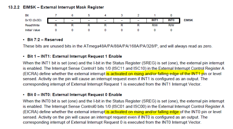
      @gohan @AWI I understand, so the main issue is that CHANGE does not work. I checked the datasheet and INT0 and INT1 can also do CHANGE so it's a bit weird:

      0_1493197213711_upload-fce2880a-1075-44e0-a230-4ed6d513d5db

      Of course you're limited to the INT0/1 pins then.

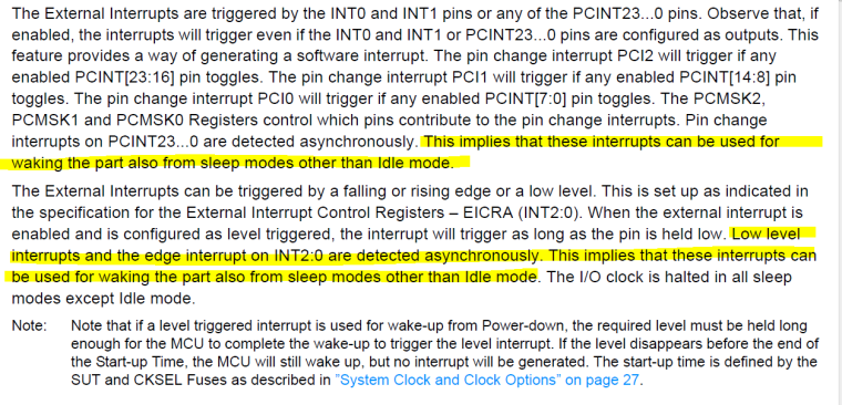
      But also:

      0_1493197914736_upload-f3abb58d-503e-4bfc-abd2-611463f2e019

      So PCINT is just not implemented in MySensors? Code is probably based on an old datahseet:

      0_1493197957731_upload-0d9666b3-298c-4435-b0a0-8ae72415c10a

      Because that's just wrong...Looking at hwSleep for AVR it looks like it's just using attachInterrupt with the passed through mode. I'll test later because in fact I'm working on a project with a MPR121 touch controller that wakes up my Pro Mini on FALLING so I change it to CHANGE and see what happens...

      Anyhow, @kk02067 I'd use INT0/1 pins if you can...also, just measure the current consumption und unplug the nrf to see how much it changes. My mentioned MPR121 project consumes about 0.5-0.9mA in sleep and ~18mA in awake (MPR121+Pro Mini+nrf) just to give you some ballpark numbers. Consumption went to 5mA with nrf unplugged.

      posted in Troubleshooting
      pansen
      pansen
    • RE: High current

      Sorry for OT but I am a bit confused, doesn't support sleep wakeups on pin changes? I guess you mean something else then?

      /**
         * Sleep (PowerDownMode) the MCU and radio. Wake up on timer or pin change.
         * See: http://arduino.cc/en/Reference/attachInterrupt for details on modes and which pin
         * is assigned to what interrupt. On Nano/Pro Mini: 0=Pin2, 1=Pin3
         * @param interrupt Interrupt that should trigger the wakeup
         * @param mode RISING, FALLING, CHANGE
         * @param sleepingMS Number of milliseconds to sleep or 0 to sleep forever
         * @param smartSleep Set True if sending heartbeat and process incoming messages before going to sleep
         * @return Interrupt number if wake up was triggered by pin change, @ref MY_WAKE_UP_BY_TIMER if wake up was triggered by timer, @ref MY_SLEEP_NOT_POSSIBLE if sleep was not possible (e.g. ongoing FW update)
         */
      int8_t sleep(const uint8_t interrupt, const uint8_t mode, const uint32_t sleepingMS = 0,const bool smartSleep = false);
      
      posted in Troubleshooting
      pansen
      pansen
    • RE: RGB LED strip controller with FastLED

      @AWI Ha, I forgot about that...I remembered that you actually need a minimum load on the output of the switching regulator for it to even run. I created a spreadsheet just taking into account the quiescent currents and assuming 70% effciency for the lm2596 (a "bit" optimistic. Datasheet says 80% at 3A load for 12V-5V operation). Quiescent current for the LM2596 is much higher.

      Considering the mini pro takes about 12-20mA running, I am sure to opt for the 7805 or LM317 from now on πŸ˜‰ (If there is nothing else drawing current). I think nano etc are comparable but the FTDI USB to serial converter probably adds some current that the mini pro is missing.

      0_1491471717305_upload-90fd958b-83f1-4af4-abbc-f4103ec1e2fc

      0_1491471734938_analysis7805.xlsx

      posted in My Project
      pansen
      pansen
    • RE: RGB LED strip controller with FastLED

      @AWI Was about to say that πŸ˜‰ For a hobbyist it doesn't matter that much but switching regulators are quite nasty when it comes to EMI.

      @gohan: A good rule of thumb is to assume that the voltage difference from input to output of the linear regulator will be converted to heat. So if you have a high current application or a high voltage difference a switching regulator is better. In case of running an Arduino (let's say it consumes 80mA@5V which is quite high) it's negligible: P=U*I=(12-5)*0.08=0.5W which should be dissipated without heatsink easily.

      edit: ah you just answered yourself ;D

      posted in My Project
      pansen
      pansen
    • RE: RGB LED strip controller with FastLED

      @micah @gohan Yeah I could imagine nasty spikes from a cheap power supply can fry the regulator. I still find an LM2596 overpowered for this. At least take a 7805 πŸ˜›

      posted in My Project
      pansen
      pansen
    • RE: N00b + MQTT gw + openHAB2

      @gohan: I understand but what's the incentive? It's more easy to plug the Arduino via USB and do serial gateway than fiddling with MQTT and network stuff.

      posted in Troubleshooting
      pansen
      pansen
    • RE: N00b + MQTT gw + openHAB2

      I do not fully understand why you are using MQTT. Can you quickly sketch your setup in a block diagram?

      If you want a quick setup for starters, go for

      Laptop <-> Serial Gateway Arduino <-> nrf24 ******** nrf24<->Arduino<->Relay

      then get OH2 up and running. If you use pure MQTT you don't need the MySensors binding because everything is going through the MQTT broker (mosquitto). I recently started playing with MQTT and it is way more complex than above suggested setup because you need to manually play with configs etc.

      I remember I had problems with OH2 because some java stuff was missing/not functioning. See the threads on this forum and the OH2 forums.

      Laptop is suitable, just think about the power consumption. If you let it running 24/7 I'd consider getting a (even older) Raspberry Pi. The costs will be amortized quickly. (Let's say 30W * 24h * 365d * 0.25ct/kWh = 66EUR meaning RPi will be amortized in 6 months).

      posted in Troubleshooting
      pansen
      pansen
    • RE: RGB LED strip controller with FastLED

      I think you might have left out the LM2596 since the Nano linear regulator should be able to cope with 12V.

      posted in My Project
      pansen
      pansen
    • RE: πŸ’¬ Building a Orange Pi Gateway

      @giran hi i don't think you can run the service and the binary standalone at the same time since hardware access is exclusive. Try to stop the service and then run the binary again.

      posted in Announcements
      pansen
      pansen
    • RE: πŸ’¬ Building a Orange Pi Gateway

      Can you post a picture of your wiring?

      posted in Announcements
      pansen
      pansen
    • RE: [SOLVED] MQTT message does not show (MySensors on ESP8266)

      @gohan said in MQTT message does not show (MySensors on ESP8266):

      Have you considered using easy esp or other similar firmware?

      Esay esp won't work for me since it depends on the Arduino IDE but I am using platform.io. Any incentives to change?

      @Yveaux said in MQTT message does not show (MySensors on ESP8266):

      @pansen said in MQTT message does not show (MySensors on ESP8266):

      mosquitto_sub -h localhost -t Sonoff-Out

      Try subscribing to all topics starting with the Sonoff-Out prefix, using a wildcard, and see if that makes a difference:

      mosquitto_sub -h localhost -t Sonoff-Out/#
      

      That was it, thanks!

      0
      1
      0
      1
      0
      1
      2.1.1
      Sonoff PIR Switch
      1.1
      0
      

      edit: and some verbose output for completeness:

      x@x:~$ mosquitto_sub -h localhost -v -t Sonoff-Out/#
      Sonoff-Out/0/73/1/0/2 1
      Sonoff-Out/0/73/1/0/2 0
      
      posted in Troubleshooting
      pansen
      pansen
    • [SOLVED] MQTT message does not show (MySensors on ESP8266)

      Hi,

      I put the below code on a Sonoff switch (which has an ESP8266 on it). I installed mosquitto as MQTT broker on my orange pi and tested it, so the broker is ok.

      Now, when I subscribe to the topic I set, nothing is shown when my relay state changes:

      mosquitto_sub -h localhost -t Sonoff-Out
      

      I am sure I am just missing some configuration or a command...Any ideas?

      main.h

      #define PIN_PIR_SENSOR 14
      #define PIN_RELAY  12
      #define PIN_LED 13
      #define RELAY_ON 1
      #define RELAY_OFF 0
      #define LED_ON 0
      #define LED_OFF 1
      
      #define CHILD_ID 73
      
      // Enable debug prints to serial monitor
      #define MY_DEBUG
      
      // Use a bit lower baudrate for serial prints on ESP8266 than default in MyConfig.h
      #define MY_BAUD_RATE 115200
      
      #define MY_GATEWAY_MQTT_CLIENT
      #define MY_GATEWAY_ESP8266
      
      #define MY_ESP8266_SSID "REMOVED"
      #define MY_ESP8266_PASSWORD "REMOVED"
      #define MY_ESP8266_HOSTNAME "Sonoff-PIRSwitch-Lamp"
      
      //#define MY_IP_ADDRESS 1,1,1,80
      //#define MY_IP_GATEWAY_ADDRESS 1,1,1,10
      //#define MY_IP_SUBNET_ADDRESS 255,255,255,0
      
      //#define MY_USE_UDP
      #define MY_CONTROLLER_IP_ADDRESS 1,1,1,1
      
      // The port to keep open on node server mode
      #define MY_PORT 1883
      
      // How many clients should be able to connect to this gateway (default 1)
      //#define MY_GATEWAY_MAX_CLIENTS 1
      
      // Set this node's subscribe and publish topic prefix
      #define MY_MQTT_PUBLISH_TOPIC_PREFIX "Sonoff-Out"
      #define MY_MQTT_SUBSCRIBE_TOPIC_PREFIX "Sonoff-In"
      
      // Set MQTT client id
      #define MY_MQTT_CLIENT_ID "Sonoff-PIRSwitch-Lamp"
      
      #if defined(MY_USE_UDP)
      #include <WiFiUdp.h>
      #endif
      
      #include <Arduino.h>
      //#include <ESP8266mDNS.h>
      #include <ESP8266WiFi.h>
      #include <MySensors.h>
      
      void setup();
      void loop();
      void present();
      void receive(const MyMessage &message);
      void ISR_PIRPinHasChanged();
      void SetRelayAndLedStatus();
      void ToggleRelay();
      void TransmitStatusToController();
      

      main.cpp

      #include "main.h"
      
      int currentRelayStatus;
      MyMessage msg(CHILD_ID,V_STATUS);
      
      void setup(){
        pinMode(PIN_LED, OUTPUT);
        pinMode(PIN_RELAY, OUTPUT);
        pinMode(PIN_PIR_SENSOR, INPUT);
      
        currentRelayStatus = RELAY_OFF;
        attachInterrupt(PIN_PIR_SENSOR, ISR_PIRPinHasChanged, RISING);
      
        //flash led
        digitalWrite(PIN_LED,LED_ON);
        delay(100);
        digitalWrite(PIN_LED,LED_OFF);
        delay(100);
        digitalWrite(PIN_LED,LED_OFF);
        delay(100);
        digitalWrite(PIN_LED,LED_OFF);
        delay(100);
      }
      
      void loop()
      {
      
      }
      
      void presentation()  {
        // Send the sketch version information
        sendSketchInfo("Sonoff PIR Switch", "1.1");
        // Register sensor
        present(CHILD_ID, S_BINARY);
        SetRelayAndLedStatus();
        TransmitStatusToController();
      }
      
      void receive(const MyMessage &message)
      {
        if (message.type==V_STATUS  && message.sensor==CHILD_ID) {
          if(message.getBool() == true)
          {
            currentRelayStatus = RELAY_ON;
          }
          else{
            currentRelayStatus = RELAY_OFF;
          }
          SetRelayAndLedStatus();
          TransmitStatusToController();
        }
      }
      
      
      void ISR_PIRPinHasChanged(){
        int currentPinStatus = digitalRead(PIN_PIR_SENSOR);
        if(currentPinStatus == LOW){
          Serial.println("ISR fired, pin LOW");
        }
        else{
          Serial.println("ISR fired, pin HIGH");
          ToggleRelay();
        }
      }
      
      void ToggleRelay(){
        if(currentRelayStatus == RELAY_ON){
          Serial.println("toggling relay to OFF");
          currentRelayStatus = RELAY_OFF;
        }
        else{
          Serial.println("toggling relay to ON");
          currentRelayStatus = RELAY_ON;
        }
        SetRelayAndLedStatus();
        TransmitStatusToController();
      }
      
      void SetRelayAndLedStatus(){
        if(currentRelayStatus == RELAY_ON){
          Serial.println("switching on");
          digitalWrite(PIN_LED, LED_ON);
          digitalWrite(PIN_RELAY, RELAY_ON);
        }
        else{
          Serial.println("switching off");
          digitalWrite(PIN_LED, LED_OFF);
          digitalWrite(PIN_RELAY, RELAY_OFF);
        }
      }
      
      void TransmitStatusToController(){
        Serial.println("sending status to controller");
        if(currentRelayStatus == RELAY_ON){
          send(msg.set(true));
        }
        else{
          send(msg.set(false));
        }
      }
      
      posted in Troubleshooting
      pansen
      pansen
    • RE: NRF24L01+ wie an ATtiny167 (Digisparc Pro) anschließen

      @mfalkvidd He's asking how to connect a nrf24 to an ATtiny167 and, if needed, what to tell MySensors to make it work.

      @Oskar-DΓΌnnebeil Compare the pinouts, here's the ATtiny. Then connect it 1:1 if possible. I know of the options MY_CE_PIN and MY_CS_PIN, maybe there are more. Check the guides for that.

      posted in Troubleshooting
      pansen
      pansen
    • RE: Sonoff Wifi Switch, GPIO14 and interrupts

      can you post some code? interrupts work fine with my sonoff:

      attachInterrupt(PIN_PIR_SENSOR, ISR_PIRPinHasChanged, CHANGE);
      [...]
      void ISR_PIRPinHasChanged(){
        int currentPinStatus = digitalRead(PIN_PIR_SENSOR);
        if(currentPinStatus == LOW){
          Serial.println("ISR fired, pin LOW");
        }
        else{
          Serial.println("ISR fired, pin HIGH");
          ToggleRelay();
        }
      }
      
      ISR fired, pin LOW
      ISR fired, pin HIGH
      toggling relay to OFF
      switching off
      sending status to controller
      ISR fired, pin LOW
      ISR fired, pin HIGH
      toggling relay to ON
      switching on
      sending status to controller
      ISR fired, pin LOW
      ISR fired, pin HIGH
      toggling relay to OFF
      switching off
      
      posted in Hardware
      pansen
      pansen
    • RE: πŸ’¬ Building a Orange Pi Gateway

      Hi @SdeWeb header pins 8 and 10 are used by some other hardware (SPI1, UART3) which might need to be deactivated in the .fex in your system, for me it worked straight away so that would be weird..just check the .fex if SPI1 and UART3 are indeed disabled.

      It looks like the definitions for the GPIO are faulty, you could try a LED test to see if they work at all. If the problem persists rather open a topic in the Development sub forum 😎 Or, pick another GPIO, for example header pins 14 and 16.

      posted in Announcements
      pansen
      pansen
    • RE: Output voltage problem with StepUp Booster 3.3V

      true, they actually need some minimum load to function properly but the datasheet does not mention anything about it..

      posted in Hardware
      pansen
      pansen
    • RE: Output voltage problem with StepUp Booster 3.3V

      what is written on the chip? looking at the datasheet there's versions ranging between 3.0 up to 6.0V in 0.1V steps:

      0_1488137189554_upload-755af1ee-fb2d-4c15-9db3-6428fdb49a42

      posted in Hardware
      pansen
      pansen
    • RE: πŸ’¬ MySensors Contest 2017

      @FotoFieber said in πŸ’¬ MySensors Contest 2017:

      Maybe a 3d printing project with my 8 year old daughter?

      I don't want to drive you out of the competition but go for that, trust me, she'll appreciate it πŸ˜‰

      posted in Announcements
      pansen
      pansen
    • S_RGBW appearing with V_VAR1 etc instead V_RGBW

      Hi,

      when I present my sketch like this:

      present(CHILD_ID_RGBW, S_RGBW_LIGHT);
      

      OpenHAB2 recognizes the node, but it doesn't show V_RGBW:

      0_1488033721788_upload-dd6f6c3e-361b-405f-a7dd-274c38a6ac7f

      I am using version 2.1.1. on the node and the development branch on the controller.

      Is this intended?

      posted in Troubleshooting
      pansen
      pansen
    • RE: πŸ’¬ MySensors Contest 2017

      Phew, May, better stop being lazy and get going πŸ˜€

      posted in Announcements
      pansen
      pansen
    • RE: Add new V_ACTION behavior for window shade/cover (and perhaps others)

      Why, just always send V_STATUS=ON and implement it properly in your node (i.e. toggle on reception).

      posted in Feature Requests
      pansen
      pansen
    • RE: Add new V_ACTION behavior for window shade/cover (and perhaps others)

      I find V_ACTION too generic and would rather name it V_TRIGGER or something. Besides that I find the idea quite nice!

      posted in Feature Requests
      pansen
      pansen
    • RE: Node not sending updates, probably some problem with my sketch

      @AWI: so in this case SLEEP_TIME actually overflows?

      posted in Development
      pansen
      pansen
    • RE: Odroid c1 as getaway?

      Yes, SPI pins should not light. I am at the end of my knowledge here, sorry. Next step would be connecting an oscilloscope to see it anything omes out the SPI interface and the selected pins.

      posted in Hardware
      pansen
      pansen
    • RE: MyController on OrangePi

      You should create a new topic for that..can you post the guides you are using? I'm not using MyController in productive environment since it is still very young. Maybe try OpenHAB or domoticz if you are a Linux noob?

      posted in MyController.org
      pansen
      pansen
    • RE: Nice cases/housings for projects

      Thanks, IKEA is indeed a good inspiration source!

      posted in Enclosures / 3D Printing
      pansen
      pansen
    • RE: Stepper wont work with Mysensors

      Code looks good so far... (you misplaced the starting and ending ``` to mark code in a black box).

      What I can tell you from own, painful experience: If anything fails with the radio setup (also registration I think), loop() will never be executed. I was testing a LED library, working perfectly without MySensors.h but not doing anything with MySensors.h included.

      Later I realized my controller was switched off..after I switched it on everything worked. So ensure that MySensors can communicate properly. That means implementing presentation() and all other functions..

      posted in General Discussion
      pansen
      pansen
    • RE: Stepper wont work with Mysensors

      Hi,
      we need

      • Schematic
      • Code
      • Relevant links to the used parts i.e. datasheets
      posted in General Discussion
      pansen
      pansen
    • RE: Odroid c1 as getaway?

      I don't know. Looked at the code, these are my conclusions:

      RF24.cpp

      LOCAL void RF24_csn(const bool level)
      {
      	hwDigitalWrite(MY_RF24_CS_PIN, level);
      }
      
      LOCAL void RF24_ce(const bool level)
      {
      	hwDigitalWrite(MY_RF24_CE_PIN, level);
      }
      

      MY_RF24_CS_PIN and MY_RF24_CE_PIN are supposedly set by ./configure

      hwDigitalWrite leads to MyHwLinuxGeneric.cpp

      
      void hwDigitalWrite(uint8_t pin, uint8_t value)
      {
      	digitalWrite(pin, value);
      }
      

      which leads to GPIO.cpp

      void GPIO::digitalWrite(uint8_t pin, uint8_t value)
      {
      	FILE *f;
      	char file[128];
      
      	if (pin > lastPinNum) {
      		return;
      	}
      	if (0 == exportedPins[pin]) {
      		pinMode(pin, OUTPUT);
      	}
      
      	sprintf(file, "/sys/class/gpio/gpio%d/value", pin);
      	f = fopen(file, "w");
      
      	if (value == 0)	{
      		fprintf(f, "0\n");
      	} else {
      		fprintf(f, "1\n");
      	}
      
      	fclose(f);
      }
      

      As you can see, the pin numbers you chose have to coincide with the "file" mentioned here:

      sprintf(file, "/sys/class/gpio/gpio%d/value", pin);
      

      If you're not sure, the already mentioned LED test can help by switching on/off the concerned "files".

      posted in Hardware
      pansen
      pansen
    • RE: Odroid c1 as getaway?

      Yes, an LED with a resistor. Then try to turn it on and off. But maybe that is not even necessary.

      Besides, the pin numbers you mentioned seem quite odd, but I do not have experience with the C1.
      Considering this image", your nrf24 has to be connected to header pins 19,21,23,1 for MOSI,MISO,SCK,3V3 and any GND one. Since you connected the two remaining ones on 100 and 101, try first to modify your configure to

      ./configure --spi-spidev-device=/dev/spidev0.0 \
              --my-transport=nrf24 --my-rf24-ce-pin=22 --my-rf24-cs-pin=21
      

      Which are the WiringPi pin numbers.

      let me know if it works.

      posted in Hardware
      pansen
      pansen
    • Nice cases/housings for projects

      Hi all,

      since my current projects are still dangling in the open: what kind of (nice) case/housings can you recommend? The standard electro-installation grey box might be convenient but also very ugly.

      Inspired by this kickstarter, I am thinking of creating a wall mounted controller from wood and maybe even duplicate the remote from the kickstarter. However, I have zero woodworking experience, besides using an axe and a saw...Any resources on this are appreciated, dremel-clone is available πŸ‘

      tl;dr: Looking for nice boxes or similar, DIY or off-the-shelf to put my projects in!

      Cheers,
      pansen

      posted in Enclosures / 3D Printing
      pansen
      pansen
    • RE: LED Lamp

      @Yveaux said in LED Lamp:

      @hek how about adding this to the build-page?

      +1

      Nice one, would you also share the code? I'm interested in the effects for future projects...

      posted in My Project
      pansen
      pansen
    • RE: Odroid c1 as getaway?

      @dantefff are you sure the pin numbers are correct? can you connect a LED and test if it's the right numbers?

      posted in Hardware
      pansen
      pansen
    • RE: German users

      @marceltrapman German, living and working in Holland (Zuid Holland to be precise) πŸ˜ƒ

      posted in General Discussion
      pansen
      pansen
    • RE: Creating a wireless fingerprints sensor !

      Hi Ziip,

      • Fingerprint sensors are not secure. The German chaos computer club has demonstrated several times that copies can be produced that will trigger a false positive. I personally would go for a PIN based solution or use a RFID-dongle.
      • You probably can go with z-wave, but you will pay much more.
      • You can mix protocols. I.e. use mysensors for your FPR+arduino+arduino GW and z-wave for the rest. MySensors offers signing of messages and therefore has built-in security. To be honest, MySensors is probably more secure since it is open source. But I also hate security by obscurity, so...
      • If you want pure z-wave, just couple any z-wave sensor with your FPR, for example with the mentioned z-uno module.

      Cheers

      posted in Hardware
      pansen
      pansen
    • RE: Using debounce twice in the same sketch

      No worries. Can you upload a schematic? Like, what is connected where?

      As a start:

      Change 1

      Bounce debouncer = Bounce();  
      

      to

      Bounce debouncer_door_sensor = Bounce();
      

      Change 2

       // After setting up the button, setup debouncer
       debouncer.attach(DOOR_SENSOR);
       debouncer.interval(5);
      

      to

       // After setting up the button, setup debouncer
       debouncer_door_sensor.attach(DOOR_SENSOR);
       debouncer_door_sensor.interval(5);
      

      Change 3

      debouncer.update();
      // Get the update value
       int value = debouncer.read();
      

      to

      debouncer_door_sensor.update();
      // Get the update value
       int value = debouncer_door_sensor.read();
      

      Good luck

      posted in Development
      pansen
      pansen
    • RE: Problem with mysensor library on Arduino IDE Running on Raspi

      Hi,

      please translate anything into English. not everyone understands Dutch.

      Why don't you try what @tbowmo suggested? His steps are quite clear... Besides, you are trying to install a version which is 2 major versions behind the newest one.

      posted in Troubleshooting
      pansen
      pansen
    • RE: Heating - review my schema

      Arduino Uno comes with bootloader no? So programmer is not super-necessary but jus 1 or 2 money anyways.

      Can you directly drive the relay card with the Arduino?

      posted in General Discussion
      pansen
      pansen
    • RE: MySensors Gatway dimmers & Home assistant

      I'm confused, your arduino node is connected to something via serial?

      posted in Hardware
      pansen
      pansen
    • RE: Including "MySensors.h" in multiple files

      @user2684 said in Including "MySensors.h" in multiple files:

      @pansen to you point include guards do not solve the problem here since the error is coming from the linker, not from the compiler.

      Ah right, thanks!

      posted in Development
      pansen
      pansen
    • RE: Is there an easier way to compare the voltages of these two sensors?

      Smaller than 10% of what? 10% of value A will be different than 10% of value B.

      The part you posted is an I2C temperature sensor, not sure what you mean by "reading a voltage value" therefore.

      posted in Hardware
      pansen
      pansen
    • RE: MySensors Gatway dimmers & Home assistant

      Hm not sure. Put some Serial.pintln debug messages to see what actually happens.

      posted in Hardware
      pansen
      pansen
    • RE: Including "MySensors.h" in multiple files

      You can use include guards (just learned that expression myself πŸ˜‰ )

      https://en.wikipedia.org/wiki/Include_guard

      So just put

      #ifndef MYSENSORS_H
      #define MYSENSORS_H
      #include <MySensors.h>
      #endif
      

      instead of just

      #include <MySensors.h>
      

      you might also try #pragma once not sure if the arduino compiler understands it.

      Weird that MySensors.h does not have that in there...

      edit: it actually does...

      /**
       * @file MySensors.h
       *
       * MySensors main interface (includes all necessary code for the library)
       */
      #ifndef MySensors_h
      #define MySensors_h
      
      posted in Development
      pansen
      pansen
    • RE: Exit status 1 Error compiling for board Arduino Nano ?????

      The problem is

      avr-g++: error: CreateProcess: No such file or directory
      

      Without any code we won't be able to help. It looks like a header is missing.

      posted in Troubleshooting
      pansen
      pansen
    • RE: Using debounce twice in the same sketch

      said in Using debounce twice in the same sketch:

      'Bounce debouncer [7]

      Agree with @blacey, however, the problem is that one portion of the code uses

      Bounce debouncer [7]
      

      Whereas the other uses

      Bounce debouncer
      

      It might be enough to remove this declaration and replace

      debouncer
      

      with

      debouncer[0]
      

      in the code using the non-array debouncer class. I do not know your hardware setup, so the index (the zero) might be different.

      posted in Development
      pansen
      pansen
    • RE: MyExtension

      Nice work but please considering giving it a better name than "MyExtension" πŸ˜‰

      posted in Development
      pansen
      pansen
    • RE: Node not sending updates, probably some problem with my sketch

      Hi,

      • Do you actually want to put it to sleep and what does that imply? Is the nrf24 switched off? I'd try it with delay() and see if that influences anything.
      • Is the serial monitor dead too? Put some debug messages after the sleep() function
      • This code uses sensor.sleep() instead of sleep(), dunno if that makes a difference.

      Good luck,
      pansen

      posted in Development
      pansen
      pansen
    • RE: How to build raspberry gw 2.0.0

      For ethernet gateway listening on 0.0.0.0 (i.e. on all interfaces) and port 5003 you can try:

      ./configure --spi-spidev-device=/dev/spidev0.0 --my-transport=nrf24 --my-rf24-ce-pin=13 --my-rf24-cs-pin=14
      

      Check for

      • Check for existance of spidev0.0 and replace if necessary
      • Also check the pin numbers, CE has to be physical pin 8, CN has to be physical pin 10.

      Also you need the latest dev version from git as far as I know.

      For more info check my comment here: https://www.mysensors.org/build/orange

      @martinhjelmare: whats the difference between the virtual one and the "real" one?

      posted in Troubleshooting
      pansen
      pansen
    • RE: How to build raspberry gw 2.0.0

      What's your ./configure command? Can you post a picture/photo of your wiring?

      posted in Troubleshooting
      pansen
      pansen
    • RE: Serial Gateway connect problem ttyAMA0

      Maybe it's a rights problem, can you sudo minicom it? Your domoticz user should be added to the group allowing access to ttys. For me it's group uucp.

      posted in Domoticz
      pansen
      pansen
    • RE: lm2596 + LED + Arduino PWM

      @mfalkvidd: I just finished version 2 of a prototype, when It is working like I want I will present it in the "Projects" subforum πŸ‘

      posted in Troubleshooting
      pansen
      pansen
    • RE: lm2596 + LED + Arduino PWM

      @mfalkvidd Good idea with FastLED, I will use it directly since there is enough space left.

      I use this module, looks like it has a 220uF output cap. Doing some back of the envelope calculations, the time constant (i.e 67% charge point) is about 220us, Arduino PWM frequency is 62.5kHz which yields a resolution of 16us and a total period of 4080us...that's less than 20 times the time constant of the cap.

      So this might actually be the problem! I'll try to lower the PWM frequency and see what happens. In the datasheet they mention you should use a low ESR cap to for a low output ripple, but I don't really care about that in this application, so in the worst case I just switch the output cap with an off the shelf cap with lower capacitance.

      Thanks for your input.

      posted in Troubleshooting
      pansen
      pansen
    • lm2596 + LED + Arduino PWM

      Hi,

      this is more a generic question: I unsoldered the on/off pin of the lm2596 on a module I bought from China. This one then got connected to pin 6 (timer 0 PWM) of an Arduino nano.

      The brightness control (via analogWrite) is working, however, the apparent brightness does not change much for duty cycles higher than 50/255...So I set 0,1...16 and then it is basically already at max brightness.

      • Are there any tricks/formulas to put the apparent brightness between 0-100% for usage directly with a V_DIMMER?
      • Does the lm2596 have a startup time which might affect the PWM?
      • Could I use timer 1 to have a 16-bit PWM or do I scree up MySensors then?

      Cheers,
      pansen

      posted in Troubleshooting
      pansen
      pansen
    • RE: PCB design with nRF24L01 and Arduino Pro Mini

      Unfortunately I am not a PCB designer..I would advise you to ask this question (and also why the boards does not work) on a dedicated electronics forum. EEVBlog forums are very good for that purpose.
      Good luck!

      P.S.: I guess you also tried different nrf24 boards right?

      posted in Hardware
      pansen
      pansen
    • RE: Paying peanuts

      Good to know and good to hear. Have fun with your projects!

      posted in Hardware
      pansen
      pansen
    • RE: PCB design with nRF24L01 and Arduino Pro Mini

      Hmmm looks good, very strange indeed. Is it maybe the ground plane? A problem with your gateway?

      posted in Hardware
      pansen
      pansen
    • RE: Paying peanuts

      Ohh right, the nano, my head spins only around the mini pro at the moment. Sorry ^^

      Could you solve your problem?

      posted in Hardware
      pansen
      pansen
    • RE: Paying peanuts

      Are they both 3.3V? nrf24 needs 3.3V power supply..

      posted in Hardware
      pansen
      pansen
    • RE: PCB design with nRF24L01 and Arduino Pro Mini

      Also the schematic would be helpful! Do you have equipment to check the air interface? (i.e. oscilloscope, spectrum analyzer)

      Did you play with the power level of the nrf24?

      posted in Hardware
      pansen
      pansen
    • RE: Connect Serial Gateway to Openwrt routers TX RX pins

      Does the MySensors gateway + domoticz already run on your router? Then I would say yes, just tell mysgw that your serial gateway is /dev/ttyXXX (whatever your router serial port is).

      posted in Hardware
      pansen
      pansen
    • RE: JULA motion LED hack

      Ohh haha ok now I get it.

      Nice!

      posted in My Project
      pansen
      pansen
    • RE: JULA motion LED hack

      Soooo what does it do?

      posted in My Project
      pansen
      pansen
    • RE: My projects with mysensors on my house

      Nice! Can you share a bit on how to print PCBs with a 3D printer? Is it complex?

      posted in My Project
      pansen
      pansen
    • RE: Is my project possible with MySensors?

      @frazzle said in Is my project possible with MySensors?:

      Why would arduino be better as a gateway?

      If you connect the nrf24 via SPI it will be emulated as an ethernet gateway, and I assume it is more complicated than using a serial gateway (i.e. Arduino) which you directly send commands to, via ttyUSBx. No experience in that though, maybe it is worth to dig a bit more.

      posted in Development
      pansen
      pansen
    • RE: Is my project possible with MySensors?

      Hi,

      I think it is possible. However, in your special case I would rather implement something from the scratch since you do not really need MySensors here (except maybe for signing messages and the WebGUI but you said no controller so..).

      There are nrf24 libraries floating around in the web, probably also some signing functionality I would suppose.

      For sending messages to your network, I'd just put another arduino to the RPi and use the serial port.

      So answering your questions:

      • Implement yourself, for MySensors I don't know
      • See above. MySensors has some signing capabilties afaik
      • Datasheet p24 describes the "received power detector (RPD)" which in the end is a register that can be read out.

      Hope that helps

      posted in Development
      pansen
      pansen
    • RE: πŸ’¬ Building a Orange Pi Gateway

      @lecintre: avec plaisir πŸ™‚ I only compared OpenHAB and domoticz so far. Domoticz worked out of the box with the nrf24 but does not have support for my 5.1 receiver (which OpenHAB does). Jeedom looks to commercial (for example no free app+controller) for my taste and there seems to be no community. A good starting point for me was the popularity of each controller in this forum: https://forum.mysensors.org/category/3/controllers

      I guess it really depends on your application, if you only have DYI sensors and actuators, domoticz is probably enough.

      posted in Announcements
      pansen
      pansen
    • RE: Noob questions: MQTT, openhab, Orange Pi, Arduino

      Thanks @LastSamurai, indeed I only needed to restart the node to see the message.
      Turns out directly connecting the nrf24 via SPI acts like an Ethernet gateway listening on all interfaces on port 5003. (This information was new to me).

      Regarding MQTT: I tried Openhab, but it did not work out of the box with the Ethernet gateway, so I quickly tried domoticz and the SPI-nrf24 worked straight away. Could I have domoticz and OpenHAB (for my 5.1 receiver) running at the same time and communicating via MQTT?

      Regarding internet access: No, I actually do not want to expose any actuators but maybe sensors (HVAC, alarms). But this is low prio.

      posted in OpenHAB
      pansen
      pansen
    • RE: πŸ’¬ Building a Orange Pi Gateway

      @lecintre: I just installed domoticz and I could enable my gateway by clicking on "please setup your Hardware" in the start screen, then selecting "mysensors gateway with lan interface" with the lan ip of my orange pi (but i guess 127.0.0.1 would also work) and port 5003.
      this should appear then:
      mysensors_lan_gw Yes MySensors Gateway with LAN interface
      Version: 2.2.0-beta Setup 0.0.0.0 5003 Disabled

      clicking on "Setup" then leads to a menu where i see my first test node:

      NodeID
      Name
      Sketch Name
      Version
      Children
      Last Seen
      0 Unknown Unknown 1.0 1 2017-01-29 20:27:28
      1 Unknown nrf24LEDtest 1.0 2 2017-01-29 20:28:27

      let me know if that works out for you

      posted in Announcements
      pansen
      pansen
    • RE: πŸ’¬ Building a Orange Pi Gateway

      @marceloaqno: ok so here are my conclusions:
      After going through the schematics of the OPi Plus2e I realized that the H3 has dedicated pins for NAND/eMMC, which is probably not the case for the H2+ in the OPi zero. They used the pins of SPI1 for a status LED and a "MUTE" net, which is not connected anywhere so at first I was like "wtf?"...
      So, the SPI0 is free for usage out of the box and the .fex does not need to be modified. Summed up:

      If the OPi to be used has "SPI0" in the GPIO header, no .fex modifications are necessary. CE and CN/CS/CSN pin can be chosen freely (?), I picked it like this:
      ce - gray - pa13 - PHYSICAL pin8 - LOGICAL pin13 (1-1)*32 + 13
      cn - blue - pa14 - PHYSICAL pin10 - LOGICAL pin14 (1-1)*32 + 14
      If another pin is chosen, the pin number can be calculated with that formula: (position of letter in alphabet - 1) * 32 + pin number (from: https://linux-sunxi.org/GPIO)
      The pinout of the connector can be found here: https://linux-sunxi.org/Xunlong_Orange_Pi_Plus_2E#Expansion_Port (SPI0 pins are PC0-PC2 or 19,21,23)
      After connecting the physical pins 8,10,19,21 and 23 to the nrf24 (and pin 1 for 3.3v), following command was sufficient to set up mysgw and get the nrf24 to respond:
      ./configure --spi-spidev-device=/dev/spidev0.0 --my-transport=nrf24 --my-rf24-ce-pin=13 --my-rf24-cs-pin=14

      posted in Announcements
      pansen
      pansen
    • Noob questions: MQTT, openhab, Orange Pi, Arduino

      Hi all,

      so, I am a bit confused and before implementing in the dark I thought I'd ask for some clarification.

      My setup:

      Orange Pi with

      • MySensor dev branch, with service running in the background
      • nrf24 connected via SPI (sudo ./bin/mysgw -d shows succesful communication with it)
      • Openhab2 installed an running (already controlling my Yamaha receiver)

      Arduino with

      • nrf24 connected like in the guide on this very site
      • running some MySensors demo code for dimming a connected LED (from the platformio site)

      My questions

      • I only need to install the openHab binding from here to see the Arduino-LED test thingy in openHab?
      • What would I need a MQTT gateway for? Because technically it is a serial gateway no? (since SPI is a serial protocol) Or does serial gateway only mean RS232?
      • What would be the advantage of a MQTT gateway?
      • I have read about an openHab cloud service which allows you the control/checking via Internet. Should I use this cloud service or try to expose the orangePi via DDNS?

      Thanks already!
      pansen

      posted in OpenHAB
      pansen
      pansen
    • RE: HELP!! NODE WITH RELAY VOLTAGE AND DETECTOR
      • I NEED HELP!!!! is not a question. Describe your problem and then we might be able to help.
      • Please rewrite this sentence: "The problem is that the only solution for the installation of the coupling relay with a switch." I do not understand it at all. Better use google translate if your English is not so good.
      • You wrote something about asynchronously, I do not see any interrupts so your code is fully synchronous.
      posted in Development
      pansen
      pansen
    • RE: πŸ’¬ Building a Orange Pi Gateway

      @marceloaqno: I'm in the process of enabling SPI1 (and nrf24 subsequently) on the OPI Plus2e and it seems there are some hardware modifications necessary...I'd like to document on the way and when I am finished submit it somehow so it can be included here. Any suggestions for that?

      posted in Announcements
      pansen
      pansen
    • RE: Use dev branch in controller, release for nodes?

      thanks @mfalkvidd , I'll post again if I run into problems!

      posted in Development
      pansen
      pansen
    • Use dev branch in controller, release for nodes?

      Hi,

      as soon as I get my nrf24 modules, I'd like to create below setup. As controller I already put openHAB 2.0 on the orange pi.
      My question: can I use the dev branch on the orange pi (for having SPI, see big topic about orange pi in this forum) and the "normal" branch for programming the Arduino? I would like to use platformIO.org as an IDE for the nodes and they integrated only the "release" branch in their ecosystem (obviously...)

      0_1485176338342_upload-abaeec99-c528-4230-bbfb-c5d06c595c3f

      posted in Development
      pansen
      pansen
    • RE: Gateway all in one

      @gloob: maybe create a pull request? or see if there is/was already one?

      posted in Hardware
      pansen
      pansen
    • RE: Gateway all in one

      @pepson: elaborate on what you are trying to achive.
      @gloob: good point, having had a quick look at the code it might actually be difficult.

      posted in Hardware
      pansen
      pansen
    • RE: Gateway all in one

      did you even read what i wrote? do you expect us to do all the work for you?

      @gloob: yup that makes sense and is possible right, just daisychain the SPI?

      posted in Hardware
      pansen
      pansen
    • RE: Gateway all in one

      so you want your arduino to be able to communicate via 2.4Ghz ISM and RS485?

      nRF24 is clear I suppose, here's a RS485 converter: https://www.aliexpress.com/item/MAX485-Module-RS-485-TTL-to-RS485-MAX485CSA-Converter-Module-For-Arduino-Integrated-Circuits-Products/32667981058.html?spm=2114.30010308.3.2.8EVUDq&ws_ab_test=searchweb0_0,searchweb201602_4_10065_10068_10000009_10084_10000025_10083_10080_10000029_10082_10081_10000028_10110_10111_10060_10112_10113_10062_10114_10056_10055_10037_10054_10033_10059_10032_10099_10078_10079_10000022_10077_10000012_10103_10073_10102_10000015_10096_10000018_10000019_10052_10053_10107_10050_10106_10051-10037_10077,searchweb201603_3,afswitch_2_afChannel,single_sort_1_default&btsid=841ccfaa-2de4-4936-aa67-4a29be1ceebd

      posted in Hardware
      pansen
      pansen
    • RE: Gateway all in one

      Can you elaborate? For now we only know that you want to have those four parts in your design.

      SPI can be daisychained, I do not understand why you want lower and upper ISM though since one should be enough...

      posted in Hardware
      pansen
      pansen
    • RE: Mysensors Gateway on OrangePi (Zero) (opi)

      out of curiousity: this all relates to 3.x kernel in armbian right? which has proprietary stuff in there?

      i read somewhere that mainline 4.10 SPI is "work in progress"

      posted in Development
      pansen
      pansen
    • RE: Mysensors Gateway on OrangePi (Zero) (opi)

      @marceloaqno: are you planning to create a pull request? also, like @Reza suggested i think it would be smart to gather all information somehwhere, unfortunately mysensors does not seem to have a wiki. can we write an article somehow? i could take care of that.

      posted in Development
      pansen
      pansen
    • RE: Mysensors Gateway on OrangePi (Zero) (opi)

      @hausinger: try to change

      ./configure --my-gateway=serial --my-serial-port=/dev/USB0 --my-serial-baudrate=115200
      to
      ./configure --my-gateway=serial --my-serial-port=/dev/ttyUSB0 --my-serial-baudrate=115200

      Be aware that USB devices are enumerated in the order they have been plugged in, so you cannot rely 100% on the arduino being "0".

      @mihai-aldea: haha I didn't even consider this. are there any disadvantages except for the increased power consumption? (and slightly higher cost)

      posted in Development
      pansen
      pansen
    • RE: Mysensors Gateway on OrangePi (Zero) (opi)

      Great info indeed, thanks! I will join the effort again when the OPi+nRF24 arrived. Just compiling without any hardware feels like baking a cake and not eating it...

      posted in Development
      pansen
      pansen