The KooLru Library (https://github.com/KooLru/MySensors/tree/LGT8F) worked. It would be nice to have it included in the normal MySensors Library
P
patrick schaerer
@patrick schaerer
Posts
-
LGT8F328P and MySensors -
LGT8F328P and MySensorsIt seems to be the same problem as in this thread: https://forum.mysensors.org/topic/11935/problem-with-lgt-rf-nano/8
I'll try the KooLru Library and will report my results.
PS: I found my original mysensors account :-) and deleted the new one.
-
irrigation controller arduino mega doesn't work anymoreI found the problem ...
due to a defective sensor (light meter) the arduino could not initialize correctly.
I think that is why it was calling back setup() -
irrigation controller arduino mega doesn't work anymorethank you for the link
18743 MCO:PIM:NODE REG=1	Registration response received, registration status 1
18746 MCO:BGN:STP	Callback setup()
What is Registration status 1?
Does Callback setup() reinitialize the node? -
irrigation controller arduino mega doesn't work anymoreArduino Mega Node not working anymore
I have an arduino mega used for automated irrigation after a year of service the node is not responding anymore.
The node runs on mysensor 2.1.1
The serial monitor shows the following0 MCO:BGN:INIT NODE,CP=RNNNA--,VER=2.1.1 3 TSM:INIT 4 TSF:WUR:MS=0 11 TSM:INIT:TSP OK 13 TSF:SID:OK,ID=5 15 TSM:FPAR 51 TSF:MSG:SEND,5-5-255-255,s=255,c=3,t=7,pt=0,l=0,sg=0,ft=0,st=OK: 2058 !TSM:FPAR:NO REPLY 2060 TSM:FPAR 2096 TSF:MSG:SEND,5-5-255-255,s=255,c=3,t=7,pt=0,l=0,sg=0,ft=0,st=OK: 2910 TSF:MSG:READ,11-11-5,s=255,c=3,t=8,pt=1,l=1,sg=0:3 2915 TSF:MSG:FPAR OK,ID=11,D=4 4104 TSM:FPAR:OK 4105 TSM:ID 4106 TSM:ID:OK 4108 TSM:UPL 4113 TSF:MSG:SEND,5-5-11-0,s=255,c=3,t=24,pt=1,l=1,sg=0,ft=0,st=OK:1 6120 TSM:UPL 6125 TSF:MSG:SEND,5-5-11-0,s=255,c=3,t=24,pt=1,l=1,sg=0,ft=0,st=OK:1 8132 TSM:UPL 8137 TSF:MSG:SEND,5-5-11-0,s=255,c=3,t=24,pt=1,l=1,sg=0,ft=0,st=OK:1 8212 TSF:MSG:READ,0-11-5,s=255,c=3,t=25,pt=1,l=1,sg=0:4 8217 TSF:MSG:PONG RECV,HP=4 8219 TSM:UPL:OK 8221 TSM:READY:ID=5,PAR=11,DIS=4 8246 TSF:MSG:SEND,5-5-11-0,s=255,c=3,t=15,pt=6,l=2,sg=0,ft=0,st=OK:0100 10255 TSF:MSG:SEND,5-5-11-0,s=255,c=0,t=17,pt=0,l=5,sg=0,ft=0,st=OK:2.1.1 10297 !TSF:MSG:SEND,5-5-11-0,s=255,c=3,t=6,pt=1,l=1,sg=0,ft=0,st=NACK:11 12307 TSF:MSG:SEND,5-5-11-0,s=255,c=3,t=11,pt=0,l=12,sg=0,ft=1,st=OK:Bewässerung 12351 !TSF:MSG:SEND,5-5-11-0,s=255,c=3,t=12,pt=0,l=3,sg=0,ft=0,st=NACK:2.1 12388 TSF:MSG:SEND,5-5-11-0,s=13,c=0,t=6,pt=0,l=0,sg=0,ft=1,st=OK: 12396 TSF:MSG:SEND,5-5-11-0,s=14,c=0,t=7,pt=0,l=0,sg=0,ft=0,st=OK: 12437 !TSF:MSG:SEND,5-5-11-0,s=15,c=0,t=16,pt=0,l=0,sg=0,ft=0,st=NACK: 12445 TSF:MSG:SEND,5-5-11-0,s=1,c=0,t=7,pt=0,l=0,sg=0,ft=1,st=OK: 12465 TSF:MSG:SEND,5-5-11-0,s=9,c=0,t=3,pt=0,l=0,sg=0,ft=0,st=OK: 12474 TSF:MSG:SEND,5-5-11-0,s=2,c=0,t=7,pt=0,l=0,sg=0,ft=0,st=OK: 12482 TSF:MSG:SEND,5-5-11-0,s=10,c=0,t=3,pt=0,l=0,sg=0,ft=0,st=OK: 12492 TSF:MSG:SEND,5-5-11-0,s=3,c=0,t=7,pt=0,l=0,sg=0,ft=0,st=OK: 12533 !TSF:MSG:SEND,5-5-11-0,s=11,c=0,t=3,pt=0,l=0,sg=0,ft=0,st=NACK: 12541 TSF:MSG:SEND,5-5-11-0,s=4,c=0,t=7,pt=0,l=0,sg=0,ft=1,st=OK: 12582 !TSF:MSG:SEND,5-5-11-0,s=12,c=0,t=3,pt=0,l=0,sg=0,ft=0,st=NACK: 12590 MCO:REG:REQ 12614 TSF:MSG:SEND,5-5-11-0,s=255,c=3,t=26,pt=1,l=1,sg=0,ft=1,st=OK:2 14625 TSF:MSG:SEND,5-5-11-0,s=255,c=3,t=26,pt=1,l=1,sg=0,ft=0,st=OK:2 16635 TSF:MSG:SEND,5-5-11-0,s=255,c=3,t=26,pt=1,l=1,sg=0,ft=0,st=OK:2 18647 TSF:MSG:SEND,5-5-11-0,s=255,c=3,t=26,pt=1,l=1,sg=0,ft=0,st=OK:2 18738 TSF:MSG:READ,0-11-5,s=255,c=3,t=27,pt=1,l=1,sg=0:1 18743 MCO:PIM:NODE REG=1 18746 MCO:BGN:STPafter MCO:BGN:STP nothing happens
what does MCO:BGN:STP mean?
greets
patrick -
SCT-013-030 Energy MeterI alread updated to MySensors 2.0
This is the update code:
I also edited the first post.
/** * The MySensors Arduino library handles the wireless radio link and protocol * between your home built sensors/actuators and HA controller of choice. * The sensors forms a self healing radio network with optional repeaters. Each * repeater and gateway builds a routing tables in EEPROM which keeps track of the * network topology allowing messages to be routed to nodes. * * Created by Henrik Ekblad <henrik.ekblad@mysensors.org> * Copyright (C) 2013-2015 Sensnology AB * Full contributor list: https://github.com/mysensors/Arduino/graphs/contributors * * Documentation: http://www.mysensors.org * Support Forum: http://forum.mysensors.org * * This program is free software; you can redistribute it and/or * modify it under the terms of the GNU General Public License * version 2 as published by the Free Software Foundation. * ******************************* * * EnergyMeterSCT by Patrick Schaerer * This Sketch is a WattMeter used with a SCT-013-030 non invasive PowerMeter * see documentation for schematic * * Special thanks to Surge, who optimized my code. * * updated to mySensors Library 2.0 */ #define MY_RADIO_NRF24 #define MY_REPEATER_FEATURE #define MY_DEBUG #include <SPI.h> #include <MySensors.h> #include <EmonLib.h> #define ANALOG_INPUT_SENSOR 1 // The digital input you attached your SCT sensor. (Only 2 and 3 generates interrupt!) //#define INTERRUPT DIGITAL_INPUT_SENSOR-2 // Usually the interrupt = pin -2 (on uno/nano anyway) #define CHILD_ID 1 // Id of the sensor child EnergyMonitor emon1; MyMessage wattMsg(CHILD_ID,V_WATT); MyMessage kwhMsg(CHILD_ID,V_KWH); MyMessage msgKWH(CHILD_ID,V_VAR1); unsigned long SLEEP_TIME = 60000 - 3735; // sleep for 60 seconds (-4 seconds to calculate values) float wattsumme = 0; float kwh = 0; float wh = 0; int minuten = 0; //vorher 61 boolean KWH_received=false; //Humidity Sensor Code #include <DHT.h> #define CHILD_ID_HUM 2 #define CHILD_ID_TEMP 3 #define HUMIDITY_SENSOR_DIGITAL_PIN 2 DHT dht; float lastTemp; float lastHum; boolean metric = true; MyMessage msgHum(CHILD_ID_HUM, V_HUM); MyMessage msgTemp(CHILD_ID_TEMP, V_TEMP); //End of Humidity Sensor Code void setup() { //energy clamp code //gw.begin(incomingMessage, AUTO, true,0); Serial.begin(115200); emon1.current(ANALOG_INPUT_SENSOR, 30); // Current: input pin, calibration. double Irms = emon1.calcIrms(1480); // initial boot to charge up capacitor (no reading is taken) - testing request(CHILD_ID,V_VAR1); //end of energy clamp code //Humidity Sensor Code dht.setup(HUMIDITY_SENSOR_DIGITAL_PIN); metric = getConfig().isMetric; //End of Humidity Sensor Code } void presentation() { // Send the sketch version information to the gateway and Controller // Register this device as power sensor sendSketchInfo("Energy Meter SCT013", "2.0"); present(CHILD_ID, S_POWER); present(CHILD_ID_HUM, S_HUM); present(CHILD_ID_TEMP, S_TEMP); } void loop() { //process(); //KWH reveived check if (!KWH_received) request(CHILD_ID,V_VAR1); // power used each minute if (minuten < 60) { double Irms = emon1.calcIrms(1480); // Calculate Irms only if (Irms < 0.3) Irms = 0; long watt = Irms*240.0; // default was 230 but our local voltage is about 240 wattsumme = wattsumme+watt; minuten++; send(wattMsg.set(watt)); // Send watt value to gw Serial.print(watt); // Apparent power Serial.print("W I= "); Serial.println(Irms); // Irms } // end power used each minute // hours KW reading if (minuten >= 60) { wh = wh + wattsumme/60; kwh = wh/1000; send(kwhMsg.set(kwh, 3)); // Send kwh value to gw send(msgKWH.set(kwh, 3)); // Send kwh value to gw wattsumme = 0; minuten = 0; } // end of hourly KW reading // Humidity Sensor Code if (minuten == 15 || minuten == 30 || minuten == 45|| minuten == 60) { float temperature = dht.getTemperature(); if (isnan(temperature)) { Serial.println("Failed reading temperature from DHT"); } else if (temperature != lastTemp) { lastTemp = temperature; if (!metric) { temperature = dht.toFahrenheit(temperature); } send(msgTemp.set(temperature, 1)); Serial.print("T: "); Serial.println(temperature); } float humidity = dht.getHumidity(); if (isnan(humidity)) { Serial.println("Failed reading humidity from DHT"); } else if (humidity != lastHum) { lastHum = humidity; send(msgHum.set(humidity, 1)); Serial.print("H: "); Serial.println(humidity); } } //End of Humidity Sensor Code wait(SLEEP_TIME); } void receive(const MyMessage &message) { if (message.type==V_VAR1) { kwh = message.getFloat(); wh = kwh*1000; Serial.print("Received last KWH from gw:"); Serial.println(kwh); //send(kwhMsg.set(kwh, 3)); // Send kwh value to gw KWH_received = true; } } -
openHAB 2.0 binding@TimO said:
@bentrik said:
I managed to find an addons directory in /usr/share/openhab2/addons, but I can´t find a way to copy the .jar file there, as I get permission denied both through WinSCP in sudo mode and terminal ssh. The folder has permission 0775.
That is the correct directory if you installed OH2 via .deb. Seems like you are using a user in WinSCP that is not allowed to write to the directory above. To circumvent this:
- Copy the binding jar to /tmp.
- Login via ssh and execute:
sudo cp /tmp/org.openhab.binding.mysensors-2.0.0-SNAPSHOT.jar /usr/share/openhab2/addons/and
sudo chmod openhab.openhab /usr/share/openhab2/addons/org.openhab.binding.mysensors-2.0.0-SNAPSHOT.jarOH2 is started/stopped/restarted with
service openhab2 start/stop/restartTo log into the karaf console do:
ssh openhab@localhost -p 8101Password is: habopen
Follow the guide/wiki from:
In the console enter feature:install openhab-transport-serialI have installed openhab with the openhabian image. I could start the mysensors gateway too.
I followed the github-openhab2 installation instructions.
To this pointIn the console enter feature:install openhab-transport-serialI read a lot of posts on this thread but on get this error:
openhab> install openhab-transport-serial
Bundle IDs:
Error executing command: Error installing bundles:
	Unable to install bundle openhab-transport-serial
the chmod line posted above doesn't work neither. chmod does not accept openhab.openhab
I dont have any clue how to install the binding for openhab2 ... why isn't that possible from paperui :-(
-
openhabian mySensors setupsudo apt-get install g++then I could do "make"
-
openhabian mySensors setupok thanks
i'll try -
openhabian mySensors setupMake command doesn't work on openhabian image.
I installed openhab with the openhabian image and it works.
I did the following ...[15:20:07] pi@openHABianPi:~$ git clone https://github.com/mysensors/MySensors.git Cloning into 'MySensors'... remote: Counting objects: 13297, done. remote: Total 13297 (delta 0), reused 0 (delta 0), pack-reused 13296 Receiving objects: 100% (13297/13297), 9.34 MiB | 3.35 MiB/s, done. Resolving deltas: 100% (7989/7989), done. Checking connectivity... done. [15:20:54] pi@openHABianPi:~$ cd MySensors [15:21:01] pi@openHABianPi:~/MySensors$ ./configure --help 15:21:10] pi@openHABianPi:~/MySensors$ ./configure --my-transport=nrf24 --my-rf24-irq-pin=15 [SECTION] Detecting target machine. [OK] machine detected: SoC=BCM2836, Type=RPi3, CPU=armv7l, REV=a02082. [OK] init system detected: systemd [SECTION] Saving configuration. [SECTION] Cleaning previous builds. ./configure: line 505: make: command not found [OK] Finished. [15:22:49] pi@openHABianPi:~/MySensors$ make -bash: make: command not found [15:29:14] pi@openHABianPi:~$ sudo apt-get install make E: dpkg was interrupted, you must manually run 'sudo dpkg --configure -a' to correct the problem. [15:29:22] pi@openHABianPi:~$ sudo dpkg --configure -a Setting up libpng12-0:armhf (1.2.50-2+deb8u2) ... Setting up libfontenc1:armhf (1:1.1.2-1) ... Processing triggers for libc-bin (2.19-18+deb8u6) ... [15:29:49] pi@openHABianPi:~$ sudo apt-get install make Reading package lists... Done Building dependency tree Reading state information... Done Suggested packages: make-doc The following NEW packages will be installed: make 0 upgraded, 1 newly installed, 0 to remove and 1 not upgraded. Need to get 333 kB of archives. After this operation, 1,047 kB of additional disk space will be used. Get:1 http://mirrordirector.raspbian.org/raspbian/ jessie/main make armhf 4.0-8.1 [333 kB] Fetched 333 kB in 0s (758 kB/s) error: unable to resolve reference HEAD: Invalid argument fatal: cannot lock HEAD ref warning: etckeeper failed to commit changes in /etc using git Selecting previously unselected package make. (Reading database ... 26337 files and directories currently installed.) Preparing to unpack .../make_4.0-8.1_armhf.deb ... Unpacking make (4.0-8.1) ... Processing triggers for man-db (2.7.0.2-5) ... Setting up make (4.0-8.1) ... error: unable to resolve reference HEAD: Invalid argument fatal: cannot lock HEAD ref warning: etckeeper failed to commit changes in /etc using git Updating FireMotD available updates count ... [15:31:13] pi@openHABianPi:~$ cd MySensors [15:31:21] pi@openHABianPi:~/MySensors$ make gcc -MT build/drivers/Linux/log.o -MMD -MP -march=armv7-a -mtune=cortex-a7 -mfpu=neon-vfpv4 -mfloat-abi=hard -DMY_RADIO_NRF24 -DMY_GATEWAY_LINUX -DMY_DEBUG -D__RPI_BPLUS -DLINUX_ARCH_RASPBERRYPI -DMY_RX_MESSAGE_BUFFER_FEATURE -DMY_RF24_IRQ_PIN=15 -Ofast -g -Wall -Wextra -I. -I./core -I./drivers/Linux -I./drivers/RPi -c drivers/Linux/log.c -o build/drivers/Linux/log.o make: gcc: Command not found Makefile:102: recipe for target 'build/drivers/Linux/log.o' failed make: *** [build/drivers/Linux/log.o] Error 127What's wrong?
-
SCT-013-030 Energy Meter@m1rk0
In Line 95 is the following expression:
if (Irms < 0.3) Irms = 0;Irms is RMS current. The expression sets all current smaller than 0.3 as 0.
You can delete this line for smaller values.
I suggest to use a SCT-013-005 instead of a SCT-013-030. -
SCT-013-030 Energy MeterI optimized my code with the help of Surge.
I added a KWH reading on a restart of the node.
Now it's Version 1.3 -
SCT-013-030 Energy MeterAs far as i understand there is a resistor built in the sct013 that prevents this voltage buildup. But i am not an electrician.
-
Sending Variables to a arduino switchOn my newest project I have several sensors on the same node. Some of those sensors demand values on Var1 and Var2.
The code works fine so far, but I have to write those values all in the same number of digits. (sorry for my english) For example:
Sensor 1 has V_Var1 422
Sensor 2 has V_Var1 20
In order to get the right value on my node I must write the value on Sensor2 in Vera like this: 020
Otherwise Sensor 2 would receive a V_Var1 of 420.
Also I had to write a workaround for the incoming message of the switch states. I receive a String and check if the first value is asci 48 for 0 or asci 49 for 1It looks to me that some memory in receiving values is left after a value is received. Is it possible to clear that memory?
Here is the code I am talking about:
/** * The MySensors Arduino library handles the wireless radio link and protocol * between your home built sensors/actuators and HA controller of choice. * The sensors forms a self healing radio network with optional repeaters. Each * repeater and gateway builds a routing tables in EEPROM which keeps track of the * network topology allowing messages to be routed to nodes. * * Created by Henrik Ekblad <henrik.ekblad@mysensors.org> * Copyright (C) 2013-2015 Sensnology AB * Full contributor list: https://github.com/mysensors/Arduino/graphs/contributors * * Documentation: http://www.mysensors.org * Support Forum: http://forum.mysensors.org * * This program is free software; you can redistribute it and/or * modify it under the terms of the GNU General Public License * version 2 as published by the Free Software Foundation. * ******************************* * * REVISION HISTORY * Version 1.0 - Henrik Ekblad */ #define SKETCH_NAME "Bewässerung" #define SKETCH_VERSION "0.7a" #include <MySensor.h> #include <SPI.h> #include "DHT.h" #include <Wire.h> #include <BH1750.h> DHT dht; BH1750 lightMeter; int dhtpin = 47; int strom_beet_pin = 48; int first_hum_pin = 0; int first_temp_pin = 4; int first_valve_pin = 43; unsigned long timer_manual; unsigned long timer_umgebung; unsigned long timer_beet; unsigned long zeit_umgebung = 30; unsigned long zeit_beet = 50; unsigned long zeit_manual = 60; unsigned int helligkeit = 700; // Schwellenwert für Licht bei Bewässerung int feuchtigkeit = 50; // Schwellenwert für Erdfeuchtigkeit bei Bewässerung int temperatur = 25; //Schwellenwert für Erdtemperatur bei Bewässerung // 0 wasser ein, 1-4 hum, 5-8 temp, 9-12 valve, 13 DHT temp, 14 DHT hum, 15 light float beet_data[16]; //definitions for mySensors #define DHT_TEMP_ID 13 #define DHT_HUM_ID 14 #define LIGHT_ID 15 //Initialize MySensors MyTransportNRF24 transport(49, 53); MySensor gw(transport); MyMessage msg_temp(DHT_TEMP_ID, V_TEMP); MyMessage msg_hum(DHT_HUM_ID, V_HUM); MyMessage msg_light(LIGHT_ID, V_LIGHT_LEVEL); MyMessage msg_hum1(1,V_HUM); MyMessage msg_hum2(2,V_HUM); MyMessage msg_hum3(3,V_HUM); MyMessage msg_hum4(4,V_HUM); MyMessage msg_temp1 (5,V_TEMP); MyMessage msg_temp2 (6,V_TEMP); MyMessage msg_temp3 (7,V_TEMP); MyMessage msg_temp4 (8,V_TEMP); MyMessage msg_valve1 (9,V_LIGHT); MyMessage msg_valve2 (10,V_LIGHT); MyMessage msg_valve3 (11,V_LIGHT); MyMessage msg_valve4 (12,V_LIGHT); //Initialize mySensor Variables MyMessage msg_zeit_umgebung(DHT_TEMP_ID, V_VAR1); MyMessage msg_helligkeit(LIGHT_ID, V_VAR1); MyMessage msg_feuchtigkeit(1, V_VAR1); MyMessage msg_zeit_beet(1, V_VAR2); MyMessage msg_temperatur(5, V_VAR1); MyMessage msg_zeit_manual(9, V_VAR1); void setup() { // put your setup code here, to run once: Serial.begin(115200); Serial1.begin(115200); gw.begin(incomingMessage); gw.sendSketchInfo(SKETCH_NAME, SKETCH_VERSION); lightMeter.begin(); dht.setup(dhtpin); pinMode(strom_beet_pin, OUTPUT); gw.present(DHT_TEMP_ID, S_TEMP); gw.present(DHT_HUM_ID, S_HUM); gw.present(LIGHT_ID, S_LIGHT_LEVEL); int i=0; for ( i=0;i<4;i++) { pinMode(first_valve_pin+i,OUTPUT); gw.present(i+1,S_HUM); gw.present(i+5,S_TEMP); gw.present(i+9, S_LIGHT); digitalWrite(first_valve_pin+i,HIGH); } getVariables(); timer_umgebung = millis()-zeit_umgebung*1000; timer_beet = millis()-zeit_beet*1000; Serial.println("Initialized"); } void loop() { gw.process(); // Abfrage der Umgebungsdaten if (zeit_umgebung*1000 <= millis()- timer_umgebung) { umgebung(); timer_umgebung = millis(); Ausgabe(); } //Abfrage der Beetdaten und evtl. Wässerung if (zeit_beet*1000 <= millis() - timer_beet) { beet(); send_beet_data(); wassern_entscheid(); timer_beet = millis(); getVariables(); } for (int i=0;i<4;i++) { if (beet_data[9+i] == HIGH) { beet(); wassern_entscheid(); } } // Manuelle Wässerung nach zeit_manual ausschalten if (zeit_manual*1000 <= millis() - timer_manual && beet_data[0] == HIGH) { Serial.println("Manual time is up"); for (int i=0;i<4;i++) { beet_data[i+9] = LOW; wasser(i,LOW); } beet_data[0] = LOW; } // Alle Timer nach Overflow von millis() zurücksetzen if (millis() < timer_umgebung) { timer_umgebung = millis(); timer_beet = millis(); timer_manual = millis(); } } void getVariables() { gw.request(DHT_TEMP_ID, V_VAR1); gw.request(LIGHT_ID, V_VAR1); gw.request(1, V_VAR1); gw.request(1, V_VAR2); gw.request(5, V_VAR1); gw.request(9, V_VAR1); } void wassern_entscheid() { /* kriterien: * Morgen oder Abend d.h. Lux unter bestimmtem Wert * Feuchtigkeit Beet unter bestimmtem Wert * Temperatur Beet über bestimmtem Wert ? */ if (beet_data[0] == HIGH) { Serial.println("Manual Valve override"); } else { if (beet_data[15] < helligkeit) { for (int i=0;i<4;i++) { if (beet_data[i+1] < feuchtigkeit) { if (beet_data[i+9] == LOW) wasser(i,HIGH); } else { if (beet_data[i+9] == HIGH) wasser(i,LOW); } } } else { for (int i=0;i<4;i++) { if (beet_data[i+9] == HIGH) wasser(i,LOW); } } } } void umgebung() { float temperature = dht.getTemperature(); float humidity = dht.getHumidity(); uint16_t lux = lightMeter.readLightLevel(); gw.send(msg_temp.set(temperature,1)); gw.send(msg_hum.set(humidity,1)); gw.send(msg_light.set(lux,1)); beet_data[13] = temperature; beet_data[14] = humidity; beet_data[15] = lux; } void beet() { digitalWrite(strom_beet_pin, HIGH); gw.wait(2000); int i=0; for(i = 0;i<4;i++) { int hum = analogRead(first_hum_pin+i); hum = map(hum,1023,0,0,100); beet_data[1+i] = hum; int rawvoltage= analogRead(first_temp_pin+i); rawvoltage = 1024 - rawvoltage; float temp= ((rawvoltage/1024.0) * 5000/10)-273.15; beet_data[5+i] = temp; } digitalWrite(strom_beet_pin, LOW); } void send_beet_data() { gw.send(msg_hum1.set(beet_data[1],1)); gw.send(msg_hum2.set(beet_data[2],1)); gw.send(msg_hum3.set(beet_data[3],1)); gw.send(msg_hum4.set(beet_data[4],1)); gw.send(msg_temp1.set(beet_data[5],1)); gw.send(msg_temp2.set(beet_data[6],1)); gw.send(msg_temp3.set(beet_data[7],1)); gw.send(msg_temp4.set(beet_data[8],1)); Serial.println("beet data sent"); } void Ausgabe() { Serial.print("Hum: "); for (int i=0; i<4; i++) { Serial.print(beet_data[i+1]); Serial.print(" "); } Serial.print(" Temp: "); for (int i=0; i<4; i++) { Serial.print(beet_data[i+5]); Serial.print(" "); } Serial.print(" Valve: "); for (int i=0; i<4; i++) { Serial.print(beet_data[i+9]); Serial.print(" "); } Serial.print(" Zeit Beet: "); Serial.print(millis() - timer_beet); Serial.println("finished"); //Variabeln anzeigen Serial.print("Variables "); Serial.print(zeit_umgebung); Serial.print(" "); Serial.print(zeit_beet); Serial.print(" "); Serial.print(zeit_manual); Serial.print(" "); Serial.print(feuchtigkeit); Serial.print(" "); Serial.print(helligkeit); Serial.print(" "); Serial.print(temperatur); Serial.println(" "); } void wasser(int valve_nr,boolean state) { digitalWrite(first_valve_pin+valve_nr,!state); beet_data[valve_nr+9] = state; if (valve_nr == 0) gw.send(msg_valve1.set(state,1)); if (valve_nr == 1) gw.send(msg_valve2.set(state,1)); if (valve_nr == 2) gw.send(msg_valve3.set(state,1)); if (valve_nr == 3) gw.send(msg_valve4.set(state,1)); } void incomingMessage(const MyMessage &message) { int i; for (i=0;i<4;i++) { if (message.sensor == i+9) { if (message.type == V_LIGHT) { char buffer[10]; char* empfang = message.getString(buffer); int asci = buffer[0]; boolean state; if (asci == 49) state=HIGH; if (asci == 48) state = LOW; wasser(i,state); if (state == HIGH) beet_data[0] = HIGH; timer_manual = millis(); Serial.print(" Valve: "); Serial.print(i+9); //Serial.print(" Empfangen: "); //Serial.print(asci); Serial.print(" State: "); Serial.println(state); } } } if (message.sensor == DHT_TEMP_ID && message.type == V_VAR1) zeit_umgebung = message.getULong(); if (message.sensor == LIGHT_ID && message.type == V_VAR1) helligkeit = message.getInt(); if (message.sensor == 1 && message.type == V_VAR1) feuchtigkeit = message.getInt(); if (message.sensor == 1 && message.type == V_VAR2) zeit_beet = message.getULong(); if (message.sensor == 5 && message.type == V_VAR1) temperatur = message.getInt(); if (message.sensor == 9 && message.type == V_VAR1) zeit_manual = message.getULong(); } -
SCT-013-030 Energy Meter@maciejka : you can change the value on column 98: minuten == 60
"Minuten" is german for minutes. if you want to report every minute change the value to 1.@Surge86 : thank you for your improvements! I will compare our codes and hopefully learn a lot.
I startet arduino programming in november and keep on learning.greets patrick
-
Sending Variables to a arduino switchIt should work. The variable1 appears in vera after the sensor had requested var1. (But Im not completely shure about that ... )
-
Sending Variables to a arduino switchin the advanced tab all the way down at the bottom there are should be Variable1. Put a value in the field and save.
the next time your device requests the variable, the new value will be sent. -
SCT-013-030 Energy MeterI made some changes in the software. There was a mistake in the kwh and I added a DHT-Sensor (see comment in the code).
It works well. The kwh is reset on each restart. I probably will change that in the future. -
SCT-013-030 Energy Meter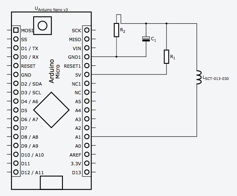
C1 is 100uF
R1+2 are 15k
-
SCT-013-030 Energy MeterOk I tested it and it works fine. Because the reading of low current was not acurate I change readings up to 60W as 0W. I mesure the energy consumption of a room dryer that consumes about 1400W. Mabe SCT-013-005 would be more acurate in low current mesurements.