Skip to content
  • MySensors
  • OpenHardware.io
  • Categories
  • Recent
  • Tags
  • Popular
Skins
  • Light
  • Brite
  • Cerulean
  • Cosmo
  • Flatly
  • Journal
  • Litera
  • Lumen
  • Lux
  • Materia
  • Minty
  • Morph
  • Pulse
  • Sandstone
  • Simplex
  • Sketchy
  • Spacelab
  • United
  • Yeti
  • Zephyr
  • Dark
  • Cyborg
  • Darkly
  • Quartz
  • Slate
  • Solar
  • Superhero
  • Vapor

  • Default (No Skin)
  • No Skin
Collapse
Brand Logo
S

Samuel235

@Samuel235
Hardware Contributor
About
Posts
815
Topics
40
Shares
0
Groups
1
Followers
2
Following
3

Posts

Recent Best Controversial

  • In wall light switch node - Custom PCB
    S Samuel235

    So here we have it guys, Revision 2 is now complete, tested and working perfectly! Its been a grueling process but so rewarding. I plan on making a few tiny little changes, including some headers/jumpers to allow ISP uploads while the radio is attached and pull-up resistors to the switch lines. I will get these all ironed out in the next few days and get the designs sent off to get the final boards manufactured. However, I don't feel that there is a great rush for this last board as the upgrades are very minor ones that won't effect its usability right now. The files on the original post are all up to date and relevant including the schematic. I'm yet to test the current draw, I'm trusting that it is sleeping in between the switch toggles, would this be tested via the current draw, if so where should it be measured to confirm this?

    Here are a few photographs of the final board attached to a switch plate:

    2_1457169881232_IMG_7361.JPG
    1_1457169881232_IMG_7360.JPG
    0_1457169881222_IMG_7359.JPG

    Hardware custompcb inwall node light switch switch

  • Your workshop :)
    S Samuel235

    And in full swing of prototyping, as promissed:
    0_1462609864319_image.jpg

    General Discussion

  • In wall light switch node - Custom PCB
    S Samuel235

    With a little open-heart surgery, the board becomes alive! While I'm yet to actually burn any bootloader to the uC itself, I have no got the circuitry working.

    The known issues:

    • Capacitor on the SPI Header was incorrectly connected. I had wired it like a resistor/diode.
    • The VCC line from the SPI was connected to the uC through the resistor of the RESET circuit.
    • Battery holder is connected in reverse.

    I have attached images for anyone interested in following this project with actual pictures of the progression through the revisions of this node. I have now made some alterations in my documentations regarding Rev1, listed the known issues and made some possible improvements:

    • Remove one 47uF capacitor.
    • Move the 47uF capacitor closer to battery terminal, and have all power traces coming through that capacitor, reducing the chance of the battery being drained through large spikes in draw.
    • Add capacitor to FTDI VCC to stop spikes when connecting programming board.
    • Increase silkscreen labels for document data such as pinouts and node info.
    • Remove the 100uF capacitor on the nRF24l01+, add a 4.7uF footprint and 0.1uF footprint. Only populate if needed.
    • Turn around the switch terminals, room should allow this.
    • Bring the 0.1uF capacitors closer to the VCC inputs on the uC.

    This week I will be aiming to get the designs and re-routes for Rev2 sorted out, and then get them ordered, with express shipping this time hopefully. The 3 weeks of waiting killed me!

    Please give your feedback, if you have any.

    IMG_7132.jpg IMG_7133.jpg IMG_7139.jpg IMG_7134.jpg

    Hardware custompcb inwall node light switch switch

  • Your workshop :)
    S Samuel235

    This is mine in the clean state, a decent working size but its not a dedicated area, it has to server as my office too. I'm looking to extend the desk round to the left under the window and have a dedicated electronics area. I will upload a image of the desk in action in the near future.

    Some little Ni-Cad cells in the right storage hole as you can see, this is the only electronic piece out at the moment :(

    0_1459702399445_image.jpg

    General Discussion

  • In wall light switch node - Custom PCB
    S Samuel235

    BINGO!!

    We have a working coin cell powered light switch.
    2_1455483349684_image.jpeg 1_1455483349683_image.jpeg 0_1455483349682_image.jpeg

    I will upload some decent images later on tonight or tomorrow.

    I'de just like to talk everyone that has contributed to this thread/post and enabled me to create my first of many embedded projects. I'm applying for a University course in september for Computer Science (Smart Technologies), all about embedded systems, drones, home automation etc etc. This is just the beginning!

    I'll get this project up on OpenHardware.io asap as Version 1 and we can build on this as a base plate for futher projects.

    Hardware custompcb inwall node light switch switch

  • Your workshop :)
    S Samuel235

    The first of many new tools to reside on my desk/bench!

    0_1459860094224_image.jpg

    General Discussion

  • Homini Complete Room Sensor Module?
    S Samuel235

    And the first of many to arrive is the Figaro Carbon Monoxide sensor.

    0_1461139111942_image.jpeg

    Hardware ceiling motion sensors gas sensor light sensor homini humidity ceiling mount smoke detector temperature module complete room light

  • Your workshop :)
    S Samuel235

    I think we should get a tooling topic going, what major testing equipment we all have and what we wish to gather in the future (if any) and then recommended tooling for new comers to purchase to help get their hobby off to a good start. Yes, I'm in that later category.

    I will get one made within the next week if no one does it before me. Too busy right now unfortunately, so would appreciate if someone else did it but if they don't I will see to it asap!

    General Discussion

  • Operational Amplifiers - Differential Amplifiers
    S Samuel235

    Here is the schematic for the sensor:

    0_1463234709893_SensorSchematic.jpg

    Hardware op amp operational amplifier differential amplifier

  • Clearance, creepage and other safety aspects in "MySensors" PCBs.
    S Samuel235

    @sundberg84 - Thank you for spending your time to iron out all the information floating around the internet currently regarding this topic, to some it seems very overwhelming when researching to design a module, myself included struggle with this topic. Your time spent will help others save time and effort, again, thank you!

    Hardware pcb ac power creepage clearance acdc

  • Self Powered Inline AC Double Relay Module
    S Samuel235

    The current sensors have areived so i've thrown the high voltage section together on the board and about to 'idle' test the device.

    First test will be a 1 hour period of no attached devices and no low voltage circuitry in place. Purely testing the high voltage side.

    0_1469202575591_image.jpg
    0_1469202610096_image.jpg

    Hardware lighting relay ac power

  • Current Sensing?
    S Samuel235

    @scalz - Thank you for providing that link. I've now just realise how easy this module could potentially be. I also don't like the idea of it costing nearly £20 for that sensor that sticks onto the LED. If we want a dumb node option, this sensor on the front relaying back to MySensors like the example sketch does right now, but i'm thinking a sensor like that small round module that sticks onto the meter, connected to the arduino (possibly through a 3.5mm jack to make it simple for remove and install) and then a custom made atmega board in a box sending off the data to MySensors.

    I think i may have my next project already! I may make this nRF24l01 and RFM69 compatible rather than just the nRF24l01 that i use. We could get this stuck on the front with some simple velcro tape cut in the same shape as the light sensor module to be neat, a little 3D printed case with another custom made board holding the light sensor circuitry inside.

    I'm going to draft up some ideas for this and publish here for you guys to see.

    Hardware

  • 💬 MySensors Contest 2017
    S Samuel235

    Awwwww yeahhhh! Here we go, lets see more hardware being designed, manufactured, tested and shared around us. Community driven is best!

    Announcements

  • 💬 4-channel switcher/dimmer
    S Samuel235

    @HouseIOT - From my understanding of a varistor: it stops voltage spikes and voltage spikes are the things that causes arcs and therefore shorts on the board. I would include one, i do on my modules anyway.

    OpenHardware.io contest2017 mysensors dimmer

  • In wall light switch node - Custom PCB
    S Samuel235

    Hello.

    My first contribution to MySensors is going to be a Light Switch node that meets a few lines of criteria. To my knowledge, this hasn't been developed yet and feel that there would be a fair few people that would benefit from a very simple switch node that actually fits in a location where an existing switch does, that way there is no signs of home automation on the switch front. Yes we have scene controllers that can be mounted onto the wall, but this starts to become bulky and obvious that there is some sort of technology there controlling something, what about if you simply just want to switch a light on with natural instincts without having to look at what you're doing? This is where I personally think this Product would prove itself worthwhile. There are currently two other projects like this going on here at the MySensors forum:
    @sundberg84's In Wall PCB - This is a node using two PCB's stacked together that will sit inside of Swedish style wall appliance box and have its own power fed to it.
    @martinhjelmare's: Box for In Wall PCB - This is a box that simply sits inside of the socket to contain all the open high voltages of electricity if being reduced down from 240v on the PCB itself.

    If there is any electricians roaming around here, please, advise me of any serious, specific implications, rules and regulations that this would need to meet that i haven't stated so. I will be getting some mock schematic and PCB designs sorted out for you guys to look at for a starting point. I will make it very obvious now that I'm not a profession electronics guy, nor am i someone that has experience in designing PCB's, electronic designs or anything. This is a huge learning curve for me, but as a community i do believe we can put together some awesome products, alongside of @sundberg84 and @martinhjelmare's proposed outcomes.

    Product Criteria:

    1. Fits inside of a slimline (25mm depth) UK Wall metal AND plastic back box/dry lining box.
    2. Able to be powered via Battery and/or mains electricity, either 240v straight from the power circuit or have it transformed down to the 5v in a central location/outside of the socket box then fed into the box for application.
    3. Allowing you to keep existing wires in the box, but terminated. This would allow us backward capabilities of reverting our alterations in case of selling the property.
    4. Form factor/Footprint must be a small as possible to remove any possible issues on the space allocated.

    The Product itself:
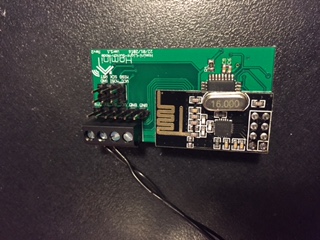
    The product itself will be based around an Arduino Mini Pro powered via either a cell coin battery, AA batteries or a mains electric feed reduced down to the required voltage, I'm thinking 5v step down outside of the box (in a central location, maybe even in the electric room (where your main breaker is located) then stepped down from 5v to 3.3v on the board itself. The whole system will be created and located onto a custom PCB that i propose to be all SMD, to allow for a smaller form factor for the already challenging installation size. This product will start out to be a simple ON/OFF switch, a dimming version will be the first upgrade offered to the product. The product will include a nRF24L01 radio transceiver to deal with its networking, so that is going to need some revision for the metal back box version to allow the transceiver to work with the metal, if it has issues that is.

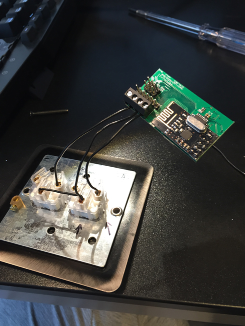
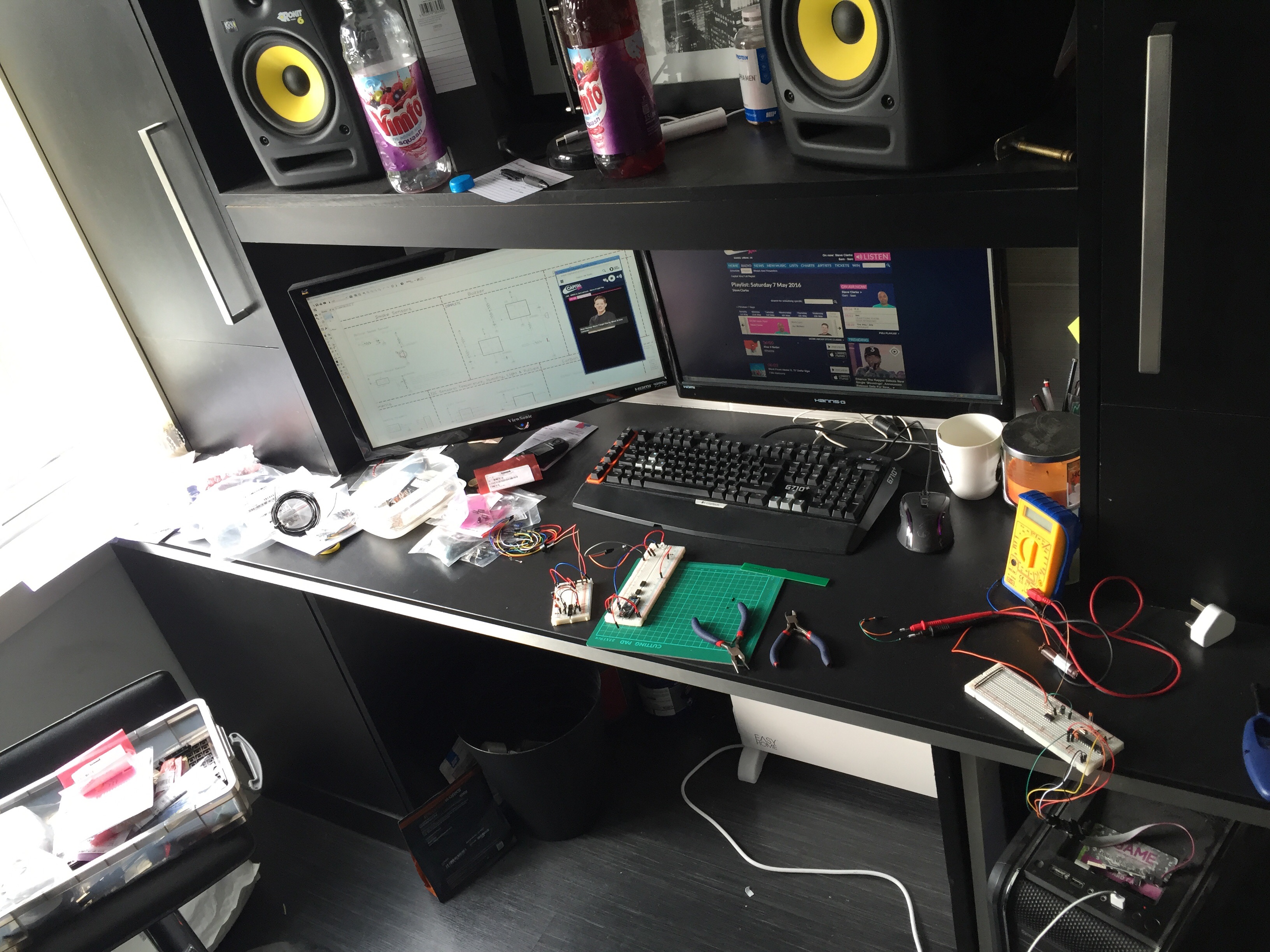
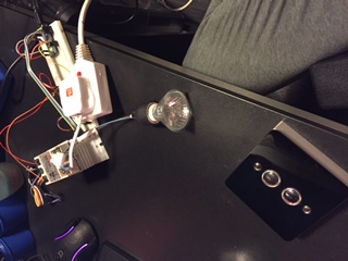
    Currently, I have a breadboard setup with an Arduino Nano, a light switch faceplate doing the switching and an nRF24L01 doing the transmitting back to my MQTT gateway. So currently outside of the Arduino, all that is needed is terminals for the switch itself and a resistor for the switch. Then we will need the power solution, so a coin cell holder, resistors, caps whatever is needed to feed a stable 3.3v to the micro controller. The mains connection, this is going to need screw terminals, and again caps, resistors and whatever else is needed to reduce down the power (I'm still thinking to bring the mains in at 5v, so step them down outside of the application). If anyone feels like pointing me in the right direction in terms of whats needed to bring mains power down, feel free. I will continue to research the correct ways to do such a thing in the meantime.

    Environment Design work:
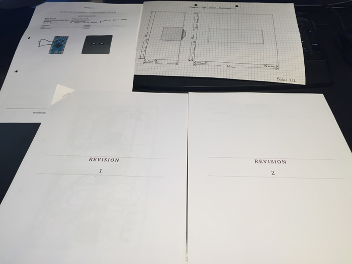
    I have made a pretty accurate design in google sketchup as a starting environment for the first installation of this product detailing sizes that we have to work with to enable us to fit this inside of the existing wall back box.

    Light Switch.png

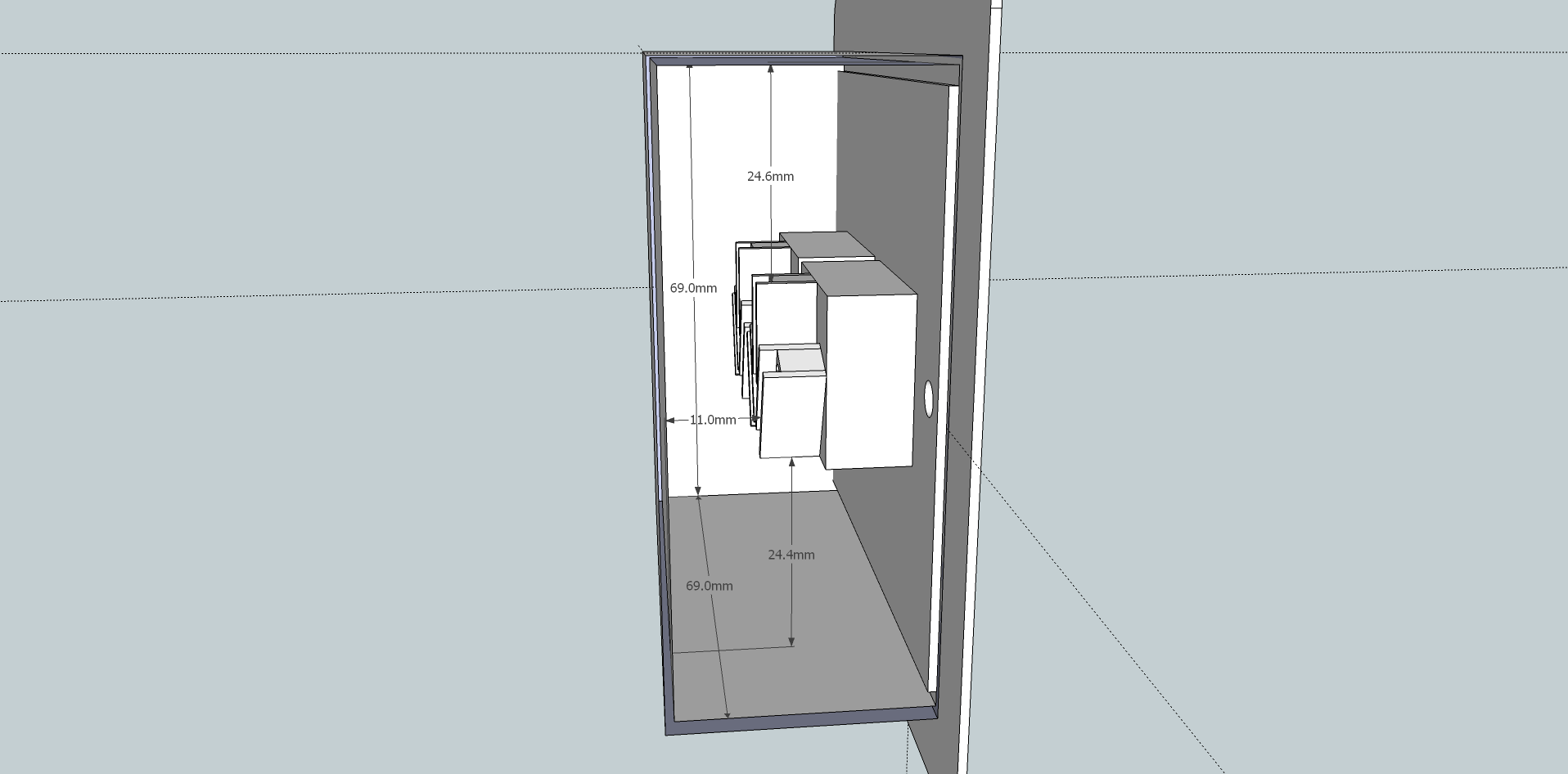
    The Environment for the Product:
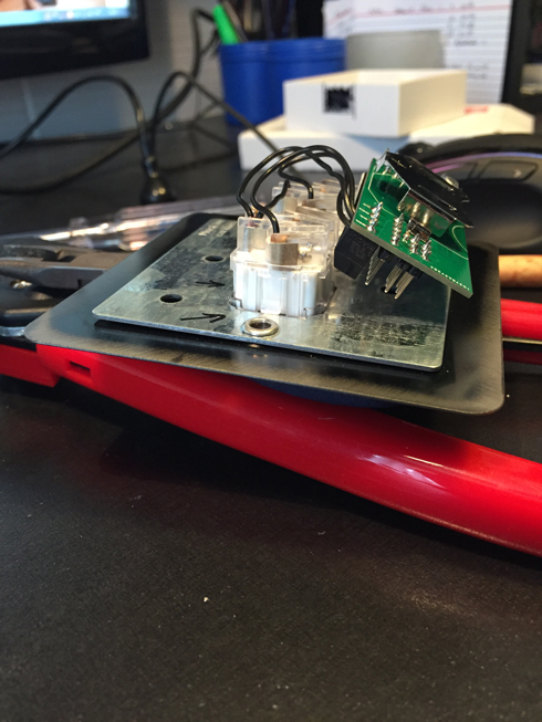
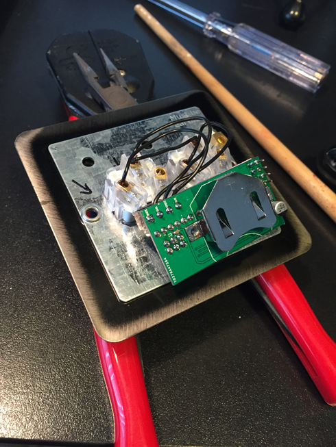
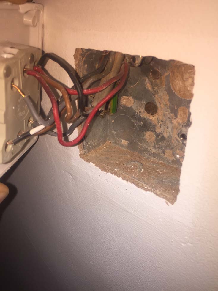
    For example, the below images show a light switch placement that i currently have, hopefully this will give some indication the room that we have to work with here to allow the existing cables to be terminated and left where they are for future needs. A normal back box or dry lining box installed now would be 35mm to sometimes even 50mm boxes, however we must allow for such situations that arise where the plasterers (Like myself) have had no choice but to install a 25mm box.

    DISCLAIMER: I did not install the current switch, which as you can see is a pretty poor installation to say the least. I will be using an electrician to do any mains electrical work, and therefor I'm not going to allow anything below the national standard to be installed into my property.
    IMG_6882.JPG

    DISCLAIMER: I do not advise you in any way to make/install this product into a property and therefore I take no responsibility for any issues, problems you have or even health implications that you endure while completing the installation or even using the product after installing.

    UPDATES

    24th December 2015 - Version 1.1 Revision 1 boards have been ordered and currently being produced with ITead.cc.
    24th December 2015 - Parts have been ordered for the production of 1 evaluation node.
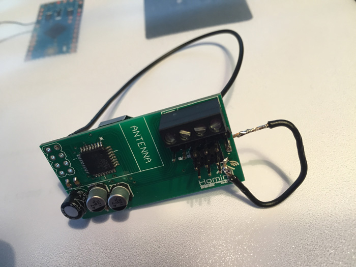
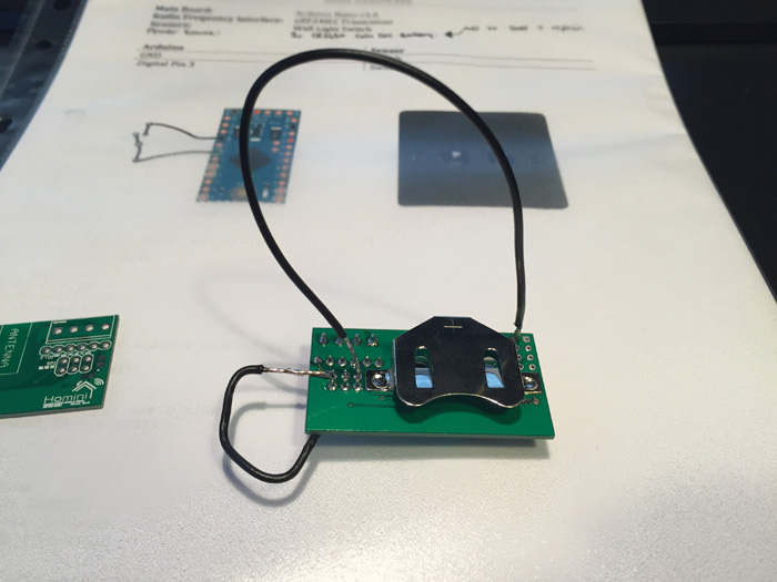
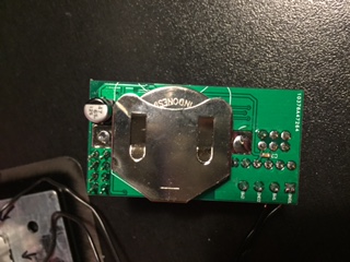
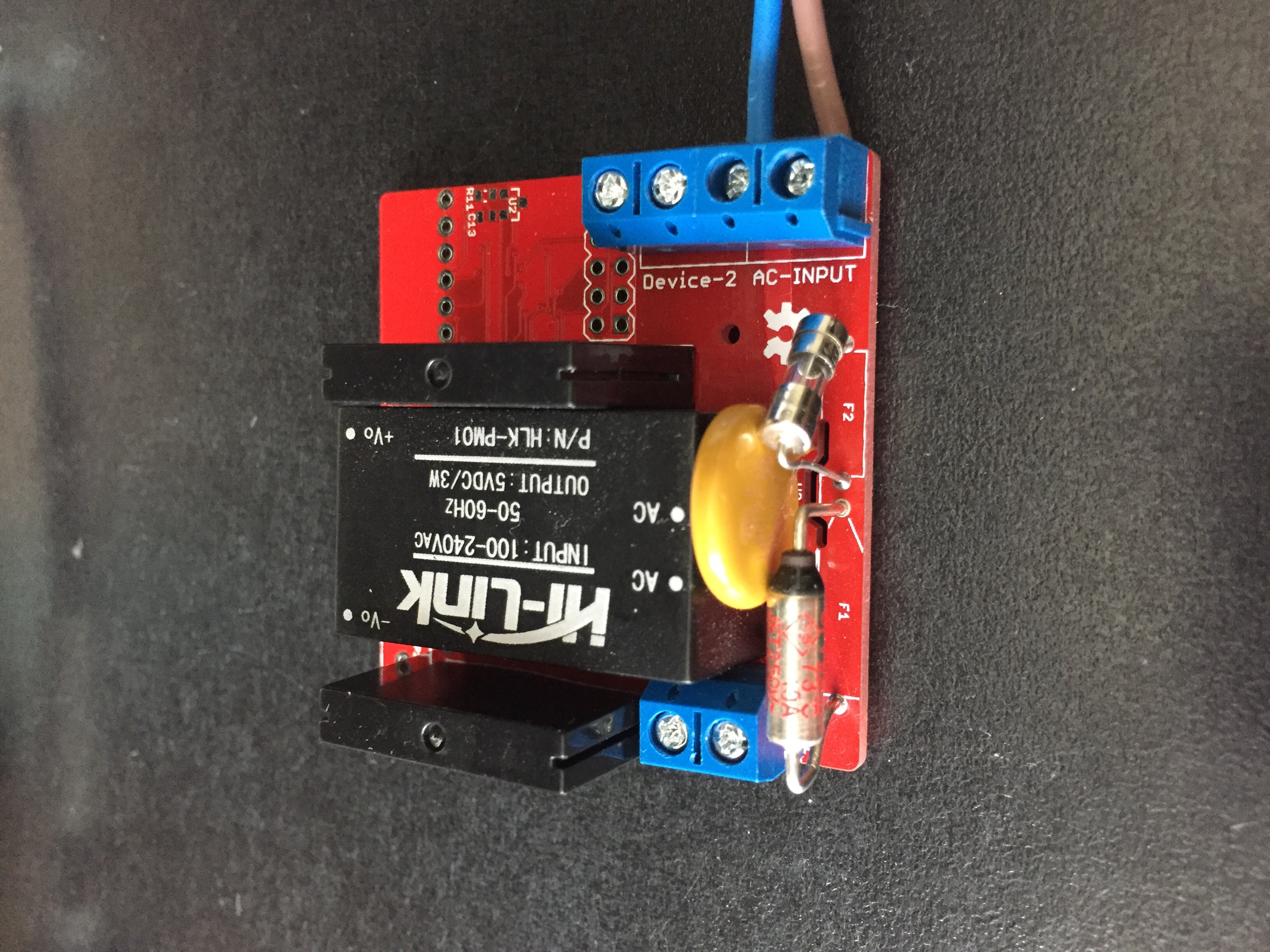
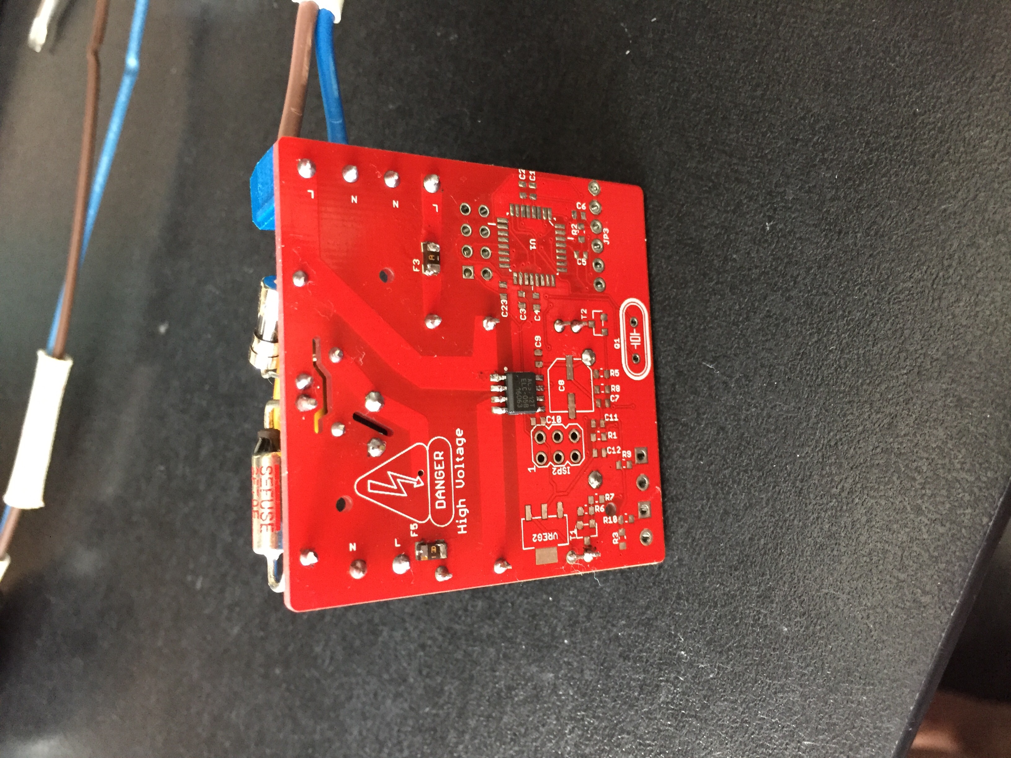
    14th January 2016 - Version 1.1 Revision 1 board has arrived, populated with components.
    23rd January 2016 - Version 1.1 Revision 2 boards have been ordered and currently being produced with ITead.cc.
    13th February 2016 - Version 1.1 Revision 2 boards have been received and populated.
    19th February 2016 - Version 1.1 Revision 2 boards are currently going through their first 24-Hour long testing period.
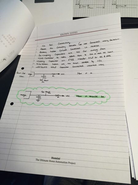
    21st February 2016 - Version 1.1 Revision 2 boards are undergoing troubleshooting work.
    5th March 2016 - Version 1.1 Revision 2 boards are completed and power usage tests are currently taking place.
    19th March 2016 - Version 1.1 Revision 2 has been uploaded to https://www.openhardware.io/view/48/Homini-In-Wall-Battery-Powered-Light-Switch-Module

    FILES
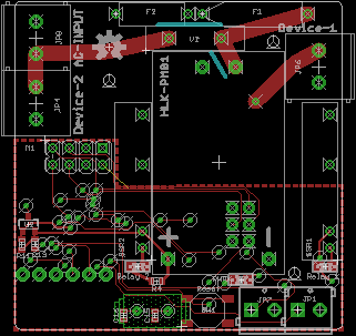
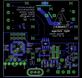
    Current Eagle Files - Homini_Light_Switch_Node_Version_1.1_Revision_2.zip
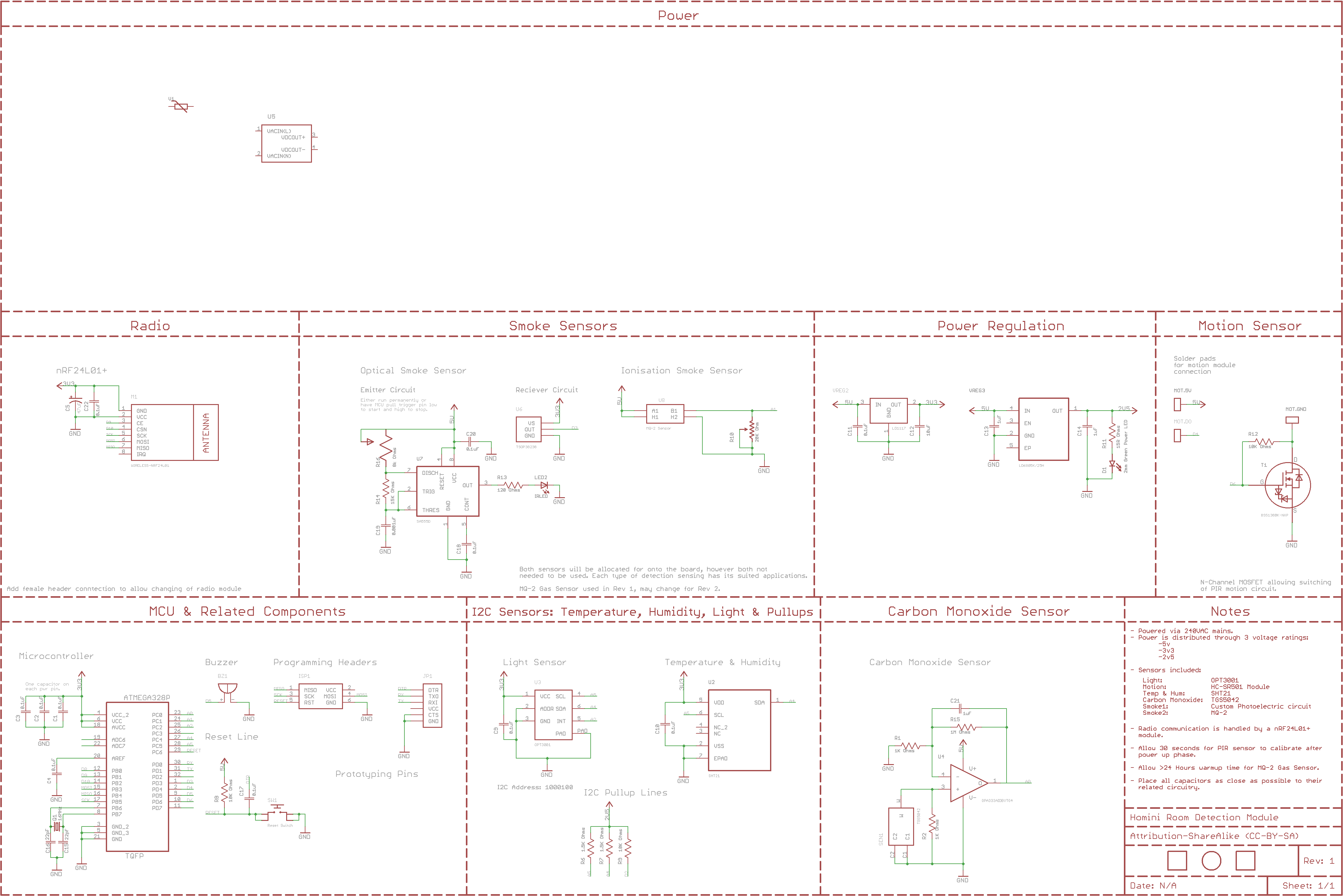
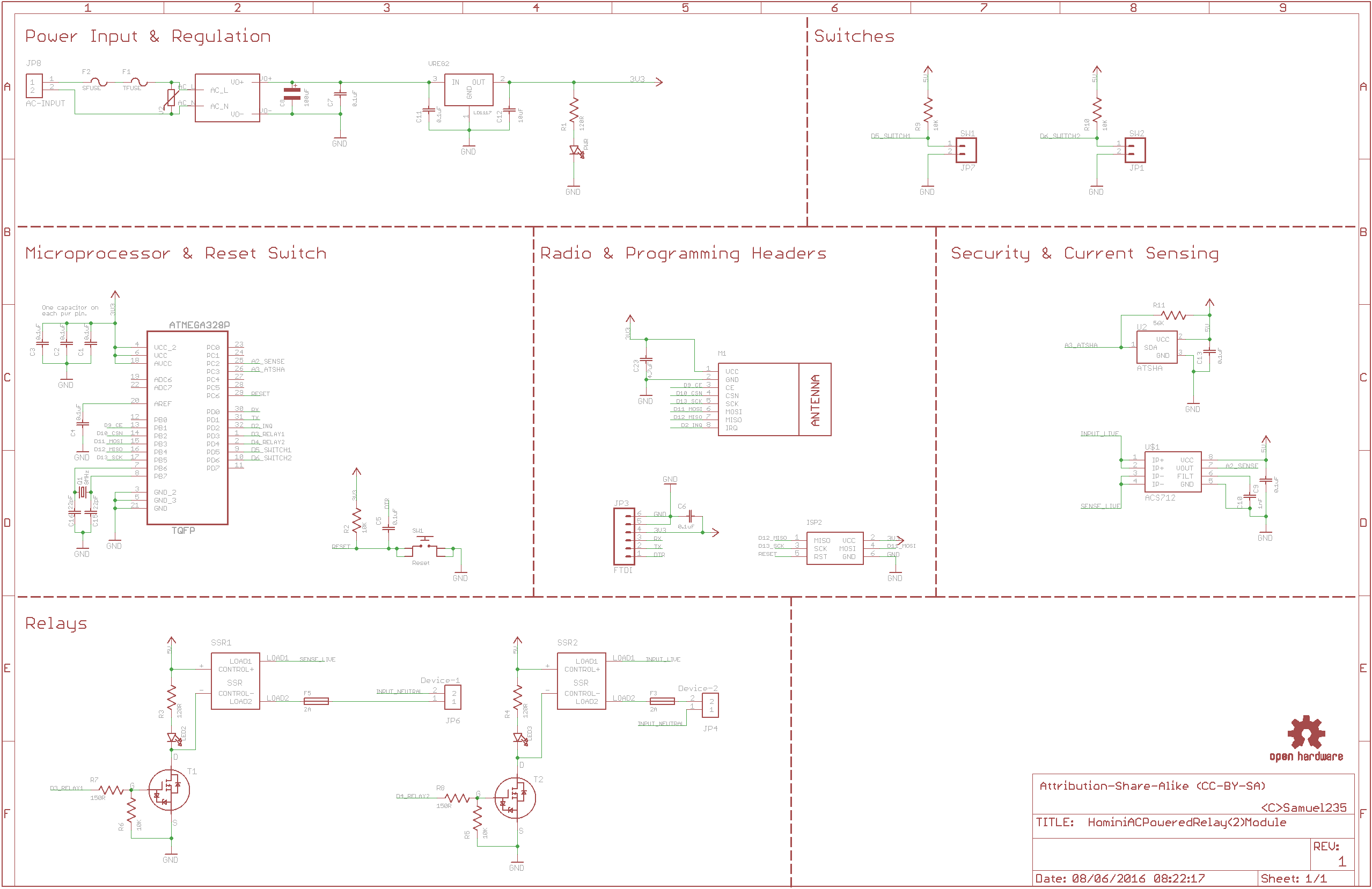
    Schematic PDF - 1_1457169973710_HominiSwitchNode1.0Rev2_Sch.pdf
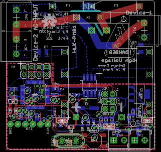
    Board PDF - 0_1457169973709_HominiSwitchNode1.0Rev2_Brd.pdf
    Gerber Files - 0_1457460927449_Rev2 Gerbers.zip
    BOM - 0_1457593789223_HominiSwitchNode1.0Rev2BOM.csv

    Hardware custompcb inwall node light switch switch

  • 💬 Homini Pulse Meter Monitor
    S Samuel235
    • Mains powered version of the sensor works as planned.
    • Controller works on mains power and battery power.

    Awaiting my LDRs, soon as they arrive I will get the battery version tested and will mark this build as complete. I will also make the device available for sale as a complete kit from myself. Will include links on openhardware.io soon as this becomes available.

    In the kit you will receive:
    1 x Battery or mains version of the sensor including enclosure and cable.
    1 x Controller board (nRF24l01 version) including enclosure.

    All kits are available to purchase completely ready to use OR as component kits for you to solder yourself (to save some cost). Not sure on pricing yet, will release that at the time of product release.

    I will only supply the nRF24L01 version at the moment as that is all that i have capability of testing.

    All questions are welcome in the mean time, and all suggestions for future upgrades are considered.

    OpenHardware.io contest2017 power power monitor homini mysensors power consumption pulse pulse sensor

  • In wall - PCB, (AC to DC 5v)
    S Samuel235

    @sundberg84 This is awesome progress dude!

    So in my honest opinion, from a professional tradesman plastering, tiling, stud walls, plaster boarding are my specialties, I would firstly test this inside of a back-box, outside of a wall with the front attached (like it would be in a real-life situation). Then once that passes your expectations and requirements, I would then test it inside of a back-box located inside of a wall but without the front plate screwed on. Then once that passes, I would connect the front plate and manually monitor the temps inside of the controller.

    If your question was aimed more towards how to test it electronically, then i'm sorry i can't help in that department, as you already know, I'm pretty weak at electronics at the moment still.

    Its awesome to see your project coming on, very swiftly too. Keep up the good work!

    Hardware pcb inwall

  • New ATMega328PB
    S Samuel235

    Good morning guys, just a little bit of 'news', off topic here though.

    Every morning I make my oatmeal and sitdown for 20 minutes in front of my computer either reading news, electronics or watching a youtube video. This morning I came across some Atmel news on Hackaday, ATMEL ATmega328PB. Not sure how old the news is, whether or not you have already seen it but I just thought I would post it here to let people know if they haven't found out about the new model already :)

    Hardware

  • Homini Complete Room Sensor Module?
    S Samuel235

    UPDATE

    So then guys. I feel I have the sensing side of the board all designed out, I will include a schematic here for you to see. Just due to my inexperience of electronics still, i'm sure there will be a few faults/things you guys would like me to change around. Please point anything of any concern out to my attention and i will amend accordingly.

    Sensors

    Light: OPT3001
    Motion: HC-SR501 Module
    Temperature & Humidity: SHT21
    Carbon Monoxide: TGS5042
    Smoke1: Custom Photoelectric Circuit
    Smoke2: MQ-2.

    The smoke sensors can both be fitted or one or the other. They will differ in applications, what area the module is being used in. They both detect different types of smoke/fires. I will included more detailed information on this for the release of the product.

    Powering

    I'm still yet to design the powering side of this, it will be 240VAC converted to 5VDC then regulated as and when needed. I Will include some way to externally power this module while we're programming it since it will draw more than i'm comfortable providing through a PC USB Socket. So there will be no VCC lines coming onto the board from the USB programmers, this way we can't cause any damage to your PC USB sockets/serial lines. I'm yet to work out the overall typical power consumption, which i do plan on calculating today so i can get the powering converters specified for the current needed.

    Prototyping

    If there is any pins left, currently have 5 pins (3 Analog and 2 Digital) left over, however i'm very tempted to have status LEDs on this module so therefor that will be 3 gone and will only leave possibly 2 empty analog pins. These will have VIAs located so we can use them for prototyping.

    By no means is this schematic anywhere near completion, there may be floating connections or missing components. Please point them out if so.
    Excuse the unfinished power circuit at the top of the schematic, this is where i've got to so far before i ran out of time. Currently just placed the varistor and the AC/DC Converter. Will keep updating as and when time allows.

    0_1460927870597_HominiRoomDetectionSchematic.png

    Hardware ceiling motion sensors gas sensor light sensor homini humidity ceiling mount smoke detector temperature module complete room light

  • Self Powered Inline AC Double Relay Module
    S Samuel235

    Self Powered Inline AC Double Relay Module

    I've come up with the designs for a double relay module for AC power that can monitor/sense the current of the module and its attached relays. The primary use for these would be as lighting controllers/relays, being all powered from the same AC input, this should allow to be installed on the lighting circuit that you wish to control and allow for one more circuit to be controlled/isolated. Being the size that it is (50mm square) we are able to fit this into the ceiling or wall, away from sight and allow for 2 manual switches to be wired directly onto the module itself or allowing the use for another type of switch, even that of the wireless light switch module i have previously created here.

    Module Requirements

    • Be small as possible.
    • Be as safe as possible.
    • Allow for use in sheltered outdoor applications.
    • Sense and monitor its current usage.
    • Have 2 external switch terminals, manual switching may be needed.
    • Have Atsha204 signing for security in outdoor applications.

    So after many nights of researching, designing and brainstorming I have completed the first drafts of designs for this module. The module includes; Slow blow fuse, AC transformer to generate 5V DC power on-board, 2 x 2A fuses for the relays to allow safety on-board rather than on the electricity main ring, Atsha204A signing, ACS712 current sensor and nRF24L01+ radio (Which is located in such a way that you can switch this out for the more powerful version if needed).

    The module will fit on a 50mm x 50mm board to allow for cheaper production and smaller, more compact encasing. Most traces for the DC side of the board are all done in 6mm, I may increase the power lines slightly, if space allows. Vias are all done in a 0.3mm drill size, again i may attempt to increase these slightly if space allows. The below image of the board layout shows how untidy the routing is, it took me a while to get it all connected up and will be looking to tidy up my signal lines before production commences.

    Upload Methods

    The upload methods that i have included are FTDI and ISP. However, to gain advantage of either of these you will need to use POGO PINS or an alternative as there is no room for the physical header pins at the moment.

    Images

    Schematic:
    0_1465371277411_HominiACPowered(2)RelayModule.png

    Board View:
    0_1465371264542_HominiACPoweredRelay(2)ModuleBRD.png

    Board-Top View:
    0_1465371257816_HominiACPoweredRelay(2)ModuleBRDTOP.png

    Board-Bottom View:
    0_1465371251759_HominiACPoweredRelay(2)ModuleBRDBOT.png

    Files

    HominiACPoweredRelay(2)Module.zip

    All suggestions are more than welcome, they are encouraged actually.

    Hardware lighting relay ac power
  • Login

  • Don't have an account? Register

  • Login or register to search.
  • First post
    Last post
0
  • MySensors
  • OpenHardware.io
  • Categories
  • Recent
  • Tags
  • Popular