Navigation

    • Register
    • Login
    • OpenHardware.io
    • Categories
    • Recent
    • Tags
    • Popular
    1. Home
    2. sundberg84
    3. Posts
    • Profile
    • Following
    • Followers
    • Topics
    • Posts
    • Best
    • Groups

    Posts made by sundberg84

    • RE: NewbiePCB sensors dying of old age

      Hi @Matt - yea, i experience the same, my nodes with the Chinese voltage boosters/converters seems to be dying and my guess has been noice from those components. Im converting more and more over to 5v power from wallsockets and stuff and I also found the 433mhz radios more reliable than the NRF radios still... but I'm really happy, I still have some nodes up that is probably around 10 years now - way longer than I expected 🙂 I mean, that's sometimes better than bought nodes 😉

      Agree with you that learning new stuff is the best with this kind of projects - I have also used the smaller slim nodes and they have some applications. But Im actually moving the other way, to bigger nodes - with modular components. I have to resolder and program everything again so if possible when a node fails I can easily change the component. For example, my gateways now uses "shields" that I can just plug and play on a Uno with easy changeable radio.

      posted in General Discussion
      sundberg84
      sundberg84
    • RE: 💬 HLK-PM01 breakout board

      @titou4307 Hello! I dont really work on that project anymore, but its open hardware and all files are there so feel free to modify

      posted in OpenHardware.io
      sundberg84
      sundberg84
    • RE: 💬 Easy/Newbie PCB (RFM69 HW/W edition) for MySensors

      @hlehoux - nice once! Thanks for sharing!

      posted in OpenHardware.io
      sundberg84
      sundberg84
    • RE: 💬 HLK-PM01 breakout board

      @RobIII - there is no specific reason why I choose 73dgr, probably it was easy avalible.
      70-85 woudl sure work good.

      posted in OpenHardware.io
      sundberg84
      sundberg84
    • RE: 2021 EU customs regulatory changes — where should I buy now?

      @benhub - this has been an issue for a long time in Sweden now.
      "Postnord" adds 7,5€ as handeling fee and then VAT ontop on everything.

      European sellers is one option, but in some cases shopping from ebay they claim to be in Europe but the package comes from Asia adress. Some Asian sellers has now made an agreement with Postnord to include VAT which solves the issue with 7,5€ handeling fee, but still not as cheap as before.

      posted in General Discussion
      sundberg84
      sundberg84
    • RE: 💬 Easy/Newbie PCB for MySensors

      @benhub - ok, there are some things you need to consider, and that is the space of the adapter.
      I read now i "suggested" this adapter, but let me clear it it is not tested, maybe a language barrier from my side.

      You need to consider that it fits in the board and do not crash into other compontens, like the arduino.
      If it does, you maybe need to consider some other board or even build one.

      posted in OpenHardware.io
      sundberg84
      sundberg84
    • RE: 💬 Easy/Newbie PCB for MySensors

      @benhub - hello!
      You need some sort of adapter, the use similar pins but not in the same order/layout.
      Here is a suggestion for adapter: https://www.openhardware.io/view/601/NRF24-to-RFM69-converter

      But... you know there is a RFM version of the EasyPCB right?
      https://www.openhardware.io/view/389/EasyNewbie-PCB-RFM69-HWW-edition-for-MySensors

      posted in OpenHardware.io
      sundberg84
      sundberg84
    • RE: 💬 Capacitive Soil Moisture Sensor

      Nice work @Ron . Thinking about getting some of these for my plants.
      Any experienced issues, or the PCB and components works good?

      posted in OpenHardware.io
      sundberg84
      sundberg84
    • RE: What did you build today (Pictures) ?

      @KooLru - very clever sollution for the lines.

      posted in General Discussion
      sundberg84
      sundberg84
    • RE: Anything needed to do before sending Message after a long sleep ?

      @hlehoux the purpose of the booster is to boost the voltage up to 3.3v for the Pro Mini. If you have a battery with voltage range 3,7 - 4V this isnt needed and may just cause the issues you are having.

      Instead you need to lower the voltage to 3.3v depending on the pro mini version you use.
      In the EasyPCB examples there are some guides you can look at.

      posted in Development
      sundberg84
      sundberg84
    • RE: Anything needed to do before sending Message after a long sleep ?

      @hlehoux - it looks like you use a booster?
      Why are you using this with 3,7 - 4V battery?

      9972e6ac-cdf1-4fe0-9ba3-aa0bff3d5c04-image.png

      In most cases, issues like this are related to booster performance.
      If you need the booster, can you try to change it out?

      posted in Development
      sundberg84
      sundberg84
    • RE: Clearance, creepage and other safety aspects in "MySensors" PCBs.

      @JohanH - thanks for your reply! I also hope and think people who build commercial products have knowledge of this 🙂
      But as a hobbyist, there are two ways to go - either you dont have to care or go bare minimum, if something happens its your own fault, or you can try to make is as safe as possible.

      My idea was never to make this thread a information source for a commercial product. I wanted to try to make my own products as safe as possible since I have children around. With that in mind, i want to be on the safe side of things so some things i use from here might be exaggerated.

      But my PCB (HLK-PM01 breakout) is working great, and I feel safe. I have had it outdoors (under roof covered in IP5* box, -20 to +30 aprox) and its been working for me for a couple of years now. Better than I had before, when i just stripped an old fake samsung charger.

      /Andreas

      posted in Hardware
      sundberg84
      sundberg84
    • RE: CR2032 coin cells - expected life?

      @NeverDie - I measure after - but I let the battery recover from the transmission, so you have a valid point.
      @BearWithBeard - Thanks - if you can do it, I can 🙂
      @ncollins - a big capasitor sounds lika a good idea, 1.8v bod I have and also sleep (5 minutes). Thanks for the input, sounds like a plan ahead.

      posted in Hardware
      sundberg84
      sundberg84
    • CR2032 coin cells - expected life?

      Hi! Im having issues when testing MySensors nodes with CR2032.

      9c2633af-f75f-4e53-b802-f4a1ee54297e-image.png

      BOD are set to 2.3 but it seems like the node dies around 2,8-2,9 and it does not last very long.
      Its a "naked" testnode, nrf24, sleep active, minial current drain.

      First, is it to be expected that these batteries does not work below 2.8v?
      Any other tips?

      posted in Hardware
      sundberg84
      sundberg84
    • RE: Automated Pergola

      Cool! Now you need to use a MySensors rain sensor, and/or wind/sun/temp sensors to automate the closing and opening of all the things automaticly!

      posted in My Project
      sundberg84
      sundberg84
    • RE: Handling NACKs

      @evb - yes, that is correct, here is a complete sketch with a GW (Nrf24 - ethernet)

      // Enable debug prints to serial monitor
      #define MY_DEBUG
      
      // Enable and select radio type attached
      #define MY_RADIO_NRF24
      #define MY_RF24_PA_LEVEL RF24_PA_MAX
      
      // Enable gateway ethernet module type
      #define MY_GATEWAY_W5100
      
      // Enable Soft SPI for NRF radio (note different radio wiring is required)
      // The W5100 ethernet module seems to have a hard time co-operate with
      // radio on the same spi bus.
      #if !defined(MY_W5100_SPI_EN) && !defined(ARDUINO_ARCH_SAMD)
      #define MY_SOFTSPI
      #define MY_SOFT_SPI_SCK_PIN 14
      #define MY_SOFT_SPI_MISO_PIN 16
      #define MY_SOFT_SPI_MOSI_PIN 15
      #endif
      
      // When W5100 is connected we have to move CE/CSN pins for NRF radio
      #ifndef MY_RF24_CE_PIN
      #define MY_RF24_CE_PIN 5
      #endif
      #ifndef MY_RF24_CS_PIN
      #define MY_RF24_CS_PIN 6
      #endif
      
      #define MY_IP_ADDRESS 192,168,1,8   // If this is disabled, DHCP is used to retrieve address
      // Renewal period if using DHCP
      //#define MY_IP_RENEWAL_INTERVAL 60000
      // The port to keep open on node server mode / or port to contact in client mode
      #define MY_PORT 5003
      
      // Controller ip address. Enables client mode (default is "server" mode).
      // Also enable this if MY_USE_UDP is used and you want sensor data sent somewhere.
      //#define MY_CONTROLLER_IP_ADDRESS 192, 168, 178, 254
      
      // The MAC address can be anything you want but should be unique on your network.
      // Newer boards have a MAC address printed on the underside of the PCB, which you can (optionally) use.
      // Note that most of the Ardunio examples use  "DEAD BEEF FEED" for the MAC address.
      #define MY_MAC_ADDRESS 0xDE, 0xAD, 0xBE, 0xEF, 0x01, 0x08 //AF-A0-F2-15-3B-1C
      
      // Set blinking period
      #define MY_DEFAULT_LED_BLINK_PERIOD 300
      
      // Enable inclusion mode
      //#define MY_INCLUSION_MODE_FEATURE
      // Enable Inclusion mode button on gateway
      //#define MY_INCLUSION_BUTTON_FEATURE
      // Set inclusion mode duration (in seconds)
      //#define MY_INCLUSION_MODE_DURATION 60
      // Digital pin used for inclusion mode button
      //#define MY_INCLUSION_MODE_BUTTON_PIN  3
      
      // Uncomment to override default HW configurations
      #define MY_DEFAULT_ERR_LED_PIN 7  // Error led pin
      #define MY_DEFAULT_RX_LED_PIN  9  // Receive led pin
      #define MY_DEFAULT_TX_LED_PIN  8  // the PCB, on board LED
      
      
      #define MY_INDICATION_HANDLER
      static uint32_t txOK = 0;
      static uint32_t txERR = 0;
      #define REPORT_INTERVAL 300000 // Report every 5 minutes
      #define CHILD_ID_TX_OK 0
      #define CHILD_ID_TX_ERR 1
      
      #include <SPI.h>
      
      #if defined(MY_USE_UDP)
      #include <EthernetUdp.h>
      #endif
      #include <Ethernet.h>
      #include <MySensors.h>
      
      MyMessage txOKmsg(CHILD_ID_TX_OK, V_CUSTOM);
      MyMessage txERRmsg(CHILD_ID_TX_ERR, V_CUSTOM);
      
      void indication(indication_t ind)
      {
        switch (ind)
        {
          case INDICATION_TX:
            txOK++;
            break;
          case INDICATION_ERR_TX:
            txERR++;
            break;
        }
      }
      
      void presentation()
      {
        //Send the sensor node sketch version information to the gateway
        sendSketchInfo("Gateway #1", "1.0");
        present(CHILD_ID_TX_OK, S_CUSTOM);
        present(CHILD_ID_TX_ERR, S_CUSTOM);
      }
      
      void setup()
      {
      }
      
      void loop() {
      
        static unsigned long last_send = 0;
        if (millis() - last_send > REPORT_INTERVAL) {
          send(txOKmsg.set(txOK));
          send(txERRmsg.set(txERR));
          last_send = millis();
        }
      
      }


      In Home Assistant you need to create a sensor that breaks down the incrementing number to each intervall you want.
      I use a utility_meter.

      utility_meter:
      hourly_ok_gw:
          source: sensor.gateway_1_0_0
          cycle: hourly
        hourly_err_gw:
          source: sensor.gateway_1_0_1
          cycle: hourly
      

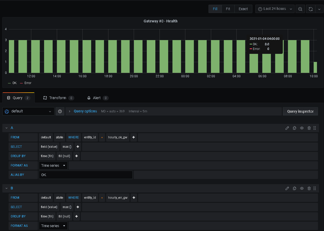
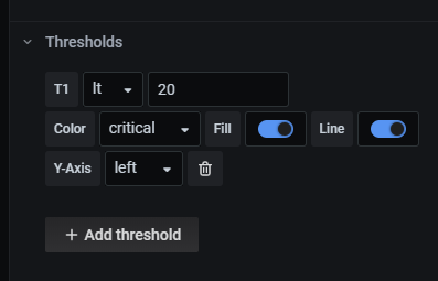
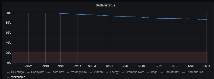
      This sensors will be sent to Grafana each hour just like any other sensor and you can create a graph there:

      2556f0fa-a34b-49da-bac6-e0a8aadbd633-image.png

      posted in Development
      sundberg84
      sundberg84
    • RE: 💬 MySensors Nrf24/RFM Serial/Ethernet GW Shield (for Uno)

      @hlehoux My quickfix means you cant use the ethernet shield.
      All I did was solder with wires to the normal pins and made it a serial gateway.

      posted in OpenHardware.io
      sundberg84
      sundberg84
    • RE: 💬 Easy/Newbie PCB (RFM69 HW/W edition) for MySensors

      @evb - correct!

      6e3f6c73-744d-427f-b7d8-c07619c4bc9f-image.png

      b42bbc87-8030-44e7-a9e1-511112500872-image.png

      posted in OpenHardware.io
      sundberg84
      sundberg84
    • RE: 💬 Easy/Newbie PCB (RFM69 HW/W edition) for MySensors

      @evb - Hi, to be hones I don't even remember. I dont have any exact equipment to measure except a normal multimeter, so that can be that my reading is way off, or it was without the radio? Sorry, no documentation about this and no memory at this point. But here is the battery of my EasyPCB RFM + Dallas temp sensor. I changed the batteries 3 months ago as you see and currently is about 87%.

      fce2a441-b446-48d0-b041-fd4043e74409-image.png

      posted in OpenHardware.io
      sundberg84
      sundberg84
    • RE: Best radio type for 5 floor communication

      @andrezibaia - my understanding that lower frequencies easier penetrate walls, and im also suspecting the Nrf24l01+ (2.4Ghz) wont work. Im using RFM69 for my outdoor nodes, and its working well penetrating the house walls - but in your case you have multiple floors (thicker than walls?)... If you have the radios, I would try them.

      posted in Hardware
      sundberg84
      sundberg84
    • RE: What did you build today (Pictures) ?

      Current issue: outdoor nodes random stops/disappears - maybe during the time when its high humidity, so trying to try some different approaches i read - this multisensor is getting painted with clear nail polish. Also this PCB is a new board im testing, that Im hoping to be the base for my "final" home automation nodes. Still in dev. but great possibilities!

      75f113be-7ad8-4f12-a9f0-2e237aa57004-image.png

      posted in General Discussion
      sundberg84
      sundberg84
    • RE: What did you build today (Pictures) ?

      IMG_20201026_090317.jpg

      Today im testing and outdoor node in a new PCB, but I had mixed csk and ce on the radio (it's a dual radio PCB).

      posted in General Discussion
      sundberg84
      sundberg84
    • RE: 💬 Connecting the Radio

      Connection diagram/circuit between RFM module and atmega328p-au TQFP footprint.

      534dda4f-7899-44b6-b852-3b3fbeff6f2a-image.png

      posted in Announcements
      sundberg84
      sundberg84
    • RE: What did you build today (Pictures) ?

      @tssk - really like your design! Well done.

      posted in General Discussion
      sundberg84
      sundberg84
    • RE: Big metal barn radio interference???

      @nzbaxterman - I had the same issue with a power meter inside a metal box. I drilled a small hole trough the box, put the radio on dupont cables and outside the box and voila, worked great.

      posted in Troubleshooting
      sundberg84
      sundberg84
    • RE: 💬 MyGateway

      @Gerator - Nice project! How did you solve dual SPI channels for ethernet and RFM radio?

      Ethernet gateway using Arduino UNO with Ethernet shield stacked JP1 should be 1-2 and JP2 2-3.

      posted in OpenHardware.io
      sundberg84
      sundberg84
    • RE: Gateway W5100 with RFM69 fails to compile

      @Dirk_H - this is exactly the same for me. Are you using logic level converters?

      posted in Troubleshooting
      sundberg84
      sundberg84
    • RE: 💬 PulseTAC

      Nice project!

      posted in OpenHardware.io
      sundberg84
      sundberg84
    • RE: Gateway W5100 with RFM69 fails to compile

      @Dirk_H - I have the same issue, but I do not get softSPI to work on a Uno + Ethernet Module + RFM69. Can you confirm that softSPI works for you and Ethernet Module? What pins do you use for softSPI (analog?)

      posted in Troubleshooting
      sundberg84
      sundberg84
    • RE: 💬 MySensors Nrf24/RFM Serial/Ethernet GW Shield (for Uno)

      Anyone good with SPI channel analysis?

      Hardware SPI (Looks great):
      3de4dd2e-0577-48d3-9d1c-10742605ee74-image.png

      Software SPI (Same setup, just changed code and pins).
      a5279a91-af78-4d0f-966d-622c03c377aa-image.png

      In the first, I can clearly see MOSI and MISO communicating on 5/6. Enable on 7.
      Software SPI does not make any sense.

      posted in OpenHardware.io
      sundberg84
      sundberg84
    • RE: 💬 MySensors Nrf24/RFM Serial/Ethernet GW Shield (for Uno)

      What im noticing is that when I connect the radio, the IRQ line on D2 is 1.0v when high and not 3.3v. Anyone who knows this is normal behaviour? Same with two different (and comfirmed working) radios. SPI logic level converter is comfirmed working and changed with same behavoir.

      Edit > This is the same using normal pins and does not have anything to do with SPI. It works when not using softSPI and IRQ has this low voltage...

      posted in OpenHardware.io
      sundberg84
      sundberg84
    • RE: New ethernet gateway errors out on Home Assistant

      @mrhutchinsonmn - i dont know if this can help you but this is my homeassistant configuration with ethernet gateway:

      mysensors:
        gateways:
          - device: '192.168.X.X'
            persistence_file: 'mysensors/mysensors.json'
            tcp_port: 5003 
        optimistic: false
        persistence: true
        version: '2.3'
      

      and here is my ethernet gateway:

      // Enable debug prints to serial monitor
      #define MY_DEBUG
      
      // Enable and select radio type attached
      #define MY_RADIO_NRF24
      #define MY_RF24_PA_LEVEL RF24_PA_MAX
      
      // Enable gateway ethernet module type
      #define MY_GATEWAY_W5100
      
      // Enable Soft SPI for NRF radio (note different radio wiring is required)
      // The W5100 ethernet module seems to have a hard time co-operate with
      // radio on the same spi bus.
      #if !defined(MY_W5100_SPI_EN) && !defined(ARDUINO_ARCH_SAMD)
      #define MY_SOFTSPI
      #define MY_SOFT_SPI_SCK_PIN 14
      #define MY_SOFT_SPI_MISO_PIN 16
      #define MY_SOFT_SPI_MOSI_PIN 15
      #endif
      
      // When W5100 is connected we have to move CE/CSN pins for NRF radio
      #ifndef MY_RF24_CE_PIN
      #define MY_RF24_CE_PIN 5
      #endif
      #ifndef MY_RF24_CS_PIN
      #define MY_RF24_CS_PIN 6
      #endif
      
      #define MY_IP_ADDRESS 192,168,1,8   // If this is disabled, DHCP is used to retrieve address
      // Renewal period if using DHCP
      //#define MY_IP_RENEWAL_INTERVAL 60000
      // The port to keep open on node server mode / or port to contact in client mode
      #define MY_PORT 5003
      
      // Controller ip address. Enables client mode (default is "server" mode).
      // Also enable this if MY_USE_UDP is used and you want sensor data sent somewhere.
      //#define MY_CONTROLLER_IP_ADDRESS 192, 168, 178, 254
      
      // The MAC address can be anything you want but should be unique on your network.
      // Newer boards have a MAC address printed on the underside of the PCB, which you can (optionally) use.
      // Note that most of the Ardunio examples use  "DEAD BEEF FEED" for the MAC address.
      #define MY_MAC_ADDRESS 0xDE, 0xAD, 0xBE, 0xEF, 0x01, 0x08 //AF-A0-F2-15-3B-1C
      
      // Set blinking period
      #define MY_DEFAULT_LED_BLINK_PERIOD 300
      
      #include <SPI.h>
      
      #if defined(MY_USE_UDP)
      #include <EthernetUdp.h>
      #endif
      #include <Ethernet.h>
      #include <MySensors.h>
      
      void presentation(){
      }
      
      void setup(){
      }
      
      void loop() {
      }
      
      posted in Home Assistant
      sundberg84
      sundberg84
    • RE: 💬 MySensors Nrf24/RFM Serial/Ethernet GW Shield (for Uno)

      I have now tested all SPI lines and its logic level converter individually.
      To be absolutely sure the hardware worked, I desoldered the radio and wrote a arduino program sending 5v in 5 sek over the same sofwareSPI lines and 0V over 5 sek - all behaved correctly, 3.3v and 0V.

      I also swapped radio, but same same...

      Not really sure how to proceed. I need to get the softwareSPI working or else I cant use it as a ethernet gateway.

      Is there someone here that got RFM gateway working with softwareSPI?
      I dont think its the hardware anymore...
      Code:

      #include <SPI.h>
      
      // Enable debug prints to serial monitor
      #define MY_DEBUG
      
      // Enable and select radio type attached
      
      #define MY_RADIO_RFM69
      #define MY_RFM69_NEW_DRIVER
      #define MY_RFM69_FREQUENCY RFM69_433MHZ // Set your frequency here
      //#define MY_IS_RFM69HW
      
      #define MY_SOFTSPI
      #define MY_SOFT_SPI_SCK_PIN 14
      #define MY_SOFT_SPI_MISO_PIN 16
      #define MY_SOFT_SPI_MOSI_PIN 15
      
      #define MY_RFM69_CS_PIN 6
      #define MY_RFM69_IRQ_PIN 2
      
      #define MY_SIGNING_ATSHA204
      #define MY_SIGNING_ATSHA204_PIN A3
      #define MY_SIGNING_REQUEST_SIGNATURES
      #define MY_SIGNING_WEAK_SECURITY 
      
      // Enable serial gateway
      #define MY_GATEWAY_SERIAL
      
      #include <MySensors.h>
      
      void setup()
      {
          // Setup locally attached sensors
      }
      
      void presentation()
      {
          // Present locally attached sensors
      }
      
      void loop()
      {
          // Send locally attached sensor data here
      }
      
      posted in OpenHardware.io
      sundberg84
      sundberg84
    • RE: 💬 MySensors Nrf24/RFM Serial/Ethernet GW Shield (for Uno)

      @Nick-Willis - great to hear.
      By using dupont cables and "normal pinout" for RFM radio i now also get the new driver to work thanks to your input.

      #include <SPI.h>
      
      // Enable debug prints to serial monitor
      #define MY_DEBUG
      
      // Enable and select radio type attached
      
      #define MY_RADIO_RFM69
      #define MY_RFM69_NEW_DRIVER
      #define MY_RFM69_FREQUENCY RFM69_433MHZ // Set your frequency here
      #define MY_IS_RFM69HW
      
      //#define MY_SOFTSPI
      //#define MY_SOFT_SPI_SCK_PIN A0
      //#define MY_SOFT_SPI_MOSI_PIN A1
      //#define MY_SOFT_SPI_MISO_PIN A2
      
      //#ifndef MY_RF24_CE_PIN
      //#define MY_RF24_CE_PIN 5
      //#endif
      //#ifndef MY_RF24_CS_PIN
      //#define MY_RF24_CS_PIN 6
      //#endif
      
      #define MY_SIGNING_ATSHA204
      #define MY_SIGNING_ATSHA204_PIN A3
      #define MY_SIGNING_REQUEST_SIGNATURES
      #define MY_SIGNING_WEAK_SECURITY 
      
      // Enable serial gateway
      #define MY_GATEWAY_SERIAL
      
      #include <MySensors.h>
      
      void setup()
      {
          // Setup locally attached sensors
      }
      
      void presentation()
      {
          // Present locally attached sensors
      }
      
      void loop()
      {
          // Send locally attached sensor data here
      }
      
      ⸮S[0;255;3;0;9;0 MCO:BGN:INIT GW,CP=RPNGAA--,FQ=16,REL=255,VER=2.3.2
      0;255;3;0;9;108 TSM:INIT
      0;255;3;0;9;111 TSF:WUR:MS=0
      0;255;3;0;9;114 TSM:INIT:TSP OK
      0;255;3;0;9;116 TSM:INIT:GW MODE
      0;255;3;0;9;119 TSM:READY:ID=0,PAR=0,DIS=0
      0;255;3;0;9;123 MCO:REG:NOT NEEDED
      0;255;3;0;14;Gateway startup complete.
      0;255;0;0;18;2.3.2
      0;255;3;0;9;128 MCO:BGN:STP
      0;255;3;0;9;135 MCO:BGN:INIT OK,TSP=1
      0;255;3;0;9;138 TSM:READY:NWD REQ
      0;255;3;0;9;145 ?TSF:MSG:SEND,0-0-255-255,s=255,c=3,t=20,pt=0,l=0,sg=0,ft=0,st=OK:
      

      IMG_20200730_172146.jpg

      But with SofSPI engaged - not working-

      0;255;3;0;9;0 MCO:BGN:INIT GW,CP=RPNGAA--,FQ=16,REL=255,VER=2.3.2
      0;255;3;0;9;0 MCO:BGN:INIT GW,CP=RPNGAA--,FQ=16,REL=255,VER=2.3.2
      0;255;3;0;9;277 TSM:INIT
      0;255;3;0;9;279 TSF:WUR:MS=0
      0;255;3;0;9;282 !TSM:INIT:TSP FAIL
      0;255;3;0;9;285 TSM:FAIL:CNT=1
      0;255;3;0;9;288 TSM:FAIL:DIS
      0;255;3;0;9;290 TSF:TDI:TSL
      
      • Continuity on all logic level converters are OK
      • Not much traffic at all from the UNO in SPI. I guess the intial contact with the radio is faulty so thats why.

      It must be either connection Uno > Logic Level Shifter > Radio, code / defines or softwareSPI not working.

      posted in OpenHardware.io
      sundberg84
      sundberg84
    • RE: 💬 MySensors Nrf24/RFM Serial/Ethernet GW Shield (for Uno)

      You are correct, it should look like this:
      b1a9bc0b-987e-4592-b470-e546a9fa744b-image.png I will update this to the final version. Can you comfirm you have 3.3v on the RFM module?

      I will try with both #defines - that might work! Thanks for that.

      One thing to do (quickfix) if you want to use it as a serial gateway is to cut the pinheaders for all SPI channels. Then hardswire the SPI channels to the normal pins 10-13 instead of softSPI which is currently using. You ofcourse needs to solder them from the pinheader and not RFM module itself since you need to logic level conversion. I will give this a new go as soon as I have time. I really really want a RFM gateway over ethernet.

      posted in OpenHardware.io
      sundberg84
      sundberg84
    • RE: 💬 MySensors Nrf24/RFM Serial/Ethernet GW Shield (for Uno)

      So, today I have been making some test for RFM radio + this shield.
      With the new driver, it seems ok - but I suspect TSP=NA isnt a good sign.
      This happens both with SoftSPI with and without the shield attached.

      0;255;3;0;9;0 MCO:BGN:INIT GW,CP=R-NGAA--,FQ=16,REL=255,VER=2.3.2
      0;255;3;0;14;Gateway startup complete.
      0;255;0;0;17;2.3.2
      0;255;3;0;9;359 MCO:BGN:STP
      0;255;3;0;9;365 MCO:REG:NOT NEEDED
      0;255;3;0;9;368 MCO:BGN:INIT OK,TSP=NA
      

      With a logic analyser, I cant seen any activity at all from the UNO on the defined softSPI pins. All I see here is some activity on RX and some on A3 (for signing - atsha chip)

      2e727f86-6834-40ef-b481-14f94c187e5f-image.png

      By removing softSPI from the code, using default pins (and bridge the uno to my shield with dupont cables) i get exactly the same as above, TSP=NA

      Could it be that SoftSPI uses analog pins, and im using logic level converters on the shield...

      By just replacing the new driver with //#define MY_RADIO_RFM69 i get a more correct looking log:

      0;255;3;0;9;0 MCO:BGN:INIT GW,CP=RRNGAA--,FQ=16,REL=255,VER=2.3.2
      0;255;3;0;9;108 TSM:INIT
      0;255;3;0;9;111 TSF:WUR:MS=0
      0;255;3;0;9;114 TSM:INIT:TSP OK
      0;255;3;0;9;117 TSM:INIT:GW MODE
      0;255;3;0;9;120 TSM:READY:ID=0,PAR=0,DIS=0
      0;255;3;0;9;123 MCO:REG:NOT NEEDED
      0;255;3;0;14;Gateway startup complete.
      0;255;0;0;18;2.3.2
      0;255;3;0;9;129 MCO:BGN:STP
      0;255;3;0;9;135 MCO:BGN:INIT OK,TSP=1
      0;255;3;0;9;139 TSM:READY:NWD REQ
      0;255;3;0;9;145 ?TSF:MSG:SEND,0-0-255-255,s=255,c=3,t=20,pt=0,l=0,sg=0,ft=0,st=OK:
      

      I can also see things happening all over all SPI logic channels.

      So whats up with the new driver? Did i not define it right?

      // Enable and select radio type attached
      #define MY_RFM69_NEW_DRIVER
      #define MY_RFM69_FREQUENCY RFM69_433MHZ // Set your frequency here
      

      Or is it using other than default pins?

      posted in OpenHardware.io
      sundberg84
      sundberg84
    • RE: 💬 MySensors Nrf24/RFM Serial/Ethernet GW Shield (for Uno)

      @Nick-Willis - I have not had the time yet to investigate this. It is not the same serial output as you (and im not using an ethernet shield for my RFM gateway). It seems in your serial output that the radio cant be initialised at all (no contact).

      Thi is my code:

      include <SPI.h>
      
      // Enable debug prints to serial monitor
      #define MY_DEBUG
      
      // Enable and select radio type attached
      #define MY_RFM69_NEW_DRIVER
      #define MY_RFM69_FREQUENCY RFM69_433MHZ // Set your frequency here
      
      #define MY_SOFTSPI
      #define MY_SOFT_SPI_SCK_PIN 14
      #define MY_SOFT_SPI_MOSI_PIN 15
      #define MY_SOFT_SPI_MISO_PIN 16
      
      #ifndef MY_RF24_CE_PIN
      #define MY_RF24_CE_PIN 5
      #endif
      #ifndef MY_RF24_CS_PIN
      #define MY_RF24_CS_PIN 6
      #endif
      
      // Enable serial gateway
      #define MY_GATEWAY_SERIAL
      
      #include <MySensors.h>
      
      void setup()
      {
          // Setup locally attached sensors
      }
      
      void presentation()
      {
          // Present locally attached sensors
      }
      
      void loop()
      {
          // Send locally attached sensor data here
      }
      
      posted in OpenHardware.io
      sundberg84
      sundberg84
    • RE: Delivery from PCBWay?

      @P72endragon - I ordered from PCBway as well, a long time ago - just received today they got to Sweden. I should say it takes longer that usual (6weeks) when you got the confirmation they are sent.

      posted in Hardware
      sundberg84
      sundberg84
    • RE: 💬 MySensors Nrf24/RFM Serial/Ethernet GW Shield (for Uno)

      @Nick-Willis - yes I did, and when I used the new driver everything compiled and the node started, but I got a strange serial log message saying radio = 0 (not radio failed) or something.

      posted in OpenHardware.io
      sundberg84
      sundberg84
    • RE: 💬 MySensors Nrf24/RFM Serial/Ethernet GW Shield (for Uno)

      @Nick-Willis @Nick-Willis - Im also trying out the RFM version, but not finished yet. I need to run the signals through a signal analyser, Either i messed some soldering up or something else i up with this... Im getting that MySensors does not recognize the radio, but I have to use softspi and not sure yet how this works with MySensors and Rfm.
      R1-R3 (led current limiting resistor = 330 - 1k
      R4 - R13 = 10k pullups
      C1 = 0,1uF, C2 = 10uF C3= Nrf24l01+ resistor, 4.7µ - 47µF

      posted in OpenHardware.io
      sundberg84
      sundberg84
    • RE: Easy PCB Question

      @TRS-80 - who needs to be here wathing your hardware questions when you have such a good community - thanks 🙂 @grumpazoid - thanks for your kind words.
      I read through it all - it seems all questions was answered? EasyPCB isnt designed for 662K but as said, if you look at the pinout on the board compare it to EasyPCB pinout you will be able to figure out if you can rotate and/or bend the leads and solder it somehow. But... its not designed for that regulator so its going to be some... diy 😉

      Pinout LE33 (EasyPCB design).
      07154b9e-e1ab-430b-9005-a1bc652a534a-image.png

      Pinout

      f2bb367f-62aa-4c88-9595-20c7efec7ca3-image.png

      If i read this right, you accually have to put this upside down if tou want to use this footprint and its going to be... not the most easy soldering job.

      posted in Hardware
      sundberg84
      sundberg84
    • RE: Nodemanage + EasyPCB Sleep

      @ElCheekytico correct, every pin you have on the mysx connector.

      posted in NodeManager
      sundberg84
      sundberg84
    • RE: What did you build today (Pictures) ?

      Interupted by our first "Summer" lightning, but in replacing my old Rfm69 gateway (old one works, but uses a ftdi adapter for Serial communication and i have another need for the adapter). In the same time im taking up signing. The node has a atsha chip but I never used it properly which im going to try to fix.

      IMG_20200523_162944.jpg

      posted in General Discussion
      sundberg84
      sundberg84
    • RE: Nodemanage + EasyPCB Sleep

      @bikerMark, not sure - 10A is quite the current, i think you need some sort of relay for this. Not sure - be sure to be careful and check the datasheets .

      posted in NodeManager
      sundberg84
      sundberg84
    • RE: Nodemanage + EasyPCB Sleep

      @ElCheekytico - even better with transistor if you know how, atleast for the higher current things

      posted in NodeManager
      sundberg84
      sundberg84
    • RE: Nodemanage + EasyPCB Sleep

      @ElCheekytico sorry - I do not know the software and how this works, but if you power a display and other sensors through VCC it will still consume power. One option (if the do not use to high current) is to power them through a digital pin and set this pin to high or low before sleep to make them shut down completley., Not sure if this is possible with a display since it maybe takes quite much current (???).

      posted in NodeManager
      sundberg84
      sundberg84
    • RE: Started with MySensors and about to give up (some feedback)

      Or you can do both (RFM/NRF), which is another positive thing about Mysensors. I have also noticed how dependent NRF is on other traffic. I sometimes lose some nodes during high peak wifi hours, but only the nodes that are on "the edge" of their coverage range. So - its quite easy and cheap to build another RFM gateway, dont have to throw the NRF gateway since I have alot of indoor nodes working with that one. The garden nodes and some basement nodes are running RFM protocol - and that is a big upside with MySensors in my world.

      How i see this thread is that MySensors team or any other interested and dedicated person needs to make this clearer and maybe in some newbie guide or on the main homepage start this discussion/ state this information. In this way we can avoid all these things... For example changing the chapter "Radio" in https://www.mysensors.org/about/components so it not only shows the NRF module but also other options, and also have this "common issues" stated.

      posted in General Discussion
      sundberg84
      sundberg84
    • RE: NRF24+ Module: Spontaneous 5A heating mode?

      @The-Grue - sounds like some sort if hardware issue. I think you can rule out software. Maybe an image if the faulty hardware?

      This is the first time I hear about this to be honest - unless there has been for example solder shorts but since its working after changing the radio it seems like an issue with the radio.

      posted in Troubleshooting
      sundberg84
      sundberg84
    • RE: TV on/off monitor using TV USB port

      @tomvanderputte - some service port announces events on the data lines. You could use this to (if they are present) to determine if the tv is on or off and send a binary sensor. The issue with the ping approach is the amount of traffic, in balance with some lag in the update on your sensor. I guess you dont want to ping the tv every second and therefore it might be some time before your controller sense your power goes off - and this might cause issue if you want to use the sensor in any automation.

      posted in Hardware
      sundberg84
      sundberg84
    • RE: 💬 Battery Powered Sensors

      @Sebex - i think thats the easiest way, but sometimes its fun to try to create something new - its not impossible, but I would try to reverse engineer the nano (already done - search arduino nano schematic) and there you have to identify all "not essential" components and remove those (ie, making it a big pro-mini) to be able to get the current down as much as possible.

      posted in Announcements
      sundberg84
      sundberg84
    • RE: 💬 Battery Powered Sensors

      The big chip to the left is also a serial-usb converter which needs to be removed, making it not possible to program from the usb socket. Along with these components there are resistors and other components that might blead current so i dont think its that easy compared to just doing it to a Pro Mini.

      posted in Announcements
      sundberg84
      sundberg84
    • RE: What did you build today (Pictures) ?

      @Nca78 - Well, its been around 14-17dgr C today, so almost room temp. Strange
      @Yveaux - hahaha, best answer! Saving uA!

      posted in General Discussion
      sundberg84
      sundberg84
    • RE: What did you build today (Pictures) ?

      Another picture from today:
      cd572dd2-1092-478e-bb59-6200ef28ad7a-image.png

      Just started working with coincells - CR2032 to be exact. Anyone knows why the battery % varies with the given temperature? Are those coincells very temp. dependent or I have made a misstake somewhere... ???

      posted in General Discussion
      sundberg84
      sundberg84
    • RE: Is it worth it adding a reset circuit to MySensors nodes?

      @Encrypt - i have a reset on My boards and use them.

      posted in Hardware
      sundberg84
      sundberg84
    • RE: 💬 HLK-PM01 breakout board

      @Almamater its a glas fuse with legs, so not a holder and fuse, that took to much space. Search axial lead fuse.

      Example:
      https://www.ebay.co.uk/itm/112791896665
      https://www.ebay.com/itm/174073055432

      posted in OpenHardware.io
      sundberg84
      sundberg84
    • RE: What did you build today (Pictures) ?

      Today I have a very strange problem. I have created a new outdoor sensor which is powered by a 240v-5v HLK module. Its working VERY intermittent and should send data every 5 minutes (no exceptions).

      Whats even more strange is that, when my outside node (called multi) is working, I have a battery powered node (sleep 15 min - send - sleep) that seems to go down, and the other way around (not always, but quite frequent - could be very unrelated but I have notised it a couple of times now).
      58a6f282-5b04-4bbc-90f4-6b0f0af37261-image.png

      Anyhow, Im very glad i build my logger node - works great once more. I use this so often and really recommend all with a bigger network to have some sort of mobile debugger. Most of the times I use the bluetooth module (2xAA powered) but at this point I have my node on my workbench powered by a USB adapter (orange wires). I then parasite power from the node to run the debugger and is now logging everything to a sd-card.

      503d3040-7208-4e95-a6cc-cb3128d24c17-image.png

      posted in General Discussion
      sundberg84
      sundberg84
    • RE: What did you build today (Pictures) ?

      Updated my GW with the code @mfalkvidd provided to monitor OK and NACK

      a2a53f2e-6227-451f-baf6-bc2ed2d66111-image.png

      posted in General Discussion
      sundberg84
      sundberg84
    • RE: Is soldering castellated pads on THT pads feasible?

      @Joost said in Is soldering castellated pads on THT pads feasible?:

      castellated pads

      Shouldn't there be castellated pads in the pro-mini to be able to accomplish this? There are regular mounting holes on the pro mini making it risky to try to solder it to a tht pad in my opinion.

      posted in Hardware
      sundberg84
      sundberg84
    • RE: Coronavirus (way, way, off topic)

      In Sweden it seems like Stockholm is preparing now for a big increase in sick people. So far its been very quiet where I live (except on the news of course). Schools still open and most work places open, but people are limiting their social contacts and working from home if possible. Toilet paper out of stock everywhere, but most other products are still there.

      But I live quite rural, so hard to say how its going in the big cities. We dont have any confirmed cases in my town but I guess its just a matter of time.

      posted in General Discussion
      sundberg84
      sundberg84
    • RE: What did you build today (Pictures) ?

      @NeverDie - so a ground plane like in here? Like that mod Pete did in his video but you inmplement it into the 3d case?

      3214fd69-c25b-4aa6-a2df-fdd54de776ed-image.png

      posted in General Discussion
      sundberg84
      sundberg84
    • RE: What did you build today (Pictures) ?

      Not sure about that groundplane @NeverDie - you are most probably right but I dont really understand the theory behind it but sounds really cool!

      3f1897f8-e82a-4554-92bf-ac16a9fe3045-image.png

      posted in General Discussion
      sundberg84
      sundberg84
    • RE: What did you build today (Pictures) ?

      @mfalkvidd - a great suggestion! It wont not block it completely but as you say, a little less.

      posted in General Discussion
      sundberg84
      sundberg84
    • RE: What did you build today (Pictures) ?

      Today I designed a case for EasyPCB with 2xAA holder on the back.

      e63319a9-b160-47ea-be2b-6b3353636e06-image.png
      a7bd451f-72d7-4004-88b0-64c43dd0e192-image.png

      and a case that slides just over.

      269327e4-e5b7-4e28-85d6-183862119e61-image.png

      It works with 3x5 version so for this you accually have to use the more advanced option and reflash the fuses on your pro mini to make it 3x5. The normal EasyPCB with booster is 5x5, but Im thinking of just stretching this for another version.

      posted in General Discussion
      sundberg84
      sundberg84
    • RE: First voltage measurement reading is high

      @grumpazoid - yes, sometimes it helps to introduce a small wait() before the reading.
      I have also made a array so i it always read 4 times and sending an average.

      posted in Troubleshooting
      sundberg84
      sundberg84
    • RE: Raspberry PI killing memory cards

      @iancu - had the same issue, went with an old desktop and Proxmox VM instead. Might be more expensive unless you have spare parts.

      posted in General Discussion
      sundberg84
      sundberg84
    • RE: Handling NACKs

      @mfalkvidd i didnt fins time yet to implement more. But very good for two repeaters.

      Screenshot_20200225-100340.png

      posted in Development
      sundberg84
      sundberg84
    • RE: arduino serial monitor gateway problem

      @kajoo - i think the resolution is to set the right permissions to the user running Domoticz.

      posted in Troubleshooting
      sundberg84
      sundberg84
    • RE: arduino serial monitor gateway problem

      @kajoo - if you are having issues on your raspberry it most likley that domoticz is not running as root or atleast have the access to the USB. Same issue occurs when you try to open a serial port with Arduino IDE in linux not run with the right access.

      posted in Troubleshooting
      sundberg84
      sundberg84
    • RE: HA: moisture sensor ValueError: could not convert string to float: '2.1.1'

      @mrhutchinsonmn - values in mysensors json looks very strange.

      "values": {
      "37": "3"
      }
      

      Not sure what else. did you try to stop HA and remove the node from mysensors json and preesnt it again?

      posted in Home Assistant
      sundberg84
      sundberg84
    • RE: Handling NACKs

      I just love this idea. Implemented the code on my second now, one to go.

      c33a129c-12ef-4a22-a966-d7c0dbe3847b-image.png

      posted in Development
      sundberg84
      sundberg84
    • RE: Handling NACKs

      @mfalkvidd - @BearWithBeard said it. The limitations are mostly math related. For example, you cant show a graph with current and last years values (timeshift) on the same graph due to that limitation in InfluxDB. I want to compare power usage this day to same day last year - not possible. Im looking to change to Graphite as well instead of Influx.

      Moving from Domoticz to HA was a great move for me, but not as i thought. Im using HA more or less just as an umbrella. I would say im using only the OS Hass.IO and not using Home Assistant that much. Whats good in Home Assistant is that its quite easy to integrate different protocolls like MySensors or whatever you use. But after that I dont use Home Assistant but the great possibilities to have add-ons on Hass.IO. I use Node Red for all my automations (Extremly easy compared to code!), Influx + Grafana for visual, motionEyeOs for camera secutiry and more... all you have to do is install the addon from the "store" and you are more or less ready to go. These addons im sure you can install with domoticz as well if you like the integrations with the different protocolls there.

      i think we have handeled the NACK questions so no worries for me if we go off topic, but if you rather like send me a dm.

      posted in Development
      sundberg84
      sundberg84
    • RE: Handling NACKs

      @mfalkvidd - its accually Grafana and Influx database. So HA sends values to Influx which are visually presented in Grafana. Im sure you can do this from Domoticz as well... there are some limitations in Influx db so I might change to another database in the future which suits me better.

      posted in Development
      sundberg84
      sundberg84
    • RE: Handling NACKs

      Something strange happened last hour:

      521328c2-1331-4efb-8998-956c027748f7-image.png

      But atleast now I know something is up.

      posted in Development
      sundberg84
      sundberg84
    • RE: Handling NACKs

      @mfalkvidd - INDICATION_GW_TX sounds like a good plan. This is a great tool I think for the future to evaluate and debug your network. I used S_CUSTOM and a utility meter (hourly) in HA to get the values.

      Just started up, first values in - will report back when I have more data:
      No errors so far 🙂

      Just so I understand: case INDICATION_ERR_TX: means NACK ?

      ded136f0-d906-4102-bfc6-daa433bf8763-image.png

      posted in Development
      sundberg84
      sundberg84
    • RE: Handling NACKs

      @mfalkvidd - appreciate you time here, should have taken me hours and hours!

      posted in Development
      sundberg84
      sundberg84
    • RE: Handling NACKs

      @mfalkvidd - do you have a pointer to where I can start, bear in mind Im a very bad coder so I need somewhere to start following the logic.

      posted in Development
      sundberg84
      sundberg84
    • RE: Battery: pro mini @ 1mhz vs booster

      @Yveaux - truly sorry my friend 🙂 All credits go to you!

      posted in Development
      sundberg84
      sundberg84
    • RE: Handling NACKs

      @BearWithBeard @karlheinz2000 - this is gold, thank you. I going to be a bit more annoying here 🙂

      What about doing this to a repeater?

      I have 3 main repeaters in my house. Do you know if it would be possible to catch the NACK / OK coming from all repeated messages? I guess we are talking changing in the core code?

      WOuld be awsome, to collect hourly OK and NACk and send to the controller for these three repeaters. It would indicate issues with both those three main nodes and also the network as a whole.

      posted in Development
      sundberg84
      sundberg84
    • RE: Handling NACKs

      @karlheinz2000 - interesting, like a incrementing pulsecounter? Or what kind of sensor do you present to do this? Im thinking for a batterynode.

      posted in Development
      sundberg84
      sundberg84
    • RE: Battery: pro mini @ 1mhz vs booster

      @kiesel i mean exactly what @NeverDie mentioned above (https://forum.mysensors.org/topic/10952/battery-pro-mini-1mhz-vs-booster/12?_=1582011000646). When voltage drops below 2.4v the 8mhz processor is "out of specs". I cant promise it works as it should, but just as neverdie I also have alot of nodes out of specs so unless you do crasy stuff and pulling much current it should work.

      About the noice questions, its very hard to diagnose or find unless you have a oscilloscope. What you might experience is bad reception and alot of :NACK messages.

      In most cases i reprogram the bootloader and use 8mhz internal or 1mhz interlan.

      posted in Development
      sundberg84
      sundberg84
    • RE: OTA not working in my current setup (CRC Error)

      @VonJoost - bug can be read about here: https://forum.mysensors.org/topic/2740/easy-newbie-pcb-for-mysensors/666

      Yes, SCK was not connected but as I said, this was fixed and new gerber has been published. I dont know what CRC errors are but if you had the issue with no connection and fixed it EasyPCB should work just fine. You should be able to check continuity with a multimeter.

      posted in Troubleshooting
      sundberg84
      sundberg84
    • RE: Battery: pro mini @ 1mhz vs booster

      Interesting all this - noticed you mentioned EasyPCB and something written in there, let me know if this can be clearer! Also worth mentioning here is that the booster will affect the radio with noice - my choise would be easy today, run it without booster if I can unless you can prove its way more efficient (longer life) with the booster. Downside with this is that you have to learn how to reprogram fuses and bootloader - but its worth the hassle.

      I just recieved a new batch of boosters and its 50/50 if they are good enough to not interfere with the radio. (Yes, its the cheap chinese mini boosters).

      posted in Development
      sundberg84
      sundberg84
    • RE: Handling NACKs

      @4994james - thanks James, but thats why I created a new thread, im interested in the node part. To create some sort of radio tester where you can send a message each second, get NACK or ACK and then output a signal/led when everything is fine to get some sort of coverage map of my house.

      posted in Development
      sundberg84
      sundberg84
    • RE: mysprinkler for mysensor and home assistant not working together

      I have added a sollution to V_VAR problem in both my rain and power pulse meter (check these threads). As said above, Homeassistant will not give an answer to these requests if there are no value in the mysensors json file. Either add this in the hardware code or as I did, request a couple of times to make sure you get the value if there is one. Count these requests and set a upper limit, like five or ten reuqest. Once your each this limit, send the value 0 to HA and this will be updated in the json file and start from there.

      posted in Home Assistant
      sundberg84
      sundberg84
    • RE: Handling NACKs

      @electrik - ok, so something like:

      
      void loop()     
      {   
          NACK = send(message to send);  
      if (NACK == 0) { Do stuff }
      }
      
      
      posted in Development
      sundberg84
      sundberg84
    • Handling NACKs

      Re: Handling NACKs in the gateway

      Is it possible to catch an NACK in the code? Say to make an if (NACK) { Do stuff } ??

      posted in Development
      sundberg84
      sundberg84
    • RE: OTA not working in my current setup (CRC Error)

      @VonJoost - there are a known bug in EasyPCB with external flash. Check you dont have boards with this bug. (Not even sure you are using external flash, but just what came up when i read the thread)

      posted in Troubleshooting
      sundberg84
      sundberg84
    • RE: 💬 Rain Gauge

      Hello! This is my just revised rain gauge sensor. Working with Homeassistant and needs a tipping bucket which closes and opens a reed switch when tipping in the different directions. (Pro Mini 3.3v, Battery operated (voltage divider included in code) and NRF24 radio).

      // Enable debug prints to serial monitor
      #define MY_DEBUG
      
      #define MY_RADIO_RF24
      #define MY_NODE_ID 7
      #define MY_PARENT_NODE_ID 99
      
      #include <SPI.h>
      #include <MySensors.h>
      
      #define DIGITAL_INPUT_SENSOR 3                  // The reed switch you attached.  (Only 2 and 3 generates interrupt!)
      
      #define CHILD_ID 1                              // Id of the sensor child
      #define SKETCH_NAME "Rain Gauge"                // Change to a fancy name you like
      #define SKETCH_VERSION "1.2"                    // Your version
      
      unsigned long SLEEP_TIME = 18 * 60000;          // Sleep time (in milliseconds).
      //unsigned long SLEEP_TIME = 20000;             // use this instead for debug
      
      float hwRainVolume = 0;                         // Current rainvolume calculated in hardware.
      int pulseCount = 0;                             // Pulsecount recieved from GW
      float fullCounter = 0;                           // Counts when to send counter
      float bucketSize = 0.5;                           // Bucketsize mm, needs to be 1, 0.5, 0.25, 0.2 or 0.1
      boolean pcReceived = false;                     // If we have recieved the pulscount from GW or not
      int recrequestcount = 0;                        //Counter for how many times we request pulses before we reset it.
      boolean reedState;                              // Current state the reedswitch is in
      boolean oldReedState;                           // Old state (last state) of the reedswitch
      unsigned long lastSend = 0;                     // Time we last tried to fetch counter.
      
      MyMessage volumeMsg(CHILD_ID, V_RAIN);
      MyMessage lastCounterMsg(CHILD_ID, V_VAR1);
      
      //=========================
      // BATTERY MEASURER
      // VOLTAGE DIVIDER SETUP
      // 1M, 470K divider across battery and using internal ADC ref of 1.1V
      // Sense point is bypassed with 0.1 uF cap to reduce noise at that point
      // ((1e6+470e3)/470e3)*1.1 = Vmax = 3.44 Volts
      // 3.44/1023 = Volts per bit = 0.003363075
      #define VBAT_PER_BITS 0.003363075
      #define VMIN 2.2                                  //  Vmin (radio Min Volt)=1.9V (564v)
      #define VMAX 3.1                                  //  Vmax = (2xAA bat)=3.0V (892v)
      int batteryPcnt = 0;                              // Calc value for battery %
      int batLoop = 0;                                  // Loop to help calc average
      int batArray[3];                                  // Array to store value for average calc.
      int BATTERY_SENSE_PIN = A0;                       // select the input pin for the battery sense point
      //=========================
      
      void presentation() {
      
        // Send the Sketch Version Information to the Gateway
        sendSketchInfo(SKETCH_NAME, SKETCH_VERSION);
      
        // Register this device as Rain sensor (will not show in Domoticz until first value arrives)
        present(CHILD_ID, S_RAIN);
      }
      
      
      void setup()
      {
      
        //=========================
        // BATTERY MEASURER
        //Set internal ref to internal to be able to measure bat 0-1v
        //Make sure this fits other sensors using analogRead()!
        //If you have a sensor reporting 0-5v you need to change analogReference() before reading that sensor.
      
        analogReference(INTERNAL);
        //DEFAULT: the default analog reference of 5 volts (on 5V Arduino boards) or 3.3 volts (on 3.3V Arduino boards)
        //INTERNAL: an built-in reference, equal to 1.1 volts on the ATmega168 or ATmega328 and 2.56 volts on the ATmega8 (not available on the Arduino Mega)
        //EXTERNAL: the voltage applied to the AREF pin (0 to 5V only) is used as the reference.
      
        //Battery inital calc
        Serial.print("With Battery VMax (100%) = "); Serial.print(VMAX); Serial.print("volts and Vmin (0%) = "); Serial.print(VMIN); Serial.println(" volts");
        Serial.print("Battery Percent 25%/50%/75% calculates to: "); Serial.print(((VMAX - VMIN) / 4) + VMIN); Serial.print("/"); Serial.print(((VMAX - VMIN) / 2) + VMIN); Serial.print("/"); Serial.println(VMAX - ((VMAX - VMIN) / 4));
        delay(1000);
        int sensorValue = analogRead(BATTERY_SENSE_PIN);
        delay(50);
        float Vbat  = sensorValue * VBAT_PER_BITS;
        int batteryPcnt = static_cast<int>(((Vbat - VMIN) / (VMAX - VMIN)) * 100.);
        Serial.print("Current battery are measured to (please confirm!): "); Serial.print(batteryPcnt); Serial.print(" % - Or "); Serial.print(Vbat); Serial.println(" Volts");
        //=========================
      
        delay(500); // Allow time for radio if power used as reset
      
        pinMode(DIGITAL_INPUT_SENSOR, INPUT_PULLUP);  // sets the reed sensor digital pin as input
      
        reedState = digitalRead(DIGITAL_INPUT_SENSOR); // Read what state the reedswitch is in
        oldReedState = reedState; // Set startup position for reedswitch
      
        Serial.println("Startup completed");
      }
      
      void loop()     {
      
        unsigned long currentTime = millis();
        //Read if the bucket tipped over
        reedState = digitalRead(DIGITAL_INPUT_SENSOR);
        Serial.println(reedState);
        Serial.println(oldReedState);
      
        boolean tipped = oldReedState != reedState;
      
        if (recrequestcount == 10 && !pcReceived) {
          //For some controllers, if you dont have any V_VAR1 stored node will not get an answer.
          //Try 10 times, then set V_VAR1 to 0 and update controller
          Serial.println("Set p-cnt and update controller");
          pcReceived = true;
          recrequestcount = 0;
          send(lastCounterMsg.set(pulseCount));  // Send pulse count 0 value to gw
          hwRainVolume = 0;
          send(volumeMsg.set((float)hwRainVolume, 1));
          lastSend = currentTime;
        }
      
        //See if we have the counter/pulse from Domoticz - and ask for it if we dont.
        if (!pcReceived && (currentTime - lastSend > 5000)) {
          request(CHILD_ID, V_VAR1);
      #ifdef MY_DEBUG
          Serial.println("Req p-cnt");
      #endif
          lastSend = currentTime;
          recrequestcount = recrequestcount + 1;
          return;
        }
        if (!pcReceived) {
          return;
        }
      
        //BUCKET TIPS!
        if (tipped == true) {
          Serial.println("The bucket has tipped over...");
          oldReedState = reedState;
          hwRainVolume = hwRainVolume + bucketSize;
          send(volumeMsg.set((float)hwRainVolume, 1));
          wait(500);
          fullCounter = fullCounter + bucketSize;
      
          //Count so we send the counter for every 1mm
          if (fullCounter >= 1) {
            pulseCount++;
            send(lastCounterMsg.set(pulseCount));
            wait(1000);
            fullCounter = 0;
          }
      
        }
      
        if (tipped == false) {
          //No bucket tipped over last sleep-period, check battery then...
          MeasureBattery();
        }
      
        lastSend = currentTime;
        sleep(digitalPinToInterrupt(DIGITAL_INPUT_SENSOR), CHANGE, SLEEP_TIME); //The interupt can be CHANGE or FALLING depending on how you wired the hardware.
      }
      
      
      void receive(const MyMessage &message)
      {
        if (message.getType() == V_VAR1) {
          pulseCount = message.getLong();
          Serial.print("Received last pulse count value from gw:");
          Serial.println(pulseCount);
          pcReceived = true;
        }
      }
      
      //=========================
      // BATTERY MEASURER
      void MeasureBattery() {  //The battery calculations
        delay(500);
        // Battery monitoring reading
        int sensorValue = analogRead(BATTERY_SENSE_PIN);
        delay(500);
      
        // Calculate the battery in %
        float Vbat  = sensorValue * VBAT_PER_BITS;
        int batteryPcnt = static_cast<int>(((Vbat - VMIN) / (VMAX - VMIN)) * 100.);
      #ifdef MY_DEBUG
        Serial.print("Battery percent: "); Serial.print(batteryPcnt); Serial.print(" % - "); Serial.print("Battery Voltage: "); Serial.print(Vbat); Serial.println(" Volts");
      #endif
      
        // Add it to array so we get an average of 3 (3x20min)
        batArray[batLoop] = batteryPcnt;
      
        if (batLoop > 2) {
          batteryPcnt = (batArray[0] + batArray[1] + batArray[2]);
          batteryPcnt = batteryPcnt / 3;
      
          if (batteryPcnt > 100) {
            batteryPcnt = 100;
          }
      #ifdef MY_DEBUG
          Serial.print("Battery Average (Send): "); Serial.print(batteryPcnt); Serial.println(" %");
      #endif
          sendBatteryLevel(batteryPcnt);
          batLoop = 0;
        }
        else
        {
          batLoop++;
        }
      }
      //=========================
      
      posted in Announcements
      sundberg84
      sundberg84
    • RE: battery life

      @HectorAllen - there are many examples on battery operated nodes. I have nodes running for 1.5 years measuring both temp, humidity, open/closed states, pulses and other stuff. To be able to do this you have to modify the nodes - its not possible to run a nano, 5v pro mini or uno out of the box and get a long life.

      posted in General Discussion
      sundberg84
      sundberg84
    • RE: 💬 Power Meter Pulse Sensor

      Hi! I have just revised my pulse sensor and have a few suggestions to the code. I have mentioned this before but there can be issues when requesting V_VAR1.

      In current code we request V_VAR1 one time and then goes to sleep, and if you like me have a 10 minute sleep period it can take along time to get V_VAR1 if you have a radio on the outside of your GW range.

      I would suggest adding:

      } else if (now - lastSend > 5000 && !pcReceived) {
          // No pulse count value received from controller. Try requesting it again.
          request(CHILD_ID, V_VAR1);
          recrequestcount = recrequestcount + 1;
      #ifdef MY_DEBUG
          Serial.println("Req p-cnt");
      #endif
          lastSend = now;
          return;
        }
      

      and before sleep:

      else if (!pcReceived) {
          //We dont want to sleep if !pcRecieved. Return and wait 5 sec to request a new value.
          return;
        }
      

      In HomeAssisant you also have the specific problem that if V_VAR1 isnt stored, the controller will not answer - so you can keep asking for a pulsecount forever without an reply. To avoid this the first time I have added:

      else if (recrequestcount == 5 && !pcReceived) {
          //For some controllers, if you dont have any V_VAR1 stored node will not get an answer.
          //Try 5 times, then set V_VAR1 to 0 and update controller
      #ifdef MY_DEBUG
          Serial.println("Set p-cnt and update controller");
      #endif
          pcReceived = true;
          recrequestcount = 0;
          send(pcMsg.set(pulseCount));  // Send pulse count 0 value to gw
          double kWh = ((double)pulseCount / ((double)PULSE_FACTOR));
          send(kWhMsg.set(kWh, 4));  // Send kWh value 0 to gw
          lastSend = now;
        }
      

      This setup works great for me, but I dont have the bigger picture - might break something else.
      I can add a pull request if you think this should fit.

      Here is my full code (but It includes battery measurments)
      https://github.com/sundberg84/HomeAutomation/blob/master/Ver 2.X/2.3/EnergyMeterPulseSensor_Feb2020/EnergyMeterPulseSensor_Feb2020.ino

      Also there is a strange error with SEND_FREQUENCY / timer when you have this interrupt. Works great if you dont have any interrupts but as soon as you get pulses the timer gets about 4 times as fast as it should be - I have added a correction to this, but I dont know whats causing this.

      uint32_t SEND_FREQUENCY = 4*60000*15; // Minimum time between send (in milliseconds). We don't want to spam the gateway. (Corr * 60sek * minutes)
      
      posted in Announcements
      sundberg84
      sundberg84
    • RE: 💬 Easy/Newbie PCB for MySensors

      @Anticimex @kiesel - yes, you are right - i mixed it up with the flash chip. Signing should be good - no issues reported (i have had several boards myself working fine).

      posted in OpenHardware.io
      sundberg84
      sundberg84
    • RE: 💬 Easy/Newbie PCB for MySensors

      @kiesel - sorry, no video of this available at the moment. I made one some time ago but my HD crashed so I lost all my video of a project i made with signing. Maybe I have some left on the videocamera - I will check tonight.

      What do you mean with "connection in the middle"? I know there was a fault in the old gerbers with D6 not connecting to the arduino but this was fixed in May so if you have new boards it should be fine. Make a continuity test from SCK (Pin6 on signing chip) to D6 on the arduino.

      posted in OpenHardware.io
      sundberg84
      sundberg84
    • RE: 💬 Easy/Newbie PCB for MySensors

      @Woodside - you are correct, I have forgotten to update the Kicad Files. I have uploaded them all now - but... when I last made changes to these I upgraded from Kicad 4 to Kicad 5 which created some rescue/convert files. This made things very confusing with all the files and some things was not working properly if you didnt have all rescue files. There is a sch file - I hope it works for you.

      posted in OpenHardware.io
      sundberg84
      sundberg84
    • RE: 💬 Easy/Newbie PCB for MySensors

      @Woodside all files should be posted @ openhsrdware.io. Is this some special file?

      posted in OpenHardware.io
      sundberg84
      sundberg84
    • RE: 💬 Easy/Newbie PCB for MySensors

      @kiesel sorry for the late reply. Did you solve it ?

      posted in OpenHardware.io
      sundberg84
      sundberg84
    • RE: What did you build today (Pictures) ?

      Today i fired up my controller after 6 months houserenovation. Upgraded to new 2.3 version and instantly some old nodes started reporting again 😀. Yes, there were some without battery but several temp and binary nodes survived 6 months without supervision. 0_1577797816208_1577797801960606374482477635708.jpg

      posted in General Discussion
      sundberg84
      sundberg84
    • RE: 💬 In Wall AC/DC Pcb (with Relay) for MySensors (SMD)

      @jeremushka - sorry, i dont know enought about high currents like that to help.

      posted in OpenHardware.io
      sundberg84
      sundberg84
    • RE: 💬 In Wall AC/DC Pcb (with Relay) for MySensors (SMD)

      @jeremushka - if you mean through the relay, it depends on which one you choose - check the datasheet for that. I used a g3mc-202pl and this is no more than 1A-2A

      posted in OpenHardware.io
      sundberg84
      sundberg84
    • RE: Hard-coding Node IDs vs. Using Controller-Assigned

      @hj_sk - yes, I always set ID in each node.

      posted in Controllers
      sundberg84
      sundberg84