I have been reading much lately about safety around PCBs and we also see a incresing numbers of PCBs @ openhardware.io which involves more than low DC power. With freeware CAD programs and cheap chinese pcb manufacturer alof of amatures like myself have the ability to create pcbs - in worst case not safe pcbs. This is what i gathered so far, so here we go:
Terms used
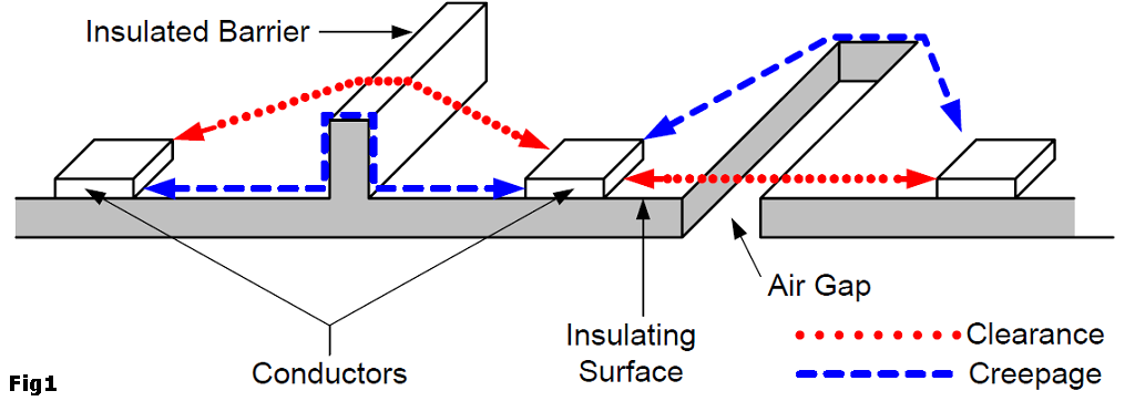
CREEPAGE
The shortest path between two conductive parts, or between a conductive part and the bounding surface of the equipment, measured along the surface of the insulation (Figure 1).
CLEARANCE
The shortest path between two conductive parts, or between a conductive part and the bounding surface of the equipment, measured through air (Figure 1).
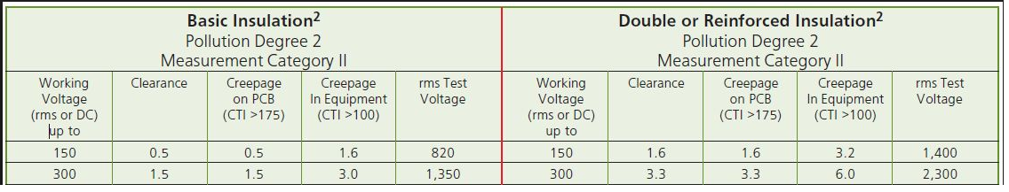
A minimum clearance table for 150 and 300v [Ref]
MATERIAL GROUP / Insulant
DIN EN 60664-1 (VDE 0110-1) divides the insulants according to their CTI values in four groups. These are:
Insulant I: 600 ≤ CTI
Insulant II: 400 ≤ CTI < 600
Insulant IIIa: 175 ≤ CTI < 400
Insulant IIIb: 100 ≤ CTI < 175
[Ref][Ref]
Fr4 material (normal cheap-as PCBs) is normally 175 - 250CTI which is insulation material group IIIa. Ask your PCB house for your CTI value to be able to determine your material group.
POLLUTION LEVEL / Degree of contamination / Contamination level
The influence of the contamination is considered with the calculation of air and creepage distances by degrees of pollution.
- Contamination level 1
No contamination or only dry, non-conductive contamination occurs. The contamination has no influence. - Contamination level 2
Only non-conductive contamination occurs. However, occasional temporary conductivity must be expected as a result of moisture condensation. - Contamination level 3
Conductive contamination occurs; dry, non-conductive contamination which becomes conductive as a result of moisture condensation may also occur. - Contamination level 4
Impurities in the form of conductive dust, rain or humidity result in permanent conductivity.
[Ref]
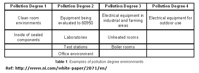
Note that if you put a PCB inside a sealed component you get pollution level 1
ISOLATION/INSULATION
This is one of the most important parts - by knowing your isolation group/type you need to have for safety you enter this into the creepage calculator to get your creepage distance.
“Isolation means that no direct electrical connection, or conductor, exists between two or more circuits or between circuits and accessible parts.” … “You use safety isolation to isolate hazardous, or "live," voltages greater than 30V rms and 42.4V peak or 60V dc from user-accessible SELV (safety extra-low-voltage) circuits. Safety isolation also minimizes the possibility of transient voltage arc-over or -through insulation to user-touchable circuits and enclosures.”[Ref]
Isolation and insulation
Users have access to voltage and current through touchable connectors, cables, and user-interface devices you find on most products. Voltages must be less than or equal to 42.4V÷60 peak dc to meet safe limits and to be SELV. SELV circuits are considered safe to touch and are double-insulated from hazardous voltages in case of a single fault. SELV circuits are commonplace and find use in product inputs/outputs and interconnection, such as logic circuits for printers, PC keyboards, and telecommunications devices.[Ref]
There are five types of insulation: functional, basic, supplementary, double, and reinforced. Functional insulation is necessary only for the correct functioning of a product. Functional or operational insulation does not protect or isolate against electrical shock. Basic insulation is a single level of insulation that provides basic protection against shock. Supplementary insulation is an independent insulation that manufacturers apply in addition to basic insulation to reduce the risk of electrical shock in the event of a failure of basic insulation. Double insulation comprises both basic and supplementary insulation. Reinforced insulation is a single insulation system that provides electrical-shock protection equivalent to double insulation.[Ref]
Double, reinforced, and basic insulations are the most important insulation types for safety isolation. The minimum spacing requirements for safety insulation are double from hazardous live to SELV—for example, 3 mm on printed-wiring board. You use functional insulation between circuits to maintain the operation of the product, but you do not rely on it for safety isolation.
You should use basic insulation between hazardous voltage circuits, but the requirement depends on the applicable safety standard, function of the product, environment, and testing.[Ref]
When a breakdown can create a hazardous voltage on user accessible conductive parts (such as in case of insulation between mains circuits and low-voltage secondary circuits), a double or reinforced insulation is required. [Ref]
- Functional insulation is that which is only
necessary for circuit operation. It is assumed
to provide no safety protection. - Basic insulation provides basic protection
against electric shock with a single level;
however this category does not have a
minimum thickness specification for solid
insulation and is assumed to be subject to
pinholes. Safety is provided by a second level
of protection such as Supplementary
insulation or protective earthing. - Supplementary insulation is normally used
in conjunction with Basic insulation to
provide a second level of protection in the
event that the Basic level fails. A single layer
of insulating material must have a minimum
thickness of 0.4 mm to be considered
Supplementary insulation. - Double insulation is a two-level system,
usually consisting of Basic insulation plus
Supplementary insulation. - Reinforced insulation is a single-insulation
system equivalent to Double insulation. It
also requires a minimum thickness of 0.4 mm
for use in a single layer. [Ref]
How does this all come togheter?
The main question is how much space do I have to have between my traces/components on my PCB to make it safe? To know there are many calculators and tables online. One example is http://creepage.com/. To be able to use these calculators or to read the tables you need to figure out all this above.
For example, we want to know the space between AC traces for a PCB that can be used in all enviroments.
If we enter this into a calculator for example creepage.com we get this:
Insulation: Basic (we know it should be basic from above)
Pollution Degree 3 (for example, we want it to work in areas where condensation occurs)
Material Group IIIa or IIIb (we know it should be IIIb from above since its a normal FR-4 PCB)
Working Voltage 250 Vrms or Vdc
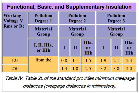
Creepage is 4.0 mm or 157.5 mils
We need 4.0mm between AC circuit to be on the safe side!
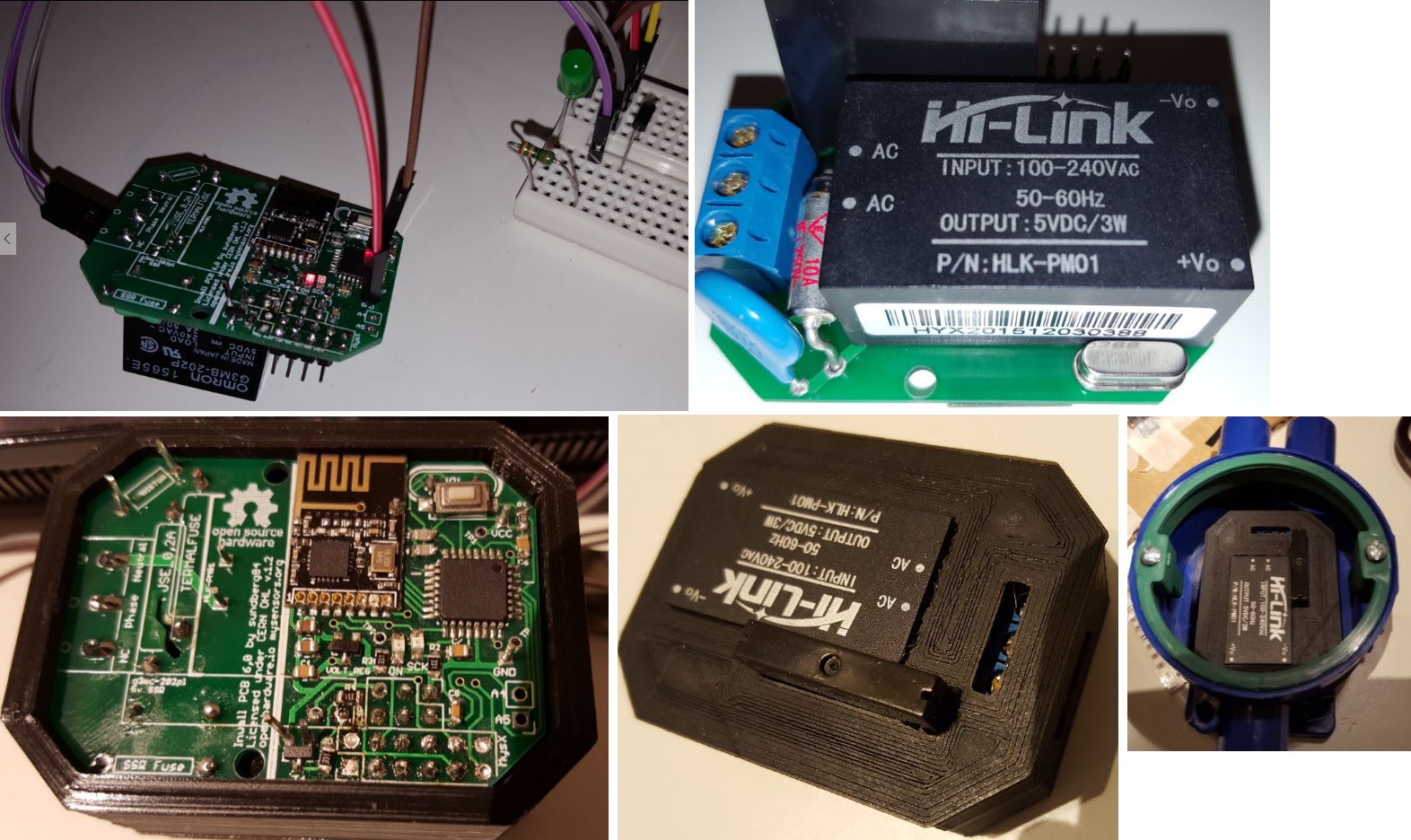
Also if you have a AC (primary) hazardous side and a DC low voltage/SELV ciriut if we want to have a PCB within ALL limits we need to have reinforced insulation and then hits 8mm creepage between AC and DC side.
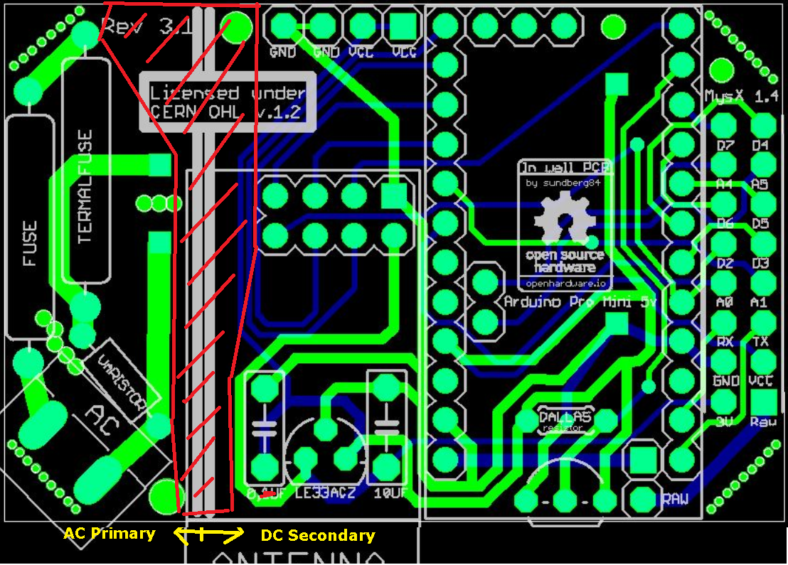
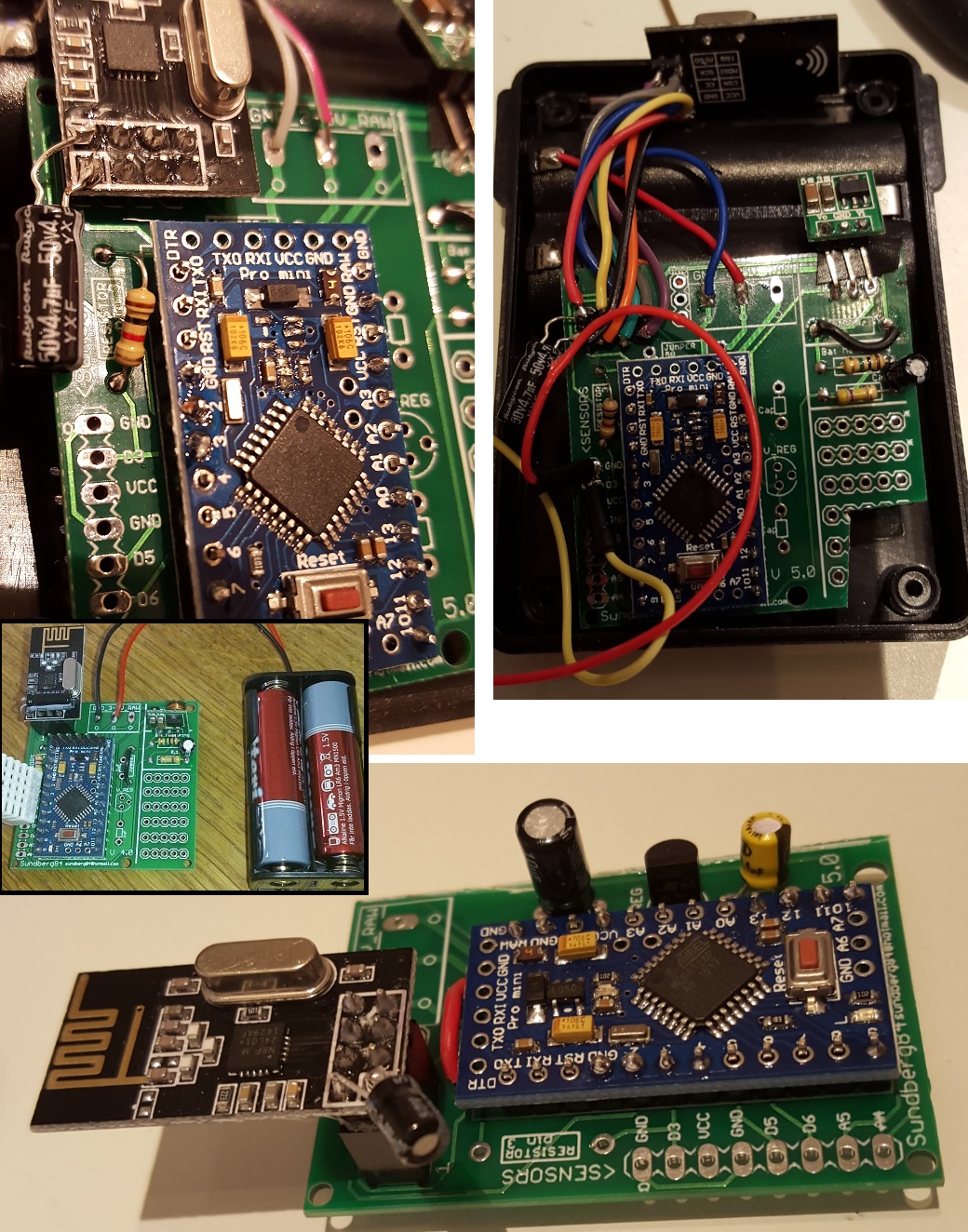
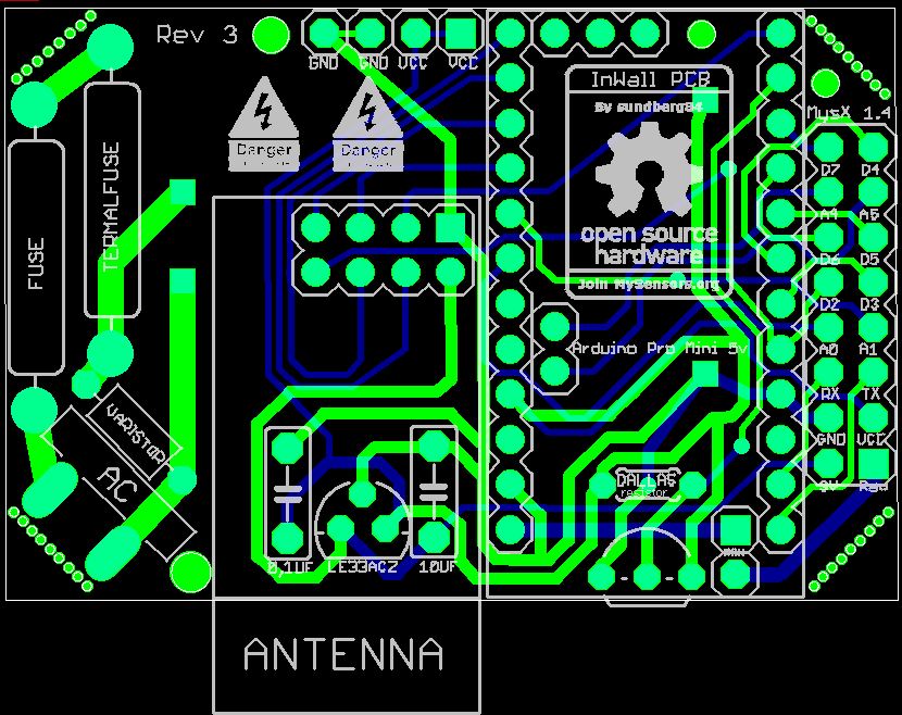
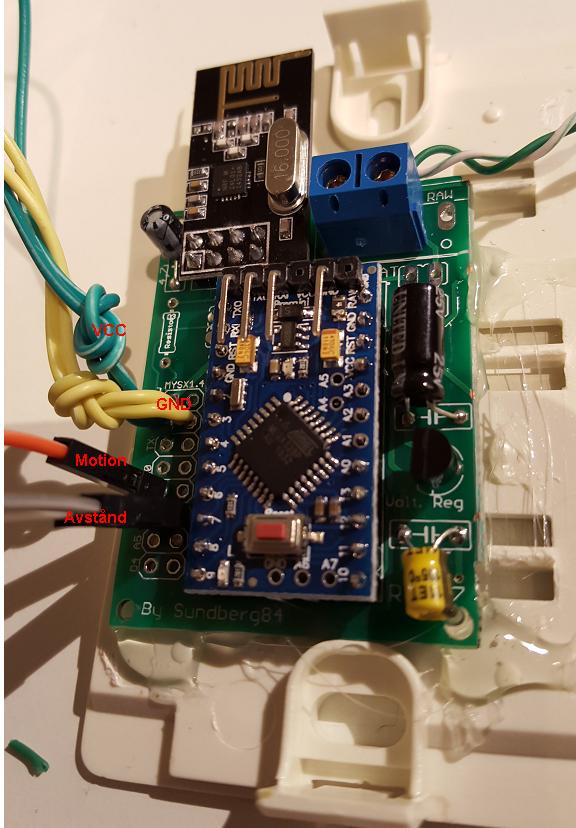
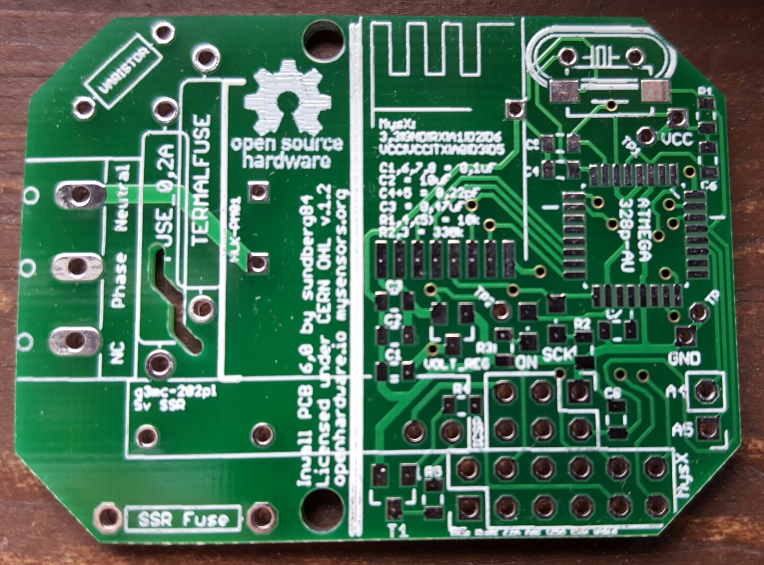
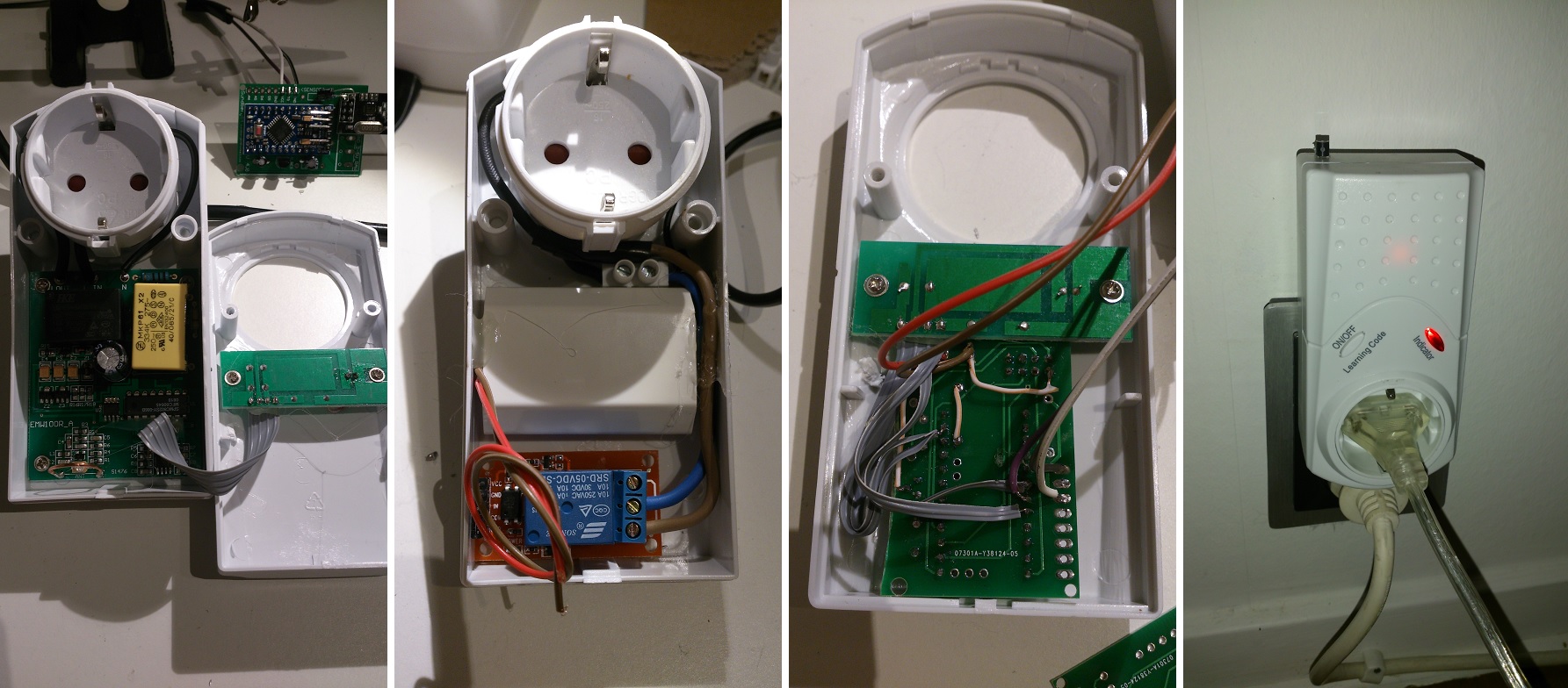
This is a example of a AC primary and DC secondary - but the distance is not 8mm between so it does not meet the reinforced insulation rules if you have a pollution degree of 3 or more.
More about that here:
"PCB shall be constructed so that creepage distances are not less than those appropriate for the working voltage, taking into >account the material group and the pollution degree. Hence creepage distance depends of the CTI's material (Comparative Tracking Index) and pollution degree. European main standard are for Household Appliance (EN60335) and Information technology (EN 60950). As Reference value, in the worst case (Household appliance), for reinforced insulation between High voltage (220 Vrms) and low voltage (<50Vrms) on the same layer (top or bottom), you should an 8mm creepage distance between tracks (Fig. 1) as required for standard EN 60335-1-2, table 17. These distance are lower with better CTI and Pollution degree. If you can’t maintain these distances, you need a milling (cutting of material large at least 1.5mm) between the two points that do not meet the minimum safety distances (fig.2)." (Link)
Same general tip from this article
"A minimum of 8 mm separation between primary and secondary circuits also prevents problems. "
Conclusion
First of all its important to not mix AC high voltage and DC low voltage systems. These should be seperated with a "reinforced insulation".
Assuming MySensors nodes are normally in a normal indoor enviroment (Pollution dgr 2) we need to have atleast 5,0mm seperation between AC circuit and DC circuit if you are using 240v.
Also the distance inside the AC circuit between the high voltage traces should be 2,5mm since this insulation is recommended to be "basic".
Conclusion 2
If you seal your box completely (see IP classifications) to avoid contamination from your environment you can design your board with distansens from pollution degree 1. This means pretty much clearance and creepage are the same. This means you need at 250v 0.56 mm [ref] between AC circuit (basic insulation) and 3.3mm between AC high voltage and DC low voltage. This has alot to do with material quality so I would add some extra space to be sure.
Conclusion 3
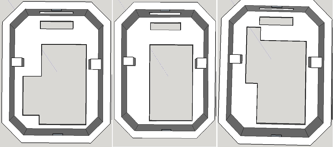
If you can’t maintain creepage distances, you need a milling (cutting of material large at least 1.5mm) between the two points that do not meet the minimum safety distances.
Disclaimer:
My disclaimer is still: I can not guarantee this info is safe! I have not made any professional tests. This is DIY and do not use this if you dont know what you are doing. It may hurt or kill you and damage your property. This thread is more of a question and discussion than a statement. Do not reference this thread. My goal is to figure out the safest way to make a MySensors PCB and the info above might not be correct.
Other Links
http://www.denverpels.org/Downloads/Denver_PELS_20090915_Aldous_Insulation_Coordination.pdf)
http://blog.optimumdesign.com/clearance-and-creepage-rules-for-pcb-assembly
http://learnemc.com/pcb-layout
http://www.itesafety.com/en_e3.pdf
http://sisko.colorado.edu/CRIA/FILES/REFS/Electronics/IPC_2221A.pdf
https://en.wikipedia.org/wiki/Insulator_(electricity)
The end?
Please add your thoughts, questions and most of all knowledge to this thread. I will update the first post to make it easy to find info. Try to keep it in a amature language and avoid technical terms without explaining them.