Hi gad-ofir,
In addition to OH-Documentation you may find some hints in
Part of this thread is dealing with "empty" payloads.
Hi gad-ofir,
In addition to OH-Documentation you may find some hints in
Part of this thread is dealing with "empty" payloads.
Hi gad-ofir,
Warnings may be ignored (for a short time).
What are you doing with UIPEthernet1? Any ENC28J60 chip in Your environment? If so - may be you should use UIPEthernet instead (current version 2.0.6). Beside this - this message is a warning, too.
Check the usual suspects (wrong board? -> if Arduino Nano try "old bootloader", wrong COM port? check Hardwaremanager),
Both Messages give a hint to an improvable IDE. Maybe an update to the actual version could help.
Good luck :slightly_smiling_face:
Hi Gad Ofir ,
You are correct. So far I remember OpenHab assigns IDs. (but if you got a spare Arduino or STM it will not hurt to have one Node with a fixed, known ID -- just for testing purposes).
Your list 1.-3. is correct.
I don't know exactly but from my point of view the logic behind this behavior could be pretty simple: somewhere a list of Nodes has to be kept and the usual Arduino gateways are busy with managing traffic as well as chronically short of RAM and EEPROM. For small networks capacity may be sufficient, but believe me -- MySensors networks tend to grow rapidly. So at last you need an administration Software (aka controller (like OpenHab)) and this may administer the IDs according to its needs instead of keeping and synchronizing double lists.
Hi Gad Ofir,
The Node ID is supplied in the Node Sketch, so you have to modify your PIR sketch (slightly) as shown above.
The drawback of "hard" coded IDs is - you have to compile every sketch for every node individually and you have to keep track of the used IDs to avoid conflicts. For me (about 20 Sensors) it is manageable.
About a year ago i tried OpenHab (2.2 I think). There was a kind of plugin for MySensors and it worked very well. So there is a nice way to bypass MQTT.
I didn't continue OpenHab because it was a slight overkill for my purpose in comparison to MyController which does the trick completely. By the way - MyController seems to work with MQTT too, but I haven't tried it (yet).
Hi @Gad Ofir,
Though I'm not familiar with MySensors and MQTT, this protocol reminds me of my first steps with MySensors when I forgot to assign static IDs for my Nodes and the Controller (e.g. MyController https://www.mycontroller.org/#/home) wasn't up and running. You didn't mention which controller you are using - it should be capable of assigning IDs to nodes.
Copying your sensorlog to the logparser (https://www.mysensors.org/build/parser) shows the lack of an answer to a Request for ID.
I short circuited the whole ID-process by assigning "hard" IDs in the sketch (e.g.
#define MY_NODE_ID 100
This should bypass ID-Requests.
I am not familiar with the exact protocol in the newer MySensors versions so I can't explain the origin of the mentioned ID 237 (???).
In my environment a Node startup looks like:
__  __       ____
|  \/  |_   _/ ___|  ___ _ __  ___  ___  _ __ ___
| |\/| | | | \___ \ / _ \ `_ \/ __|/ _ \| `__/ __|
| |  | | |_| |___| |  __/ | | \__ \  _  | |  \__ \
|_|  |_|\__, |____/ \___|_| |_|___/\___/|_|  |___/
        |___/                      2.3.0

16 MCO:BGN:INIT REPEATER,CP=RNNRA---,VER=2.3.0
26 MCO:BGN:BFR
27 TSM:INIT
28 TSF:WUR:MS=0
35 TSM:INIT:TSP OK
37 TSM:INIT:STATID=4
39 TSF:SID:OK,ID=4
40 TSM:FPAR
77 TSF:MSG:SEND,4-4-255-255,s=255,c=3,t=7,pt=0,l=0,sg=0,ft=0,st=OK:
796 TSF:MSG:READ,0-0-4,s=255,c=3,t=8,pt=1,l=1,sg=0:0
801 TSF:MSG:FPAR OK,ID=0,D=1
871 TSF:MSG:READ,7-7-4,s=255,c=3,t=8,pt=1,l=1,sg=0:1
2084 TSM:FPAR:OK
2085 TSM:ID
2086 TSM:ID:OK
2088 TSM:UPL
2094 TSF:MSG:SEND,4-4-0-0,s=255,c=3,t=24,pt=1,l=1,sg=0,ft=0,st=OK:1
2110 TSF:MSG:READ,0-0-4,s=255,c=3,t=25,pt=1,l=1,sg=0:1
2115 TSF:MSG:PONG RECV,HP=1
2117 TSM:UPL:OK
2119 TSM:READY:ID=4,PAR=0,DIS=1
so there is no request for ID.
@hausinger
Yes, there is somebody - me.
Just like magic - I switched back from my W5100 GW to ENC28J60 GW for testing purposes --- and it is working :grinning: .
Maybe because the node entries in the database were populated by the W5100 GW? I don't know.
I have not changed anything within the GW software or hardware.
So I still think it's a MysController setup issue. Maybe you will succeed using a serial GW for a short time to "initiate" MysController database and then switch to ENC28J60 GW ?? (I haven't tested adding new nodes...)
@hausinger
Bad guess in above posting.
I downloaded MysController (1.0.0beta:b3314:) - just for curiosity.
Yes - I got the same error - connection refused with my ENC28J60GW, which was working fine with MyController just a few seconds ago.
MysController is working fine with W5100 GW - without any configuration change (beside IP address).
I will try some fiddling with MysController - but I am using this program for the first time today.
Is there anybody out there successfully using MysController with ENC28J60 ?
@hausinger
This does not resemble a MySensors message.
I usually get this message when I'm stuck with my SSH connections on Raspberry Pi (lost SSH keys or such things) or due to bad setup - so denial of communication is correct but was not intended.
I don't know if MySensors provides any security functions at this level, but if it does - switch 'em off.
Perhaps you should try to ping your gateway. If there is an answer - i think the GW should be accessible. So it might be a configuration issue at MysController. But this is just a guess.
I am using MyController (without "s"). Actually a ENC28J60 is connected, standard GW software from examples expanded by DHT11 and DS18B20.
This configuration works well since about three months.
@hausinger
Maybe you are using an inappropriate "boards.txt" (i.e. Version > 1.6.11).
Please check posts https://forum.mysensors.org/topic/5786/ethernet-gateway-no-lan-traffic-after-initial-controller-setup/2
and/or
https://forum.mysensors.org/topic/5716/solved-w5100-ethernet-gateway-with-nrf24-stable-mysensors-2-1-0-problem/4
for "repair" instructions.
A "wrong" boards.txt (from Arduino 1.8.0) caused exactly the behavior mentioned above, so this incompatibility (it' probably not a real error) can be fixed with a boards.txt version prior to 1.6.11.
Please keep in mind, every time you update your Arduino IDE, this fix will be reverted.
@HogBil
Seems to be a tricky problem. To get some debug messages you have to hook it to the computer ... and there you won't get any because it's working.
Maybe it is worth to look at debug output from some node. Does it get parent (especially Parent 0)?, will TSM:UPL be ok? At least it would prove your node is working, regardless of network connection.
Maybe you try supplying power via power jack (i.e. 9V).
But this still doesn't solve the problem to get a message without connecting to a computer ..... At the moment - no practical idea leading to any benefit.
@flopp :
No, it isn't that easy.
To improve your NRF, please have a look at https://forum.mysensors.org/topic/1851/extending-range-of-regular-nrf24l01.
I tried solution Nr. 2. It is easy to do and cheap. Improvements are noticeable but not dramatically.
In regard to effort it is worth trying.
If you aimed at changing NRF's frequency - no this is not possible at all. Base frequencies are selected within the chip itself and antenna resonant frequency has to match oscillator frequency.
@HogBil
Did you check your "boards.txt"?
Please have a look at
https://forum.mysensors.org/topic/5786/ethernet-gateway-no-lan-traffic-after-initial-controller-setup/2
respectively
https://forum.mysensors.org/topic/5716/solved-w5100-ethernet-gateway-with-nrf24-stable-mysensors-2-1-0-problem/3
@abrasha
Sorry about the delay - I ran out of ideas, and your new measurements are confusing to me.
About Vin:
Could it be possible we talk at cross-purposes?
From the MySensors wiring advice I conclude to connect Arduino-5V to Adafruit-Vin (just the way NRF24L01 with power adapter board).
From your picture (which I misinterpreted firstly due to bad sight) you said
Well, no, the Vin on the adafruit (brown wire) is connected to the vin pin on the uno. I've tried also connecting it to the 5v pin with no success. Also tried switching gnd sockets on the uno.
Im close to sign this issue with recall to adafruit - i ordered 4 boards and they're all with the same behavior. Or maybe i shorted out the ground when i soldered the antenna?
Connecting Arduino-Vin to Adafruit-Vin would not exactly be according to the rules - but it might work - more likely it would result in unforced errors due to insufficient stabilisation of 5V.
From your measurement 4.99V on Adafruit-Vin I conclude you switched to a 5V Arduino socket - have you?
D13 at 0.2V (or 0.3V) shouldn't light up the LED at all unless its really continuous SCK with predominantly low phases.
To solve this you would need an oscilloscope - and this would be inappropriate in my opinion.
No, I don't think it is a library malfunction. I experienced MySensors library as stable and library malfunctions are mostly detected by community at once. For special cases there maybe a lack of functionality but I don't think your setup is very special (besides the breakout-board). And 5 defective boards in a row - not very likely (and Adafruit has a good reputation for engeneering as well as for production).
I am not familiar with RFM69 (altough I was thinking of adding some RFM69 to my setup, but level converters scared me, so I was interested in your type of setup). So far I read about RFM69 you did the approriate #defines. Maybe someone who is working often with RFM69 could check the above sketch?
None of the above explains why your sketch works without GND connection. It's still a miracle.
And as I said before - I ran out of practicable ideas. Next I would try to get a functional two Arduino system according to Adafruit instructions (as well hardware as software). Ok - it's a little like giving up (only a little) - but maybe a practical approach.
@abrasha
I tested Vin behavior under load on my "original" UNO which displays 4.5V at Vin when powered through USB.
No Load = 4.5V, load 10mA results in 4.2V, load 150mA (which is required by RFM69HCW-breakout board so far I remember) results in 3.8V. Maybe transient load response is much worse than this, but my Multimeter does only 2 measurements per second.
I think it is safe to stay away from Vin on your Arduino (which you apparently are doing already).
According to schematics, "EN" is tied to Vin via 100k. Supplying Vin with 4.99V and measuring 4.4V on Pin "EN" could indicate your multimeter having a relatively low input impedance (about 1M ?). But either way - EN shuts off only below 0.4V, and 4V seem to be a reasonable margin (transients excluded). So this is not the reason for strange behavior.
D13 may be a good point. D13 is tied to Pin 13 (SCK) and via 1k and a (blue?) LED to GND. In my setup (NRF24L01+) there is only a dim flashing when data transmissions occur. So "bright" light on D13 could indicate a permanent data transmission (which your measurements on MISO/MOSI don't support) or there is a noticeable DC component -- which shouldn't be there. Measuring DC on Pin 13 may give a hint.
It is not likely that Pin 13 is our "lost" GND - in theory impedance (especially with a blue LED) is way to high.
To save some time - you got a spare Arduino? Consider building a second sensor (you wrote you got some more Adafruit breakout boards). Take the Adafruit wiring instructions mentioned above and do a close copy of that setup.
Another option would be to exchange the RFM69 module from your GW with the Adafruit breakout boards. If this would be functional - the board(s) are ok.
If you could afford, keep your current setup for further examinations. Although your basic question is quite interesting and unique (my setup works - but it shouldn't) don't get distracted from your way which is probably doing some measurements of your home environment and not of some hardware ( though it is still interesting anyway).
@abrasha
PS: Just found schematics of adafruit breakout board. There is already a capacitor (10µF) across Vin - maybe your additional capacitor has some unwanted side effects?
MySensors building instructions advise a capacitor for 3.3V with range problems - not for 5V.
Adafruits wiring instructions (very nice and instructive picture) don't mention a capacitor either.
Maybe stripping this capacitor will reduce trouble?
@abrasha
Last first: no, I wasn't aiming on current measurement, but it is a really good idea. It would be interesting where does the current come from, and much more interesting where does it go to when you disconnect ground (assuming your circuit is still working without ground connection...)?
Yes, your multimeter should go in series with either VCC or GND.
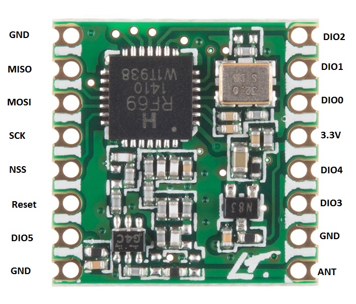
In the photos above the RFM module doesn't match the module on the breakout board. Please have a look at https://www.sparkfun.com/products/13910 here especially photo 4 (and have photo 3 in mind - it has to be flipped over and it is top down).
I tried to label the photo of the RFM69HCW, but I was kind of dazzled by transposition. Please crosscheck this.
 .
.
But either way - your measurements give already some hints. Assuming you are powering your Arduino from USB - where do 4.55v come from? Backward current through your power regulator? Although 4.55v would be OK for the adafruit board (because power regulator needs only 3.5 V to start operation).
Did you measure Vin (from Arduino) under load? Is it capable of driving this load (i.e. does voltage drop down significantly under load)?
Next hint: why ever - 3.2V are generated on your board. So your power regulator (probably AP2112-3.3) is oK. But measuring at RFM- 3.3V connector (under load) won't hurt.
If labeling is correct, NSS = 1.54v doesn't make much sense - it would indicate a high frequent switching action (to be expected on SCK or MISO/MOSI during data transfer). NSS (CS) shouldn't probably switch at this high rate.
miso shows 0v all the time.
There should be at least a little data on miso , so it should not be 0 all the time.
And just for completeness - please measure voltage at "EN" at your adafruit board. Voltage should be constant 4.XX Volts (should be Vin), if not - module is disabled.
@abrasha
Well, I was short of sight (and offset the holes by one...). Sorry.
According to https://www.arduino.cc/en/Main/arduinoBoardUno
The power pins are as follows:
- Vin. The input voltage to the Arduino/Genuino board when it's using an external power source (as opposed to 5 volts from the USB connection or other regulated power source). You can supply voltage through this pin, or, if supplying voltage via the power jack, access it through this pin.
- 5V.This pin outputs a regulated 5V from the regulator on the board. The board can be supplied with power either from the DC power jack (7 - 12V), the USB connector (5V), or the VIN pin of the board (7-12V). Supplying voltage via the 5V or 3.3V pins bypasses the regulator, and can damage your board. We don't advise it.
Vin is used to access power from powerjack - before 5V regulators so it may be up to 12V (minus Diode). Supplying your Arduino from USB this pin should be without any voltage (in theory). So Vin (on Arduino) may not be a good choice to supply power to your extension boards.
Before sending back the modules - you got a multimeter and a steady hand?
Just checking power supply on Arduino Vin, breakout board and RFM module?
@abrasha
Please don´t mind if I am only short of sight, but....
If the pictures show your actual wiring, it seems to me your (brown) GND-wire is connected to the outermost pinhole from your adafruit board. In the photo below this pinhole is labeled with Vin so this should be connected with your orange wire. Your capacitor seems to be mounted accordingly to board labeling. Maybe it is worth checking this.
@mfalkvidd
I am quite happy that this little trick has no hidden side effects.
Would it be a good idea to give a crosslink to @Matt from https://forum.mysensors.org/topic/5426/cant-compile-2-01-for-atmega168/5 ?
I could not figure out how to do this, and cross posting is bad behavior I think.
@xelnaha
Lazy sunday afternoon -got time to "fix" some problems.
Not being capable of reading EBAY item descriptions properly, I got some Pro Mini 168 waiting for some work to do.
Please be aware what the boss says:
The atmega168 is not officially supported, due to the low flash / ram size, compared to atmega328 (tbowmo, ADMIN, 2 months ago)
So far I remember are the Pro mini 168 essentially clones based upon Arduino Duemilanove just without power supply and USB.
Within file "digitalWriteFast.h" in "<whatever>/Mysensors/drivers/avr/DigitalWriteFast/" at line 69
#elif defined(ARDUINO_AVR_UNO) || defined(ARDUINO_AVR_DUEMILANOVE) || defined(__AVR_ATmega328__) || defined(__AVR_ATmega328P__) || defined(__AVR_ATmega328PB__)
I added
#elif defined(ARDUINO_AVR_UNO) || defined(ARDUINO_AVR_DUEMILANOVE) || defined(__AVR_ATmega328__) || defined(__AVR_ATmega328P__) || defined(__AVR_ATmega328PB__) || defined (__AVR_ATmega168__)
because it is not fair to mention DUEMILANOVE and not to give credits to ATmega168.
With this modification compiling and uploading work well.
Please remember:
tbowmo was (is) right about memory capacity. The "BinarySwitchSensor" example sketch uses 14258 bytes from 14336 maximal Bytes. This is a really tight fit. Stripping debug information results in 7604 bytes.