Navigation

    • Register
    • Login
    • Search
    • OpenHardware.io
    • Categories
    • Recent
    • Tags
    • Popular
    1. Home
    2. zboblamont
    3. Best
    • Profile
    • Following
    • Followers
    • Topics
    • Posts
    • Best
    • Groups

    Best posts made by zboblamont

    • Temperature sensor housing DS18B20

      Hadn't seen this mentioned but perhaps I missed it, more plumbing hardware than electronic, but perhaps useful for others.
      Having tried a variety of plates and heat-sink compounds and tie-wraps to hold these little chips in position on small sections of metal pipe (my rads are fed with fused plastic pipe), I came up with the solution of using pipe clips, the cheap plastic variety from DIY stores and hardware merchants.
      The first problem hit was with attaching plated sensor the the boiler clamp nut, it was off by 10c and no way could I get a more accurate reading, presumably angle? Finally found a pipe clip which got hacked in half to fit in the tiny gap in the photo... Some hacking with a Dremel, some soldering to a pin connector, some fiddling around with epoxy and voici....
      20200212_0917332.jpg
      The gap 20200212_094248.jpg
      The tie wrap in the top of the photo is the original plate mounted version which was "off"..

      Having scored on that front with more reliable readings I looked at the roving radiator test kit and realised the same solution might apply so epoxied the chip on the end of some telephone line in a 22mm clamp and it works a treat. Cable and chip fit neatly into the screw-hole, flood with epoxy and done. The pipe it fits is 21.5mm so tighter than a duck's rear end...
      20200218_173908.jpg
      As said, a tight fit to a twinwall radiator feed pipe, and a complete swine to get back off even with pliers, but no broken wires or oopsies to contend with, and so much faster to fit.
      For those looking to measure metal pipe temperatures, possibly an unusual if fiddly solution, but no need of tie-wraps in the latter case...

      posted in Hardware
      zboblamont
      zboblamont
    • RE: What did you build today (Pictures) ?

      Not so much a MySensors build as an example of how even the most basic information can inform changes for the better, in this case space heating.

      The system here is fairly basic, an array of DS18B20s, some ultrasonic tank probes and a gas reed sensor, temperature is updated every 5 minutes, the gas updates every 0.05m3...
      With winters here down to -20, the first priority last year was insulation, and even though a modern house, the gas bills essentially halved over the year, effectively funding not only the insulation, but replacement axial radiator valves and thermostat heads (Heimeier) to replace the typical arrangement of unknown origin, with spare... But now the MySensors impact..
      This autumn's attention turned to the central heating unit, a modern combi unit of good manufacture, installed by a 'certified' heating engineer, but aside what little I knew about condensation boilers and the steep learning curve that followed, I was bemused by the return from the radiator loop almost burning my finger within 10 minutes of the system being fired up. This did not make sense for what I understood of a condensing boilers, which compelled a look inside for the first time, the manual and some googling.

      The boiler is a 25kW combi with minimum output 7.6kW, the radiators account for ca 13kW at Delta 60 set for 15c drop (previously set ca 20c drop), settings since day one were 65c and the pump was set at max output of 3, last year's -20 resulted in 13.5m3/day gas consumed, not crazy by historical records, but hmmm.
      So now comes tinkering with data from MySensors via Domoticz to inform...
      Currently the boiler is set at 55c, the pump is on Low (40 v 84w), but the results are surprising - Slower rising temperature when ON, 42 minutes v 25, but gas use dropped from 0.75 to 0.6m3, but here's the kicker from that longer heating time, not only less energy used per cycle, but longer and thereby fewer cycles per day. Current evaluations are between 15 and 20% savings, so thank you to all the MySensors community and contributors.. 😉

      posted in General Discussion
      zboblamont
      zboblamont
    • An ultrasonic measurement saga finally over...

      Surprised I'm not bald will all the hair pulling and failed attempts to get there but after a year it is finally working...
      The task was simple enough, to measure fluid depth in two tanks, one a sewage holding tank, the other a bulk water tank. Just figuring out which method worked with which board was an exercise in frustration, but the JSN-SR04-2.0 turned out the only one of the two I could get to reliably work.

      Despite the industrial look, these waterproof light switch enclosures proved ideal, as the batteries in holders fitted beneath the clear plastic. A little hacking out of the switch 'fingers' with a Dremel gives plenty of space in the base area.
      Battery holders are held in plastic conduit which are hot glued to the back of the box poking through the front section aperture.

      The top case is a 3v3 WhisperNode with onboard RTC and RFM69, and tucked under the spaghetti in the top left back corner is a level converter. The RTC wakens the Node every hour to initiate readings, and despite a few hiccups seems to be reliable. The WhisperNode is allegedly capable of draining the 2 AA cells down to 0.9v, time will tell...
      0_1528540226816_20180609_124626[1].jpg
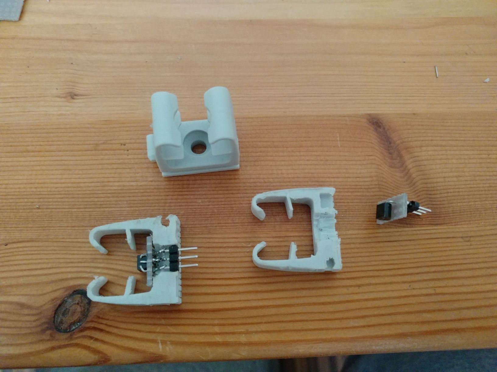
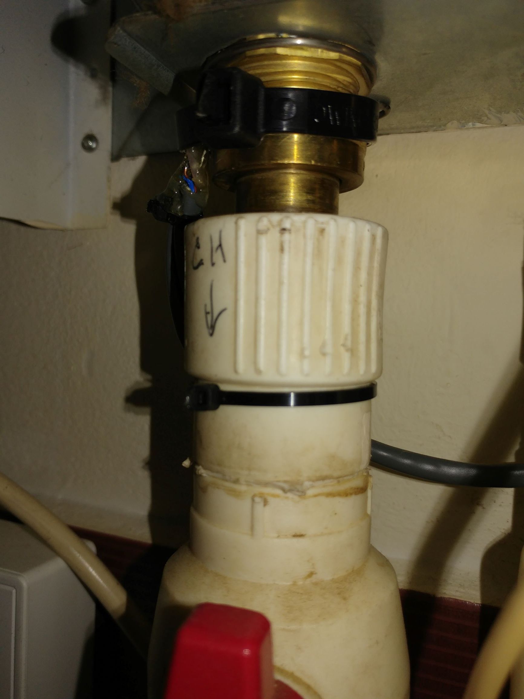
      The lower box holds the 5v ProMini, a small latching relay, and the ultrasonic board, the button type ultrasonic (like parking sensor) is mounted on the end of a 3/4" collar to 1/2" galvanised steel tube drilled centrally through the roof of the 1.34m x 1.67m tank area.
      0_1528540340305_20180609_124611[1].jpg
      Connection between the cases is via Cat5e in 16mm conduit, 2 cores for I2C, 3 cores for relay control and 3.3v power, 2 cores for 5v and ground to the level converter.
      0_1528540419630_20180609_124653[1].jpg
      Despite worries over echoes in the resulting space, the tank was emptied last night, and the reading is coming in with the occasional glitch at 1620mm depth from the head, which I believe has a cone angle of 45 degrees.
      The Node control of a Relay by On/Off pins to Mosfets may seem wasteful, but I had them anyway. The 5ms on/off of this small latching signal relay boots up the ProMini and seems reliable.
      Still to incorporate a WDT/Reset on the 5v as it periodically hangs, and a time limiter on the Node to complete the task, but glad it is all all working semi-reliably, even if some of the programming side I still don't understand...
      The 5v tests for 2 consecutive identical readings, the 3.3v tests that it fits within acceptable range, and if not calls for a further reading.

      Once delivery of a second identical board from China is done, the water tank should be a lot easier. This one is the more important, as ran out of water previously due to corrosion of the level probes in the tank (3 core cable and short bolts) which stopped the borehole pump topping up the tank, and the hidrofor hit it's cut-off electrode. The level monitoring will give early warning to go investigate long before the bulk tank is 'empty'...

      Postscript 12/7/18 - Water tank worked flawlessly from first deployment, but led to concerns over dropping battery voltage.. The problem appeared to lie with the Master sinking power through the I2C lines, but a routine to null the SDA/SCL lines prior to sleeping seems to have halted the decay.
      One of the unexpected results of the Sewage Tank deployment was detecting a dramatic rise in level during a heavy storm (85mm in 24 hours) initially thought to be ground water intrusion.
      Excavation to the incoming pipe connection to the tank found a round pipe in a square hole (not exactly an unexpected building practice here, now packed out and sealed.
      Losing 30% of storage capacity would otherwise never have been detected, so it the deployment has already paid for itself handsomely...

      posted in My Project
      zboblamont
      zboblamont
    • RE: 💬 Arduino Pro Mini Shield for RFM69(H)W

      @pepson This reminds of that famous quotation "Any ship can be a Minesweeper..."
      "Once...."

      posted in OpenHardware.io
      zboblamont
      zboblamont
    • RE: What did you build today (Pictures) ?

      @neverdie Would this work ?0_1515601479151_25004235-474d-4c6e-9a85-5a60dc350f58-image.png

      posted in General Discussion
      zboblamont
      zboblamont
    • RE: What did you build today (Pictures) ?

      @sundberg84 Yeah, this brings back memories, particularly of quite a few hangovers.
      I used 3 and four wide fireclay pipes for bottle storage, they were used for ducts back in the day before plastics took over, cable went optic fibre. I noticed recently here they are back in stock in stores as....yep...wine storage racks.... but wacko pricing relatively...
      The beauty of the fireclay was it's slow temperature and humidity change, and this formed the bulk of the thermal mass in the cellar I made below the floor.
      I used a 150mm glazed ceramic drainage pipe dug in under the garden as a loop (rope caulked joints - anybody remember them), from memory down about 1.5m, both avoiding frosts and baking sun, don't think the temperature varied over a degree all year round, the ground acting as a massive heatsink which maintained a constant temperature all year round.
      Only when the hatch was opened did the temperature jump, a small fan kicked in when the hatch was closed and ran for 30 minutes, a second contact switched on the lights and shut them off, long before LEDs were so prevalent, old reliable (until you were depending on them) incandescent bulbs.
      That was it really.
      Biggest problem I found was humidity in the early days, probably the fresh construction...

      posted in General Discussion
      zboblamont
      zboblamont
    • RE: Fewer home automation postings? What's behind it?

      @tbowmo Hah, you were lucky, I finally upgraded from the monochrome to colour...
      0_1525331364710_d5c5d792-8ab2-479d-a01e-31f43f794f0b-image.png

      posted in General Discussion
      zboblamont
      zboblamont
    • RE: What did you build today (Pictures) ?

      @sundberg84 Easy, one is disconnected... 😂 At 90 degrees? 😜

      posted in General Discussion
      zboblamont
      zboblamont
    • RE: What did you build today (Pictures) ?

      Finally the round-tuit UPS got built after the last power cut clobbered the Controller/Gateway system, lesson learned...
      Meanwell AD-55A, 7.2Ah Acid gel battery, two usb 5v buck converters, a spare socket for raw volts, and a 15 euro IP66 box from the local shops.. Some drilling and filing to the lid, couple of brackets, spare bolts, banding, soldering and hot glue...
      A bit bulky, but disappears in a void under the stairs, two tiny drill holes let the buck converter leds shine threw...
      No monitoring as yet, but sailed through a power cut this morning and the Pi didn't skip a beat.. First up is the Pi's RTC then can put the cover back on the Controller...
      0_1563789698294_20190721_074129[1].jpg
      0_1563789869238_20190722_001114[1].jpg

      posted in General Discussion
      zboblamont
      zboblamont
    • RE: What did you build today (Pictures) ?

      First of the winter projects done, just the programming to finish and replacement temperature chips to get (broke the legs off both DS18B20s through clumsiness).
      With mains/battery backup and RTC, it will record boiler start/stop and run times as well as feed/return temperatures, and as an aside the inevitable power cuts which plague this part of the world.
      The MCU plugs into a socketed backplane hot-glued to the back of the box should removal prove necessary, but quite pleased it is sturdy and all fitted into a slim 25mm deep standard (cheap) box.
      0_1572107113418_20191026_182803[1].jpg

      posted in General Discussion
      zboblamont
      zboblamont
    • RE: Which are trustworthy brands for a simple USB wall charger?

      @NeverDie Was "starting to warm-up" an example of Texan humour, or accidental, given how this thread started off....?

      posted in Hardware
      zboblamont
      zboblamont
    • RE: 💬 Distance Sensor

      @Boots33 Well, finally I got some positive results, but not quite as expected...
      The JSN-SR04T-2.0 nor the DYP-ME007Y I could get to work on all six variations of sketches tried. Still not sure why neither would work using this 3v3 board even with 5v to the ultrasonic board and dropper resistors on the echo. Allegedly the ping from 3.3v should work.

      So, bought and finished today trialling a 5v/16MHz Pro-Mini ;
      The JSN version 2.0 nor the DYP would not respond to NewPing, simply churning out zeroes.
      Other sketches would turn out fixed numbers and zeroes which did not alter irrespective of the transducer/object distance.
      The JSN finally got working with a simple PulseIn calculation loop with a 500 delay. First reading was always Zero, all the rest consistent and rock solid.
      The DYP unexpectedly responded only to the SoftwareSerial method originally found to work from a Russian site. The readings are spot on from the start.

      Now that they work, I need to figure out if there is a workaround for the 3.3v transceiver node....
      Phew....

      posted in Announcements
      zboblamont
      zboblamont
    • RE: NRF24 Range

      @ben999 Power input and output remains exactly the same. If you take an analogy of radiated power as a tyre tube, the larger the antenna the tyre tube is squeezed on top and bottom extending the range and conversely sensitivity. Add a reflector and directors (as in antenna beam - yagi) the radiation is squeezed top bottom and back forcing the a lobe out away from the reflector.

      posted in General Discussion
      zboblamont
      zboblamont
    • RE: Trouble wiring a Dalla 18B20 to Arduino D1 Mini

      @sirzlimz There are two ways to use these devices, the method I found reliable was providing Vdd with power, and power via the drop resistor to the DQ pin (data).
      I suggest trying the direct power method by pulling the jumper from line 21 and stick it into 25.
      If it works fine, then try disconnecting to observe any difference.

      Forgot to say - The configuration you have is called Parasitic Mode, some leave Vdd dead ended, some short ground and Vdd together...

      posted in Hardware
      zboblamont
      zboblamont
    • RE: remote control design idea

      @parachutesj Yes, pretty sure it was @NeverDie who trialed a matrix within the last six months which did what you are looking for, you can search for it on the forum...
      EDIT - Found the thread, farther back than I thought https://forum.mysensors.org/topic/8936/6-8-buttons-battery-remote-node

      posted in Development
      zboblamont
      zboblamont
    • RE: Fewer home automation postings? What's behind it?

      @NeverDie I was answering the original post on potential reasons, not addressing specific complaints.

      Whatever improvements can be brought to the forum will be undoubtedly be welcomed, but as a beginner on this hobby I have fumbled my way around and gleaned considerable help getting started just searching on the site. I would hazard a guess that many others are floating around without taking part in discussions.... It's not as if folks aren't generally friendly and helpful...

      posted in General Discussion
      zboblamont
      zboblamont
    • RE: How to get 5v pulse from a water meter

      Just home so opened the Node case and glad to confirm despite ageing my recollection was accurate.
      This screenshot is common to the PR6/7 using CH2P if it is a undirectional flow.
      0_1569503406456_ad764771-f9db-4636-8556-4dfe0c353137-image.png
      Looking at the circuit afresh I see no reason why the internal input pullup of IRQ should not work either through a drop resistor or possibly direct, since all it does is sink the signal, which the IRQ will pick up as Change/Falling/Low. From vague memory of the sketch, mine is triggered on LOW.
      1 - Unlike Reed switches (my gas reed duration is ca 6 seconds) mosfets are fast, so the pulse duration is so short it will not register on your multimeter hence the perceived uninterrupted 5v. The PR7 spec you posted says 10ms duration...
      2 - If envisaging a standalone radio node such as deployed here, you may be better going with a 3.3v PM to begin with rather than mess about with level converters later...
      Hope this helps...

      posted in Hardware
      zboblamont
      zboblamont
    • RE: Battery: pro mini @ 1mhz vs booster

      In addition to the above, as @Yveaux pointed out the processor can be run almost to battery death, so only the voltage requirements for the sensors may limit your options to running at 8MHz.
      My Nodes were bought as a specific variant with onboard booster, so it is technically possible to build a highly efficient booster, but it's unlikely to come from China's mass market.

      But this then touches on the point made by @mfalkvidd, rechargeables have very different characteristics to alkalines (Google for info on battery comparisons performed by others). I went through this extensively before starting up, and no regrets on alkalines.

      As @Nca78 referred it also depends on load and duration.
      My faster processor executes the radio update on a gas reed trigger then goes back to sleep within ms with no external load, 2 years later the Node batteries read 2v.
      The tank monitor fires a 3v ultrasonic routine at 8mA every hour and maintains an RTC, but aside hourly routines is in deep sleep the vast majority of the time. 6 months in and Node batteries are at 2.89v, so over a year is guaranteed... However, without it's onboard booster it is likely the ultrasonic would have stopped working.

      A further option to where a sensor needs a higher voltage is to switch on a secondary supply specifically for that sensor. I didn't have much joy with that using a booster due to noise, but it worked fine with a battery pack and VR.
      Hope this helps...

      posted in Development
      zboblamont
      zboblamont
    • RE: Fewer home automation postings? What's behind it?

      @nagelc If there is any frustration leading to folks abandoning DIY in favour of commercial offerings I suggest they would have favoured that route to begin with.
      For somebody starting out on this DIY hobby the learning curve can be daunting, the technicalities and terminology may be comfortable for those with experience, it is easy to forget that the learner is essentially trying to decode hieroglyphics in the dark by dim candlelight, ie even the most basic explanations can prove challenging to begin with.
      The problem for any forum will be the level at which the information is pitched, as it has to accommodate so many levels of expertise...

      posted in General Discussion
      zboblamont
      zboblamont
    • RE: DS3231 RTC Module Pin out and operation confusion

      @nafees-ahmed The 4 pins are duplicated on the board, they provide I2C comms only (eg to access current time) but no Interrupts etc..
      The button cell maintains the RTC, if you disconnect Vcc the clock is kept going and it's settings are preserved, so if your board gets a power cut, everything recovers on restoration of power.

      posted in Hardware
      zboblamont
      zboblamont
    • RE: Problem with reed sensor

      @micmuec If I read your post correctly you are trying to use 1940's pump controls via a processor... I do not understand why.
      Incidentally, you would normally express tank capacity as % full, you are doing the inverse, % empty.

      The reed switches will function correctly if the magnetic field closes it, that is a physical issue, nothing to do with your program, so check the proximity of magnet and reed.
      The debounce function is for the computer to avoid false positives on a processor running in millisecond cycles, hence registering a single event rather than every bounce of the contacts (typically 10-60ms). How long does it take before the level moves sufficiently to avoid the reed closing? I suggest you can ignore repeat signals as if the magnet is THAT close it does not matter how many times it registers.
      I suggest that you are looking at ANY contact on the reed is a signal to start or stop the pump, KISS...

      Were it me I would use your latching relay tied to supply via the reeds, one to switch on and one to switch off your relay. I would additionally recommend placing a safety contact above the highest to stop the pump in the event the high contact does not trigger, that is how it was done in the 1940's too, as it saves overflowing and free showers for the neighbourhood.
      The computer is only getting in the way in this case I suggest, use the relay and reeds to control the pump, an ultrasonic or pressure sensor to monitor height, perhaps with an intervention relay from the computer should both the HIGH and the HIGH-HIGH reeds fail to register.
      Old fashioned technology maybe, but...

      posted in Troubleshooting
      zboblamont
      zboblamont
    • RE: Email notifications with planet sized bell

      @mfalkvidd If what I saw as email notification this morning is the result, call me totally impressed by the speed this was dealt with.
      7 hours or less and fixed...
      Bravo...

      posted in General Discussion
      zboblamont
      zboblamont
    • RE: Generic pressure sensors -SOLVED

      As a postscript to my own question should someone be looking at similar later, in practice the sensors were found to work perfectly well at 3v3.
      Described as 5v working, 0.5-4.5v signal range, the effect is pro-rata at 3v3 in terms of voltage but the ADC output is identical for VCC scaling - viz, ZERO pressure is 10% of 1024 the range is 80%

      posted in Hardware
      zboblamont
      zboblamont
    • RE: Efficient LEDs for night light?

      @chbla In addition to @gohan suggestion, if the shed ceilings will take staples or a glue, you may find it easier to cut and fix 5m rolls of 12v waterproof (IP65) LED strings in branches which you can switch out or in to give more or less light... At $10 or less per roll, it makes little sense to make your own...
      If the shed gets damp (and most do), only the joints are exposed to moisture, easily taped or siliconed over. Most tapes come as self adhesive but rarely are reliable, I used a staple gun with staples just over the tape width to fix, no problems.

      Pick your preferred colour temperature, the most efficient lumens/W, order however many rolls needed, done and dusted.. If you need more, easy enough to add more...

      posted in General Discussion
      zboblamont
      zboblamont
    • Water level measurement - Ultrasonics V Pressure

      A quick update on my long running battle to measure clean water tank volumes with ultrasonics, plagued by unreliability and periodic condensation problems on the ultrasonic head.

      As the pump well is alongside the underground bulk water tank, and the pump intake is below the pump cut-off level, it was ideally suited to trial a pressure sensor.
      This solution would equally suit overhead tanks.

      In this case the level range is 820mm, the smallest value screw-in sensor found was 5psi so ca 3.5m of water column.
      With the intended range, this gives ca 6mm steps on the ADC, so not so different to the ultrasonic in terms of performance. Though advertised as 5v units, they work just fine on 3.3v.

      After some plumbing mods the sensor was fitted and hooked up to the Node over 3m away, and has now been working for a month flawlessly (once I inhibited readings when the pump was running 😖 ).

      In all this time the ultrasonic has failed to read despite no condensation issues and several attempts to coax it into life, but at least I have a reliable alternative now...

      posted in Hardware
      zboblamont
      zboblamont
    • RE: Frequency usage regulations

      @mfalkvidd LNA=Low Noise Amplifier, essentially a receive pre-amplifier...

      posted in General Discussion
      zboblamont
      zboblamont
    • RE: Coronavirus (way, way, off topic)

      @NeverDie Thought you might find this informative https://www.livescience.com/how-long-coronavirus-last-surfaces.html

      posted in General Discussion
      zboblamont
      zboblamont
    • RE: 💬 Arduino Pro Mini Shield for RFM69(H)W

      @pepson I suggest you read it again.... The table refers to VCC 3.3v, thereby what is shown NOT a 5v device, the NOTE on that page and which I quoted above spells it out clearly, a converter would be required for 5v.
      If you are supplying it with 5v as well as connecting 5v logic, it is working outside it's specifications, that it is working at all is luck, but magic smoke will appear at some point.

      posted in OpenHardware.io
      zboblamont
      zboblamont
    • RE: RFM69 antennas comparison

      @gohan A straight wire will always have greater actual gain than a coil even though a quarter wave electrically with minimal ground plane.

      On your findings on commercial v DIY coils, they are unlikely to be designed for the same centre frequency, but also typical shrouded helicals tend to be manufactured with very thin wire. The larger wire diameter coil will (even at identical design centre frequency) exhibit a slower rate of mismatch (SWR) as you move away from the centre frequency.

      Where the objective is to use minimal power consumption on a battery powered node, efficient antennae can have significant effect when transmit power can be reduced for the same effective radiated power with a dipole etc...

      posted in Hardware
      zboblamont
      zboblamont
    • RE: [SOLVED] Puzzle over water meter .sensor

      @zboblamont For anybody who stumbles across this same issue using a Elster/Honeywell PR6 pulse sensor, herein the solution found.

      Digging a little further into the documents, Elster recommends for logging etc that the pullup resistor be set to 2k2 connected to up to 30v.
      The pullup was changed out to 2k2 and the Node put on battery power only, but this still continued to register false positives.
      The Node was powered off completely and the PR6 detached from the meter to check mounting even if it was impossible to get wrong, part of the moulding fits under the hinge, and only two screws points clamp it to the meter face.

      The original sensor core connected was CH2P (Red) as Elster recommended, this line compensates for reverse flow pulses (which should never happen on domestic meters anyway).
      The pullup connection was changed to CH1P (Yellow), which outputs all pulses irrespective of flow direction, PR6 refitted, the Node powered up, and no ghosts registered overnight.

      So problem solved...

      posted in Troubleshooting
      zboblamont
      zboblamont
    • RE: NRF24 Range

      @ben999 It should work ok, but may require a bit of tweaking and experimentation to get the correct length. Effectively it is a quarter wave either side but the PCB track also forms part of that antenna so not just a straight calculation.

      posted in General Discussion
      zboblamont
      zboblamont
    • RE: 💬 Easy/Newbie PCB for MySensors

      @sundberg84 Coincidentally I yesterday had a FTDI powered 3v3 Pro-Mini hooked to a RJ11 socket to test and retrieve addresses using the OneWire.h from two plugged DS18B20 devices to add to those in the chain here already, the resistor was 4k7. The chain of now 12 devices also uses a 4k7 and continues to work flawlessly.

      posted in OpenHardware.io
      zboblamont
      zboblamont
    • RE: RFM69 antennas comparison

      @gohan In comparison with a coil, the straight version will always behave more efficiently, but is also easiest to make correctly...

      The issue I suspect your experiment uncovered is matching the exact wire diameter, turns and spacing to radiate precisely at the target frequency. You may find both are labelled as 433MHz for instance, but one is tuned to 470, the other at 435.... The 435 will be less a mismatch to the transmitter, thereby more efficient...

      It is all a trade-off between location and how much intrusion into the space the antenna will be. You could have a node 100m away using minimal power into a full wavelength loop antenna (1/4 wave each side) using a metal shed wall as a reflector, there it does not intrude, in your kitchen it would....

      posted in Hardware
      zboblamont
      zboblamont
    • RE: Spam postings

      @dbemowsk Absolutely...

      posted in Troubleshooting
      zboblamont
      zboblamont
    • RE: NRF24 Range

      @ben999 Ooops. PS - orientation of the antenna must be the same for send and receive, usually vertical. Do not mix polarisations it will attenuate signal strangth. Have no idea if the board itself would disrupt signal but would play safe and have the antenna end facing intended direction of receive.

      posted in General Discussion
      zboblamont
      zboblamont
    • RE: Raspberry Pi/Motieno - Serial or Ethernet Gateway?

      @philbolduc I suggest looking again at the MySensors intros, the terminology will click..
      Your Pi3 will host the management platform of your choice (Domoticz, etc..), and is usually referred to as the "Controller". The Controller communicates with the Hat which is your Gateway, over the serial connection. It is the Gateway outward where the MySensors environment kicks in.
      In your case the Hat should be programmed as a MySensors Serial Gateway (Moteino site has a clear how to).
      The Gateway thereafter communicates with your MySensors Nodes via the rfm69s, and back to the Controller over serial.

      Whether you elect to go wifi or ethernet from the Controller outward is entirely up to you, but is external to the MySensors environment.

      posted in Development
      zboblamont
      zboblamont
    • RE: RFM69 antennas comparison

      @sundberg84 Sorry, yes there will be a loss.
      This site may better demonstrate it graphically down the bottom...
      link text

      posted in Hardware
      zboblamont
      zboblamont
    • RE: Battery percentage gone wild [SOLVED]

      @gohan Something doesn't make sense here, if the onboard voltage regulator is removed and battery power is connected to Vcc via a booster it should provide a constant supply.
      If the divider to A0 is fed with the raw battery supply, it should be relatively constant although decaying over time.
      Something is wrong with the circuit I suspect....

      posted in Troubleshooting
      zboblamont
      zboblamont
    • RE: Doorbell detection

      @Puneit-Thukral Perhaps an outline of your circuit and what is sensing what may help narrow down the issues. Were I looking at something which fires an LED, there is DC supplying it, which should be easy enough to tap (low voltage DC line) to initiate a response from your node. I would be inclined to test a signal input to light onboard LED on external LED lit, then refine the sketch to carry out the action so it narrows problems to a software issue.... Right now this is Stevie Wonder playing golf in the dark....

      posted in General Discussion
      zboblamont
      zboblamont
    • RE: How can I monitor the humidity of a wall (house)

      @8667 I believe that is what @bjacobse was referring to, but zero response from @pierrot10 in the last 4 days, and no indication this study has some physical outcome rather than a potential data study.
      I agree, and at the risk of parodying Trump, fix the goddam wall...

      posted in Development
      zboblamont
      zboblamont
    • RE: RFM69 antennas comparison

      @sundberg84 The way to imagine field strength on an antenna is that it is circular looking on the end of a dipole, varying in strength from essentially zero at one end to max at the centre back to zero at the other end.
      Under ideal conditions, the field is like the balloon explanation in the other link. Unless your receiver is hugely different in height to the sending antenna, the reception will be identical throughout 360 degrees at the same distance.
      Rotate the antenna 90 degrees however and the the field forms principal lobes to front and rear, max facing centre on both sides, reducing to minimum facing the ends, viz this which makes the antenna directional compared to it's vertical orientation.

      posted in Hardware
      zboblamont
      zboblamont
    • RE: How to start using a Pro Mini?

      @eddiever I mean no offence by this, but might it not be wiser to describe what you are trying to do so that you might be better informed what to get and why, rather than to make a wild guess ?
      For every success on this forum there are a hundred who failed and could readily advise you not to do as they did... 😉

      posted in Troubleshooting
      zboblamont
      zboblamont
    • RE: I need advice with brainstorming my farm project

      @NeverDie The penalty of higher amplification electrically is power consumption, gain is also a function of antenna type and directivity.
      Farms are rarely in an urban area likely to cause interference. Even low power uhf on a dipole should link 1km, but for certain a colinear or small yagi should transceive no problem without the penalty imposed of slower data rate on Lora, or the consumption issues of higher power....
      Worth considering I suggest....

      posted in General Discussion
      zboblamont
      zboblamont
    • RE: Power ON node

      Perhaps if you power a Node with a PSU with battery backup you can detect if the mains fails that way?
      That is the arrangement I have with the central heating boiler as it senses the 24v relay differential which reduces to zero when the contacts close. As this would also result from power failure, the Node monitors both VIN and Vrelay to verify Power On/Fail, Boiler On/Off....

      posted in Development
      zboblamont
      zboblamont
    • RE: How to power 5V sensor?

      @sundberg84 The details and methods to release additional pins are all in the documentation, so not a problem, however my original idea was to have capability to swap over devices, hence my reluctance to do surgery.

      Low energy use info is plentiful on the 5v pro-mini, the booster is the PIA for low energy, so that will probably be relay controlled in any instance...

      A steep but interesting learning experience...

      posted in Hardware
      zboblamont
      zboblamont
    • RE: Multiple Dallas Temperatuur sensors at one sensor node

      @dzjr Assuming it is not a wiring problem, I suggest running a temporary test sketch on the Node to ensure you are communicating with all the OneWire sensors.
      Once local communication with all 5 is confirmed, then check your original sketch to see how all 5 devices are presented and identified to the Controller, or whether the Controller assigns Child IDs (not ideal for multiple sensors), and reload your original sketch.
      Next check that all 5 show up on presentation to Domoticz, they should list under hardware even if only become active once temperatures are first reported.

      If you have not done it this way, the table/array method is highly recommended for multiple sensors -
      My 3v Node sketch lists 12 DS18B20s with their unique digital addresses, presenting preset Child IDs to the Gateway, and reporting temperatures against those fixed Child IDs. They cannot be re-sequenced by the Controller, and I know precisely which device has failed when and if it does, none have.
      Should a chip fail, the digital address can be rewritten in the sketch and the reporting will continue against that fixed Child ID.
      The same array sequence is used to request temperatures and all report to Domoticz every 5 minutes unless the previous reading is unchanged.

      posted in Troubleshooting
      zboblamont
      zboblamont
    • RE: I need advice with brainstorming my farm project

      @NeverDie Jeez, why so negative?
      Why would anybody want to use a network analyser for an antenna?

      If you meant a Grid Dip Oscillator, I made one many moons ago but never used it once. Go figure... Have used a SWR meter to tweak an antenna to 1:1, but usually found it was <1.5 as built which is fine.

      A dipole using straight wire is well documented on these forums and elsewhere, a plate wire or corner reflector spaced correctly forces the lobe in the intended direction with zero effect on SWR, hence making it higher gain, adding reflectors adds to that gain as it narrows the radiated lobe, simple well established science.
      1km should be easy enough on a dipole anyway with line of sight, a reflector or director simply boosts the gain with no hit on consumed power.

      There are a multitude of Ham origin DIY designs for the same band, the commercial J-pole I pointed to was a DIY design, the Slim-Jim a DIY variant on that (from memory a version using the coax only, the commercial ZL again a Ham DIY original, none of this is ground-breaking or difficult to research, but we are talking very long distances with such gain...

      posted in General Discussion
      zboblamont
      zboblamont
    • RE: Battery: pro mini @ 1mhz vs booster

      @kiesel "I think I need to stick with a booster anyway, I am using a light sensor in most of my nodes and it needs 3v." - Don't make the mistake restricting the solution for different voltage requirements to boosting only, they do create noise which can cause problems.
      eg - If you can switch the higher power only when needed (to reduce energy) and use a level converter to talk to the processor, you can use a separate battery source, or increase the principal supply to 3xAA tapping off 2AA for the processor, etc., if space permits...

      posted in Development
      zboblamont
      zboblamont
    • RE: Easy/Newbie PCB for MySensors

      @sincze I have 10 of these DS18B20s strung over approximately 12m monitoring all rooms on both floors of my house and two side lofts, all running on 3.22v from a Pro-Mini. Never have skipped a beat, reporting every 5 minutes, well, aside from a telephone socket which pins went walkabout (the chips are crimped to RJ11s).
      There is something not right with the physical arrangement if you can get the same circuit to report at 5v...

      posted in Hardware
      zboblamont
      zboblamont
    • RE: Multiple Dallas Temperatuur sensors at one sensor node

      @dzjr Sorry for any misunderstanding, the loops I was referring to are the sensor cable loops in your photo.
      I did read somewhere that different pullup resistors were recommended by different suppliers of the waterproof versions, values from 10k to 2k2, rather than the usual 4k7, some said the pullup should be on the Arduino end, others on the last sensor on the line, so worth experimenting, perhaps even a sacrificial length of additional cable to alter or extend spacing ?
      What is crucial to these devices is digital signal timing, hence constraints on layout architecture and cable capacitance, the pullup resistor only alters the circuit's speed of High/Low transitions.
      Here bare DS18B20s on Cat5 cable (low capacitance) works fine on a 3v Arduino for 12 sensors, so it can be done.

      posted in Troubleshooting
      zboblamont
      zboblamont
    • RE: Fewer home automation postings? What's behind it?

      @NeverDie I would tend to suspect there is already a treasure trove in all the fora for folks to dig into, which saves answering repetitive questions, hence reduced postings....

      posted in General Discussion
      zboblamont
      zboblamont
    • RE: Battery: pro mini @ 1mhz vs booster

      @kiesel Bluntly, you won't until it does not behave as expected....
      Example - At one stage I had a second promini on 5v from a booster working the ultrasonic, all ok and signals passed on I2C to the Node via a level converter. When I tried using the ultrasonic direct off the booster, periodic results or nada. I finally figured out the VR on the pro-mini was attenuating the noise, tried various filters but none worked. I ultimately solved the problem using a separate 4xAA stack and a VR, no noise but bulky. But the trick was switching it on only when required, 4 years plus life was eminently possible...

      As @sundberg84 commented, without a scope you are on a hope and a prayer as far as noise is concerned, that is why I suggest a secondary cell may be your solution if it does 😉

      posted in Development
      zboblamont
      zboblamont
    • RE: Temperature sensor accuracy comparison

      @wes Nice.... Perhaps this could be expanded to operating range also?

      My reasoning is my own case where I had already plumped for a chain of DS18B20 on a long Cat5e in the house, one-wire to rule them all 👍 .

      The problem I had was requiring two external sensors capable of -10 down to -25c at opposite ends of the house, the only solution I could see being two dedicated nodes.
      Only after re-reading the spec did it dawn on me the chip range was -55 to +125, but at reduced accuracy of +/- 2. Made a few enquiries, and was advised accuracy at -25 was typically less than +/- 1 so I saved on two nodes by extending the existing chain both ends and living with the lesser degree of accuracy, all the same devices....
      YMMV...

      posted in Hardware
      zboblamont
      zboblamont
    • RE: What is the correct way to implement a WDT, for reset on a Sleeping node?

      @njwyborn Ditto on the stated voltage for the two ultrasonics I have, they didn't work reliably at 3.3v if at all, but the common pro-mini has an onboard booster down to <1v input from 2AA alkaline.

      I can only observe on the two different solutions I trialed, both of which used a a small DPDT latching signal relay fired by mosfet triggers. (ca 50mA for 6ms On/Off)
      The original uses a Master 3.3, the relay firing a Slave 5v pro-mini on a 6v battery, in turn powering the Ultrasonic and doing all the processing then passing results on I2C via a level converter to the Master to radio in.
      The second uses only the 3.3, the relay powers up a step-up to power from RAW for the ultrasonic and level converter, turned off after either a correct result or 10 attempts.
      The first is reasonably frugal but uses 6AA in total, is clunky, problematic, bulky.... Probably it will be changed to the 2nd version when the snows clear.
      The second version is only 3 months in, but thus far seems reasonably frugal on the 2AA cells, probably >9 months battery life.
      In both cases the problem of power demand was identified as the ultrasonic head developing a drip blinding the head, hence the max X attempts to minimise battery drain when it doesn't get a reading.
      The second version is for sure the simplest and most reliable.
      Not sure how efficient the 5v booster is but the greatest power loss is probably the remaining LED on the 5v booster (US LED was removed).
      The pins on the pro-mini used for the relay are the onboard LED pins which I'm reluctant to remove as they confirm the hourly routine and whether the result was successful or not.
      You might try a variable voltage to the Ultrasonic to see where it falls over, but be careful if the pins on your board are not 5v tolerant (hence level converter)
      Hope this helps.

      posted in Troubleshooting
      zboblamont
      zboblamont
    • RE: What did you build today (Pictures) ?

      @sundberg84 Did you find that taking the cover off improved the accuracy at all ?
      😆

      posted in General Discussion
      zboblamont
      zboblamont
    • RE: What is the "robust" way to sleep / send messages?

      @Encrypt It sounds as if you are making progress, moving off breadboard will certainly make for greater reliability.

      My reasoning for checking HIGH and LOW is that these are fixed states rather than in transition. FET type sensors are very fast, but the Elster Water Meter Node would send an intermittent false increment (No idea why/what), which is why the additional check on pin state was introduced.
      That pin check was spurred by experience with the Gas Node, which gave rapidly escalating readings, found to be caused by the reed closing for ca 6 seconds. Checking in a Sleep loop that the pin had changed back from LOW to HIGH before going deep sleep resolved it, 3 years on it's still in complete sync with the register.

      posted in Development
      zboblamont
      zboblamont
    • RE: Temperature sensor accuracy comparison

      @wes Perhaps a Table pinned in Hardware might be the most logical location...?

      It was geniuses here that this noob picked it up from, including crimping the DS18B20s into the plugs.
      In my own case I used small white low profile telephone sockets to blend into the decor unobtrusively, and crimped into RJ11 not RJ45, but the same principle applies...
      If you can line the legs up right and allocate the 3 cores required, swapping out is easy and uniform.

      So long as the one-wire layout rules fit your network as installed, you're good to go....

      posted in Hardware
      zboblamont
      zboblamont
    • RE: What is the correct way to implement a WDT, for reset on a Sleeping node?

      @njwyborn No offence intended Nigel but perhaps you might stand back a little from the WDT and solar concerns, and concentrate on the efficiency of the Node.
      I've just graphed the 2AA alkalines for the US Water Tank Node, as attached :
      ![alt text](0_1551454531985_cb4d7594-5461-459e-b4d8-9cb1cfaf02df-image.png image url)
      This Node sleeps between hourly wakeups from the RTC, and aside the initial drain in January prompting me to limit the program sample loops, there has been no dramatic voltage drain, it probably will exceed 4 months. There are no smoothing caps at all in circuit aside what are on the boards, and it has never skipped a beat aside from condensation build up on the sensor (<-5c I noted) causing an abort from sending in a crazy reading or after 10 attempts without success.
      Presumably you have a need for 10 minute samples, but am completely baffled on running the JSN constantly. It takes <100ms to warm up from the latching relay kicking on with zero consumption, and aside from the drip events has proven reliable...
      Will change the conduit from gunbarrel to plastic over the summer as I suspect the condensation source is the tube (heatsink to external -5 to -16), but putting off the solar charger notion until I figure out whether it causes more problems than it's worth, and watching your progress accordingly.. 😉

      posted in Troubleshooting
      zboblamont
      zboblamont
    • RE: CNC PCB milling

      @neverdie From memory the guy got it off with a hub-puller, and a persuader, but the point I was trying to make was that there is a collet assembly for the ER11which takes 8mm...

      posted in General Discussion
      zboblamont
      zboblamont
    • RE: HELP WITH MYSENSOR PROJECT

      @topgun78 I had a notion to zone control as I viewed it much the same as you have outlined, why heat the house when you're out for the day, but was surprised when I experimented to verify it.

      Gas and temperatures were monitored on Domoticz, but we do get pretty harsh winters here, ymmv. All the rooms had their own thermovalve settings.
      Most expensive to cheapest energy users were:
      Turn off rads in unused rooms.
      Turn down heating overnight.
      Turn down heating when out.
      Heating all the house 24/7.

      It sounds counter-intuitive until you consider every house has an over-rated boiler, and a combi boiler's efficiency tails off as the return temperature increases.
      There is a minimum heat you must dump before the boiler protects itself by shutting down. ie- how few rads must be available to sink the heat.

      I made a portable node with two clip-on DS18B20s to ensure all my rads return high temperature almost simultaneously to the boiler (ie balanced) over numerous heat cycles, so the majority of the heating is at max efficiency.

      I fully understand what you are trying to do and why, all I'm suggesting is decent rad valves and a fully balanced system will save you much more. 😉

      Good luck anyways..

      posted in Development
      zboblamont
      zboblamont
    • RE: Sonoff 433 bridge

      @alexsh1 I use 433MHz exclusively for local networks as it has proven completely reliable and resilient, and I am far from being alone..
      Your " I do not think you'd find a lot of support for 433Mhz around" may prove a flawed perspective. Frequencies and traffic are increasingly cramped, no more so in the burgeoning 2.4 and 5GHz environment, 433 etc are of increasing interest I suggest, not less..

      posted in Hardware
      zboblamont
      zboblamont
    • RE: Increse/Decrese a value with a button

      @dzjr Delay incrementing via a while loop with 50-500ms sleep/wait, to check the button has changed state before proceeding. Modify delay value to suit.

      posted in Troubleshooting
      zboblamont
      zboblamont
    • RE: CNC PCB milling

      @neverdie I used to use nail varnish on threads as it was just as effective, even though it annoyed the partner whose nail varnish it was. It is not the bond between the metals which is that important, it is adding resistance between the threads to prevent unscrewing, were it to completely bond, you would shear the bolt before it was removed, which is a whole lot of trouble....

      posted in General Discussion
      zboblamont
      zboblamont
    • RE: HELP WITH MYSENSOR PROJECT

      @skywatch My apologies for derailing the topic, yep, got two of the boiler feed and return also, and tapped into the trigger wire to notify boiler ON/OFF so Domoticz tracks the run time per day.
      12 degrees is recommended across the radiator but it's not quite so simple, it also matters WHEN you get that differential -
      That's where the portable node came in. Plastic pipe clips held sensors on the inlet and outlet pipes of the rad, the downstairs 6 all had a 11-12c differential at around 16/17 minutes, but no way would the upstairs 3 get there before the boiler cycle ended (room thermostat), which I put down to longer pipe runs.

      I increase the rate on the thermo-valve (pressure agnostic) to get the same heat on the return at ca 18 minutes. Rinse/repeat the remaining 2, eh voila. Balanced, a nice little peak on the return flow temperature at the boiler, reduced gas bills and every room +/- 0.5 of it's set point.

      Actual differential of these 3 upstairs radiators will be WAY under 12 for a constant feed, but for a heat cycle of 19-25 minutes depending on outside temperature it's perfectly balanced before the cycle ends.

      posted in Development
      zboblamont
      zboblamont
    • RE: Water pressure sensors?

      @rwoerz Partly true.... There are multiple effects on a compressed air pipe in water (condensation, gas absorption, etc) which reduce effective air volume and pressure over time, but these are in reality very small.
      Blowing the pipe clear before every measurement is an ideal datum but is generally impractical other than in industrial locations. In reality, a periodic purge with a footpump to an inserted tyre valve on the pipe will restore pressure accuracy for many months at a time for a static well scenario.
      The circumstance posed by @mfalkvidd originally is quite different in that a CSO or SSO is a surcharge arising from periodic rainstorms rather than a constant submergence. If the sealed pipe is installed at a level with free discharge when flow abates, it will function very accurately as it compresses from a natural state. All that is required is to add the height of the pipe to Invert and the actual level can be derived. The bigger problem would be installing a 10m rigid airtight pipe..

      posted in Hardware
      zboblamont
      zboblamont
    • RE: ds18b20 on 2xAAA battery

      @pihome Perhaps re-evaluate what you are trying to achieve and how?
      The array in my place reads every 5 minutes over a cable array, even for outside temperatures half-hourly samples would probably be fine, this is my screen-shot.
      0_1559412067482_d341a047-155e-4672-bd5e-dcf7c909fda7-image.png
      Frankly your goal of 1 minute granularity makes no sense with real world temperature variations, even in interior spaces. If the objective is heating control, room effects are slow.
      If necessay you could up the sample rate when heat is circulating, thence minimise wasted yet finite energy?
      Even the choice of radio may be inappropriate to your energy efficiency goals, I explained previously how this end works, @nagelc has outlined he is getting super performance with 2+ years battery life, this perhaps merits review...

      posted in Troubleshooting
      zboblamont
      zboblamont
    • RE: CNC PCB milling

      @neverdie Torquing down correctly normally prevents threads unwinding, but have seen bolts come loose with vibration on occasion. Only ever used loctite or equivalent on cylinder head bolts, particularly alloy heads, it never actually sets solid and is oil etc resistant.
      Although lacquer or plastic paints do harden, as a plastic filler between the threads, it increases contact friction, yet will shear to permit removal of the bolt when necessary. Typical threads do not fully engage metal to metal, the clearance is essential to allow the nut to be run on the bolt.
      Loctite is fine if you have it already, nail varnish works fine for me in non oily scenarios.

      posted in General Discussion
      zboblamont
      zboblamont
    • RE: 💬 Distance Sensor

      @jjk If the readings you ARE getting are accurate when moved to new positions, it could as @ben999 said be inaccurate alignment to the reflective surface, or as was commented somewhere else, the plug/socket on the board being loose.
      With a 3/4 to 1/2 reducer on a 1/2 pipe ready here for final installation, I sat transducer the socket to take out movement or alignment issues, it drifts off quite readily if angle is wrong. The code Ben refers to for this DYP gave me a slightly lower but not silly first reading then consistent results thereafter, no zeroes.

      Please note that I had tried all 6 sketch variants on the 3.3v device with a 5v DYP supply and got nonsense. Using the 3.3v Trig with drop resistors on the Echo neither the JSN nor the DYP worked properly despite the 5v power from the separate booster supply to them.
      I only found consistency using a 5v pro-mini, with the DYP power supplied from logic pins, which leads me to think Trig and/or Echo are also 5v sensitive, contradicting previous advice and complicating my layout.

      Have not yet got round to trialling a logic converter from the 3.3v pro-mini for Trig and Echo with the original 5v supply, which is the next step, will report back once I get some time to test.

      posted in Announcements
      zboblamont
      zboblamont
    • RE: 3.3V water flow meter on batteries?

      @raptorjr A bit vague on flow range, pipe/channel, inside/outside, accuracy required....
      If it is a piped flow of clean water, a standard domestic water meter (new or second-hand) with a pulse output (reed or fet) would be my choice. Usually the meter design dictates pulse (1, 10, 100 litres) accuracy, the advantage is that no power is consumed other than to respond to the interrupt as @mfalkvidd outlined, and you have the register to cross-check results.
      I have a plastic bodied fet type (not cheap for the sensor) in the house reporting every litre back to Domoticz since last November, two AA cells currently read 3v, they will die at 0.9v sometime in late 2019 or 2020.
      I also have a gas meter reed sensor (same principle) reporting over the same period, with the same battery condition).
      Zenner and B-meter etc water meters are available down to 10 litres/pulse, the Zenner sensors are silly money but the pocket for them takes a cheap small reed switch which serves the same purpose. There are also cheap chinese apartment style domestic meters also around with reed built in.

      IMHO anything else is going to bring more problems over power supplies and accuracy...

      posted in Hardware
      zboblamont
      zboblamont
    • RE: ds18b20 on 2xAAA battery

      @pihome Not sure why you are looking for a sketch problem if the issues don't arise >=3v?

      That some folks have ds18b20 working below the specified minimum of 3v is pure luck, but even were you to source devices which could work down to say 2.8v, it still does not address their certain disfunction below it, particularly down to the 1.9v drop off voltage of your radio, which was your objective?

      Your options are limited to swapping to a sensor (?) which works down to 1.9v, switch on/off a separate supply for the ds18b20, or run a full-time booster for the entire assembly to suck all life from your batteries. It is this latter scenario here, but designed and built by folks clever than I.
      Very tempted after this to look at switching on/off the ds18b20 array's power and see how long it lasts on batteries aloe, perhaps a rainy day or winter project.

      posted in Troubleshooting
      zboblamont
      zboblamont
    • RE: CNC PCB milling

      @neverdie Tinfoil?

      posted in General Discussion
      zboblamont
      zboblamont
    • RE: 💬 Distance Sensor

      @ben999 As a postscript to the above, I puzzled over how quickly I could get a valid result before being able to power down the secondary circuit of relay, booster, level converter etc...

      I looked at the results coming in (in this case from the JSN sensor) and read up on median analysis and gave up pretty quickly on that level of sophistication, as I realised only the first result was incorrect, that puzzling zero, all the rest were consistent and repetitive.

      Inserting a while statement in the Void Setup (instead of the forever version in the Void Loop) checking the time duration < 1, I got a valid result immediately after the first ping, and the secondary circuit could be shut down.

      As I only need one valid result to switch the relay off and radio the reading in once and hour, this seems to satisfy my requirements while limiting power drain on the secondary circuit.

      posted in Announcements
      zboblamont
      zboblamont
    • RE: 3.3V water flow meter on batteries?

      @raptorjr You are not looking for water flow at all, you simply assumed you were...
      Perhaps a sampled differential pressure sensor, or a differential pressure switch might be your solution ? 😉

      posted in Hardware
      zboblamont
      zboblamont
    • RE: Neighbor kicking me off my own mysensor network?

      @les Perhaps your first guess is wrong and the Node is kicking itself off because something mismatches?
      I'm never used MQTT or encryption as never really saw the point with rfm69s, but it makes no sense that a neighbour would know your networkID and the Node number before and after you changed it?
      Did you establish communication worked on a simple serial gateway first with no encryption or is this your first attempt?

      posted in Troubleshooting
      zboblamont
      zboblamont
    • RE: CNC PCB milling

      @neverdie Perhaps surface cleanliness is the problem rather than the tape, just a possibility... When you are dealing with such fine tolerances, any residue will allow the board to twist or warp...
      Not sure to what extent the milling itself would encourage deformation of the substrate, but irrespective, it would again depend on adhesion on the bottom face to resist it...

      posted in General Discussion
      zboblamont
      zboblamont
    • RE: 💬 Building a Raspberry Pi Gateway

      @pepson Just a suggestion, but are you sure the Pi3 is looking at ttyUSB1, ie have you confirmed this is the Gateway serial connection ?
      I am using direct serial connection to the pi3 GPIO as ttySO with Domoticz, but when I tried a USB Gateway at one point, the connection was NOT working using the expected ttyUSB quoted. I had to check the tty connections via Putty to establish the actual link...

      posted in Announcements
      zboblamont
      zboblamont
    • RE: Running a 5v Arduino at 3.3v on battery

      @sundberg84 True, but unless looking to leading-edge designs the cost is not exorbitant for ready made modules, they are all dropping steadily in price and getting much quieter for noise in each generation.
      Ultimately it is a trade-off between frequency of battery replacement and cost, depletion levels, and performance required.
      For the moment the stock VR on my 5v Slaves are fine for hourly brief cycles on 4xAA, even were I to use a $1 booster for them from 2xAA they would still be powered off completely between cycles, but the 2 batteries would ultimately be sucked dry as opposed to 4 semi-dead AAs.

      posted in Hardware
      zboblamont
      zboblamont
    • RE: 1.2 MPa pressure transducer

      @sundeep-goel Stick a meter on it to see if the pressure fluctuation is real?
      I use a pressure regulator and pressure vessels so not much variation.
      In industry we used to use them atop valves to not only permit servicing but an air pocket acted as a buffer.

      posted in Troubleshooting
      zboblamont
      zboblamont
    • RE: What did you build today (Pictures) ?

      @scalz Whatever, so long as your brother enjoys what he asked for, job done.
      Do I interpret your comment on "roundish the corner" as rounding over the front baffle edges? Sonically it can make a difference for imaging, but with drives this close I doubt it would be noticeable anyway, and would be a pain to vinyl let alone veneer....

      Almost 50 years I've been building speakers as a hobby....
      I'll finish them one day 😉

      posted in General Discussion
      zboblamont
      zboblamont
    • RE: 💬 Building a Raspberry Pi Gateway

      @pepson Try walking in little steps trying each stage rather than running into new walls then expressing surprise at broken nose, no offence intended 😉
      Gateway and nodes, same platform, same version..... Otherwise they are speaking Chinese and Swedish hoping for somebody to explain the meaning of fubar...

      posted in Announcements
      zboblamont
      zboblamont
    • RE: Powering the nano with a battery

      @stkilda As @Hermann-Kaiser highlighted, for battery power the pro mini is far more frugal for consumed energy, and there is a massive amount of information on how to make it even more efficient...

      posted in Hardware
      zboblamont
      zboblamont
    • RE: only wake on interupt..

      @markjgabb Wasn't thinking about shortening the battery read but // it out in the loop meantime as it is only a local serial output. Whatever..

      Ok on the intent, then what you are doing is "illogical", you are reporting the state of the switch not the condition of the light.
      What you need to do is toggle a separate logic parameter on the Node for a LOW interrupt at the Node, switching ON/OFF the light, report that separate logic state to Domoticz then go to sleep... The interrupt only initiates the action, the Node reports and stores the current state until the next interrupt, Domoticz tells you the last reported state.
      Whether you control the light at at the button switch Node with a latching relay or command a separate Node is up to you, but Domoticz only reports the last known state...

      posted in Troubleshooting
      zboblamont
      zboblamont
    • RE: CNC PCB milling

      @neverdie Google it... The ER11 8mm collet indeed exists, although the ads on Ali seem to sell it partnered with a shaft extension.
      I'm not familiar with your machine, but well acquainted with wood routers...
      Old size bit shafts were 1/4" and 1/2" and probably are predominant in the US, metric were 6mm and 8mm etc... Have only used 8mm personally, but with 1500-2000w routers they make short work of mdf.
      For the job you have in mind a 1/4" is probably meaty enough if your motor has the power to handle the cutting rate...

      There is no reason to go big on the bit diameter, a 1/4" would be plenty strong enough to do what you require and should be readily available stateside... If you have the collet of course...

      posted in General Discussion
      zboblamont
      zboblamont
    • RE: 💬 Battery Powered Sensors

      @maschler You may be picking up noise which will give an unsteady voltage during the ADC sample.
      A 0.1uF electrolytic cap between the analogue pin and ground in parallel with the resistor should stabilise it sufficiently.
      I use this arrangement with much higher resistances which are known to increase noise, the capacitor maintains a steady voltage sufficient for the ADC sample period.
      One thing worth checking with a multimeter is what the actual voltage is on supply and on the pin. The 1.1v bandgap is sometimes not exactly 1.1v, particularly on clones. Once you know the two values you can modify the ratio and you should get reliable and accurate readings.

      posted in Announcements
      zboblamont
      zboblamont
    • RE: Solar powered node, that should only send occasionally

      @kimot said in Solar powered node, that should only send occasionally:

      HC-SR04

      I can heartily recommend using a 5v booster via the relay to power up the ultrasonic, it works a treat on the 2nd version using only one set of batteries.
      The heads used here are the single waterproof type used in parking sensors as my tanks are sealed thereby high humidity. Condensation blinding the head only occurs occasionally when below -10, I suspect down to my choice of steel conduit with the head in a socket on it's end (heatsinking effect).
      My solution to the initial zero, varying readings, and failures was to seek two consecutive readings within expected range and only make 10 attempts before going to sleep.
      Initiating on the RTC hourly fitted initial requirements to verify the borehole pump topped up the tank at 3am, the Node makes the calculations and decides whether to send it in as valid. Toying with tracking the fill more closely, but that is a nice to do if battery life can be reasonable...
      ![alt text](0_1557067789453_568736c3-7f99-478f-9b98-2dd14771e483-image.png image url)

      posted in Hardware
      zboblamont
      zboblamont
    • RE: Dallas sensors puzzle - sensors.begin()

      @scalz That may well help even if I'll struggle to understand it. At least your setup combines similar basic principles to my objective.
      Since the OP, have nailed "sensors.begin()" which causes problems as a Dallas library call, and as your sketch does not employ that library, perhaps a glimmer of a solution....
      Many thanks for that.
      Cheers...

      posted in Troubleshooting
      zboblamont
      zboblamont
    • RE: CNC PCB milling

      @neverdie If you go 6mm or 1/4 inch only to flatten the bed, you might be better off just selecting the collet after buying a plain router bit locally, probably neither will be used for much if anything until you need to replace the bed.... They are pretty cheap usually and ideal for mdf, just keep the cutting rate cautious with the light drive motor, and beware of the dust, it goes everywhere, and you can't spray it as water affects the mdf...
      A 1/4" face cutter would put less load on your motor than a 1/2", just take it easy on the milling rate....

      posted in General Discussion
      zboblamont
      zboblamont
    • RE: 💬 Battery Powered Sensors

      @benhub That rather depends what you are quoting from, as could not find the original statement.
      If it is to do with stabilising voltage from a point on a resistor divider to read it on the analogue pin, the capacitor is from the analogue pin to ground.
      It's purpose to dampen oscillations long enough for the ADC to sample the voltage, but usually only where high value resistances are used.

      posted in Announcements
      zboblamont
      zboblamont
    • RE: Nano minimum voltage

      @arden With so many more efficient boosters available than stock voltage regulators I have to question the wisdom of detuning any device to accommodate the power supply for all but the most extreme requirements.
      With the Nano's USB converter constantly sucking power it is the least frugal device of the newer Arduinos, the pro-mini has a wealth of information on reducing sleep load power with LED and VR removed, perhaps a change in approach may be worthwhile ?

      posted in Hardware
      zboblamont
      zboblamont
    • RE: How does the gateway hand out IDs?

      @biffhero The Gateway doesn't hand out Node IDs the Controller does unless you define it at the Node. Your Controller set the Node ID to 1 as it was an available number, the 5 is the Child ID you assigned.
      My own preference is to assign the Node ID in the sketch and label the sketch with that Node ID and increment the version numbers in both to make it easier to track which one has been programmed at the Node. It also saves on figuring out which Node ID has been assigned by the Controller. YMMV...

      posted in Troubleshooting
      zboblamont
      zboblamont
    • RE: CNC PCB milling

      @neverdie said in CNC PCB milling:

      a priori

      ? You mean as earlier, sorry, I didn't use Latin after 60BC, it rather went out of fashion don't you know.... 😉
      The power you require to bring the mass up to speed is one thing, the speed of approach and the area to be cut is the greater puzzle I suggest. The bit will not snap for sure, your motor might object if you take big bites though...
      If you rip the surface in a 0.5mm top slice and listen to the motor you will get a good idea of how it reacts, then either increase the approach speed or the depth I would suggest.. You are using the device outside it's parameters, better to be cautious, the bits are a lot tougher than the motor...

      posted in General Discussion
      zboblamont
      zboblamont
    • RE: 💬 Advanced Gateway Options

      @sundberg84 I see @mfalkvidd has already covered dBm and strangely a thong, presumably a typo rather than domestic distraction 😉
      The point I was driving at is you can largely ignore dBi, it is a theoretical isotropic radiation. Beyond the ERP limitations, a touch up or down on power nobody will be screaming at, but it is pointless burning energy for no purpose, you will arrive at a reliable Gateway ERP by experimentation. I very much doubt it will exceed limitations with existing Nodes in any case if your previous antenna was lower gain of any order.
      Do the maths by all means, just don't get hung up on it. The thing to remember is that total power remains essentially constant, the lobe formation only squeezes it more tightly with higher gain. A 1/4 lambda is not a high gain antenna...

      posted in Announcements
      zboblamont
      zboblamont
    • RE: Maximum distances between node and gateway with radio RFM69HW chips

      @evb It depneds on the attenuation of the signal path as @mfalkvidd pointed out, and to a lesser extent the version of 433/868/915Mhz selected. There is also a higher power version of this series, but with no additional preamplification stage from memory, but it should lift signal levels in borderline cases.
      Generally higher frequencies are subjected to higher attenuation, RC structures have higher attenuation than say timber frame. If you require extended external range you might consider a repeater with a better signal path (in the eaves with only timber in the way etc..).
      Pretty sure I saw at least one published range test on the internet carried out in an urban environment, and somebody on this forum published an rfm portable tester project to verify signal strengths, which may be worth looking into...
      I have no problems at all up to the 20m limits of this place with standard power 433 through two/three RC/Brick walls.

      posted in Hardware
      zboblamont
      zboblamont
    • RE: JSN-SR04T (distance sensor) Reliability Issue Fix?

      @Doubletop Interesting, as this made me check my own program for the V3.0, which finds a typo - I'd set the trigger at 100 instead of 10, but it never failed to get two consecutive readings.
      Can you clarify your experiment on this was at 3v or 5v ?

      I've gone back to try ultrasonics again in the underground tank - The transducer is now installed in a plastic pipe which should solve the condensation issues from the previous metal pipe below -10 blinding the transducer.
      The 5v requirement of the V3.0 is met by a pro-mini talking over I2C to the 3v node unless it's running on batteries.

      One facet of the v3.0 I fell over in setting this up was it's inaccuracy at short range - Measured level 298mm, read level 275mm, from 1m down the error vanished - both devices bought responded identically.
      The solution here was to scale the pulseIn for top and bottom for the known volume, and thus far, working reliably.

      posted in Troubleshooting
      zboblamont
      zboblamont
    • RE: What did you build today (Pictures) ?

      @neverdie Not advocating a dipole as such, only pointing to an alternative to your suggested ground plane at 90 degrees to the base of the antenna. Electrically, the second half of the dipole IS the ground plane, and vice versa.
      With such physically small boards, it is virtually impossible to achieve the ideal ground plane unless the wavelength is very small, I suggested a duplicate helical tied to GND in the opposite direction to your antenna essentially accomplishes the same thing.

      posted in General Discussion
      zboblamont
      zboblamont
    • RE: 💬 Distance Sensor

      @apl2017 Verifying the reading is something you have to write into the sketch yourself, nothing complicated. I didn't use a library so no idea what advantage it brings over the simple timing method. Because I only take readings every hour triggered by an RTC, I don't care if it is the same as previous, only that it is valid in which case it is sent in.
      Parts of my sketch follow, all fairly self-explanatory, perhaps they are of some use.
      Main loop - Call subroutine and test to ensure it lies between two values, up to 10 attempts allowed to get a proper reading.

      while ((tankdepth<350||tankdepth>1000)&&counter<=10){//10 attempts to get proper range
         READULTRASONIC();
         counter++;
         } 
      

      The READULTRASONIC subroutine uses the simple timing method to get the 2 consecutive readings.

        void READULTRASONIC(){//JSN-SR04-2.0
      //Main loop checks valid range on a defined number of readings
        tankdepth=0;
        duration=0;
        distance=0;
        test=1;
        test2=3;
      // Normal range should lie between 389 and 989 absolutely empty is 1520
      while (test!=test2){// Get two consecutive readings
        digitalWrite(Trigpin, LOW);
        delayMicroseconds(100);
        digitalWrite(Trigpin, HIGH);
        delayMicroseconds(150);
        digitalWrite(Trigpin, LOW);
        duration = pulseIn(Echopin, HIGH);
        distance = duration/5.82;//This is in mm
       if (test!=distance){
          test=distance;
          distance=0;
         }
         else{
          test2=distance;
        }
        delay(100);///// 500 originally but why???????
        }
        tankdepth=distance;
       }
      

      There are many version of these sensors, neither of the two I trialled reliably ran unless on 5v, which made it bit more complicated for a 3.3v Node.
      One operated on softserial from memory, but I couldn't get it to do what I wanted, I settled on the one which allows straightforward timing.

      When I was first testing these, the first reading would always be a zero for reasons unknown, then solid readings, but the 2 consecutive readings test worked for me.

      posted in Announcements
      zboblamont
      zboblamont
    • RE: NodeManager: hookon example needed

      @rpunkt Ok, never heard of "hook-on code", if you mean an example sketch, here is my water tank node to butcher.

      #include <T2WhisperNode.h>
      
      #include <Wire.h>
      #include <RTClibExtended.h>
      
      // Enable debug prints to serial monitor
      //#define MY_DEBUG //Comment out once all working saving memory
      
      // Enable and select radio type attached
      #define MY_RADIO_RFM69
      #define MY_RFM69_FREQUENCY RFM69_433MHZ  // Define for frequency setting. Needed if you're radio module isn't 868Mhz (868Mhz is default in lib)
      #define MY_RFM69_NETWORKID 101  // Default is 100 in lib. Uncomment it and set your preferred network id if needed
      #define MY_NODE_ID 7  //Manually set the node ID here. Comment out to auto assign
      //A define should be added to provide minimum power output to provide decent RSSI to the Gateway if ATC not available
      #include <MyConfig.h>
      #include <SPI.h>
      #include <MySensors.h>
      #define SN "Node7water3vWNfinalRTC"
      #define SV "4"
      #define FIRST_CHILD_ID 1
      #define SECOND_CHILD_ID 2
      #define THIRD_CHILD_ID 3
      #define REED_PIN 3   // Arduino Digital I/O pin for button/reed switch
      #define BatteryOn 14
      #define BatteryIn A6
      #define RelayOn 6
      #define RelayOff 9
      #define Trigpin 17
      #define Echopin 16
      
      int halfday=12;
      int tankdepth, tankpercent,tankvolume,distance,test,test2,counter;
      long duration;
      volatile int ultrasonic;
      RTC_DS3231 RTC;      //we are using the DS3231 RTC
      
      // Change to V_LIGHT if you use S_LIGHT in presentation below
      MyMessage msg1(FIRST_CHILD_ID, V_LEVEL);
      MyMessage msg2(SECOND_CHILD_ID, V_LEVEL);
      MyMessage msg3(THIRD_CHILD_ID, V_VOLTAGE);
      unsigned long SLEEP_TIME = 0;//1800000; Sleep time between reports (in milliseconds)
      
      void setup ()
        {
         pinMode(REED_PIN, INPUT_PULLUP);//Output of DS3231 INT pin is connected to D3 INT1 for RTC wake-up
         pinMode(BatteryOn, OUTPUT);//WN battery sample activation
         pinMode(BatteryIn, INPUT);//WN ADC for battery read
         pinMode(Trigpin, OUTPUT);
         pinMode(Echopin,INPUT);
         pinMode(RelayOn, OUTPUT);//US on
         pinMode(RelayOff, OUTPUT);//US off
         analogReference(INTERNAL);//All voltage reads are to 1.1 internal datum
         VOFF();
         sleep(100);//Allow things to settle was 1000
         Wire.begin ();
         RTC.begin();
         RTC.adjust(DateTime(__DATE__, __TIME__));   //set RTC date and time to COMPILE time
      
      //clear any pending alarms
         RTC.armAlarm(1, false);
         RTC.clearAlarm(1);
         RTC.alarmInterrupt(1, false);
         RTC.armAlarm(2, false);
         RTC.clearAlarm(2);
         RTC.alarmInterrupt(2, false);
      
        //Set SQW pin to OFF
         RTC.writeSqwPinMode(DS3231_OFF);
      
        //Set alarm1 every hour at XX:50
         RTC.setAlarm(ALM1_MATCH_MINUTES, 0, 50, 0, 0);//set wake-up time here
         RTC.alarmInterrupt(1, true);//Alarm on
        }
        
       void presentation(){
        // Send the sketch version information to the gateway and Controller
        sendSketchInfo(SN, SV);
      
        // Register binary input sensor to sensor_node (they will be created as child devices)
        // You can use S_DOOR, S_MOTION or S_LIGHT here depending on your usage.
        // If S_LIGHT is used, remember to update variable type you send in. See "msg" above.
        present(FIRST_CHILD_ID, S_DUST);
        present(SECOND_CHILD_ID, S_DUST);
        present(THIRD_CHILD_ID, S_MULTIMETER);
      }
      
      void loop(){
      // Power up US
          VON();
         sleep(500);//Delay to let the 5v kit stabilise
         digitalWrite(Trigpin,HIGH);
         sleep (100); 
         digitalWrite(Trigpin,LOW);
         sleep(100);/// Allow decay of pulse
         int voltread;
         counter=0;
         tankdepth=0;
         while ((tankdepth<350||tankdepth>1000)&&counter<=10){//10 attempts to get proper range
         READULTRASONIC();
         counter++;
         } 
      //Normal range should be 363 to 989, completely empty 1520, //First overnight runs got depth full as 363mm so formula revise
      //   float tankpercent=100-((989-ultrasonic)/6);
        float tankpercent=100-((989-tankdepth)/6.26);//626 effective range
         int tankvolume=(989-tankdepth)*2.3727;//Set to low level cut off
         if(tankdepth>350&&tankdepth<1000){//Don't report if value is outwith known range
         VOFF();
         sleep(100);
         send(msg1.set(tankvolume));//This is actual volume
         sleep(100);
         send(msg2.set(tankpercent,1));//This is remainder to start of 39cm Freeboard
         sleep(100);  
         }
      //   }
         VOFF();//If there are 2 yellow flashes it reported and switched off 1 if it failed to read
      // Call for battery reading, send in every 12th RTC call?
         if(halfday==12){
         digitalWrite(BatteryOn, HIGH);
         voltread = analogRead(BatteryIn);
         float voltage = (7.272 * voltread) / 1024;
         sleep(5);
         digitalWrite(BatteryOn, LOW);
         send(msg3.set(voltage,2));
         sleep(50);
         voltread=0;
         sleep(50);
         halfday=0;//Reset for 12 hourly cycle
      }
         halfday++;//Increment hourly cycle
      
      // Rearm alarm
         Wire.begin();
         RTC.begin();
         RTC.alarmInterrupt(1, true);
         sleep(50);
         Wire.end();
         sleep(50);
      //Go deep sleep until RTC interrups
         sleep(digitalPinToInterrupt(REED_PIN),FALLING, SLEEP_TIME);
      sleep(100);///Time to recover
      //First clear the alarm
         Wire.begin();
         RTC.begin();
         RTC.armAlarm(1, false);
         RTC.clearAlarm(1);
         RTC.alarmInterrupt(1, false);
        }  // end of loop
      
      void VON(){
        digitalWrite(RelayOn, HIGH);
        sleep (10);
        digitalWrite(RelayOn,LOW);
      }
      
      void VOFF(){
        digitalWrite(RelayOff, HIGH);
        sleep (10);
        digitalWrite(RelayOff,LOW);
      }
      
        void READULTRASONIC(){//JSN-SR04-2.0
      //Main loop checks valid range on a defined number of readings
        tankdepth=0;
        duration=0;
        distance=0;
        test=1;
        test2=3;
      // Normal range should lie between 389 and 989 absolutely empty is 1520
      while (test!=test2){// Get two consecutive readings
        digitalWrite(Trigpin, LOW);
        delayMicroseconds(100);
        digitalWrite(Trigpin, HIGH);
        delayMicroseconds(150);
        digitalWrite(Trigpin, LOW);
        duration = pulseIn(Echopin, HIGH);
        distance = duration/5.82;//This is in mm
       if (test!=distance){
          test=distance;
          distance=0;
         }
         else{
          test2=distance;
        }
        delay(100);///// 500 originally but why???????
        }
        tankdepth=distance;
       }
      

      All specific to this setup of course, but it should point you in the right direction.
      It returns the volume available from the tank and the %age used. Since the actual volume can potentially overshoot the electrode (turning off the fill pump) it calculates the absolute volume above the supply pump cut-off, the %age used operates from the theoretical full mark.
      I see no reason for sending the actual level, but you may have your reasons.
      😉

      posted in NodeManager
      zboblamont
      zboblamont
    • RE: 5v PSU - Booster Noise?

      @scalz @skywatch Thanks both for thoughts, but managed to solve the original problem when I stumbled across why the JSN-SR04-2.0 would not work at 3.3v. The standard pulse of 10 microseconds changed to 15 had it working perfectly rather than intermittently. All that pain over two years for the sake of 5 microseconds.😜

      Will try playing with a high psrr LDO post booster for potential future needs, as the interaction completely threw me. The error only showed up when the ultrasonic range extended (tank emptied), blissfully unaware until then.
      I don't have the skills to design a booster, and components on the commercial ones are difficult if not impossible to identify, so post treatment it will have to be.

      posted in Hardware
      zboblamont
      zboblamont
    • RE: CNC PCB milling

      @neverdie Wall thickness as well as the material characteristics determine tube stiffness, comparison on the modulus alone is misleading.
      As well as carrying the load, the section must also support it's own weight, one aspect where carbon fibre will out-perform steel.

      posted in General Discussion
      zboblamont
      zboblamont
    • RE: 💬 Distance Sensor

      @apl2017 Understood, good luck finding out whether environment, hardware, software, in isolation or combination are the cause.
      As said previously, aside the leading zero, the arrangement and technique here returns stable readings, the only critical aspect found was need of a solid 5v.
      The only anomaly found were a condensation drip on the sensor face at below -10 outside air temp, hence the 10 attempts limitation.
      Good luck

      posted in Announcements
      zboblamont
      zboblamont