Skip to content

Troubleshooting

Help! Everything just falls apart
2.7k Topics 21.5k Posts
  • First Gateway setup failing TSM:INIT:TSP FAIL

    3
    1 Votes
    3 Posts
    478 Views
    S
    @mfalkvidd Ok a day after posting this I just dismantled everything used a new batch of Arduino Nano's and NRF24L01 with a breakout connector Link to Amazon and everything just came up without an issue. Lesson learnt even if you try different components don't rule out double and triple hardware failure points. Once I had a circuit working I went through every Arduino Nano and NRF24L01 I own, I ended up with 2 Nano's that refused to work and a handful of the NRF24L01 as well. Anyway things are now working with the serial gateway (next step is to try an MQTT one again which is where I started this whole project from) and get an irrigation controller running.
  • Issues running node on Arduino Micro/Leonardo

    6
    0 Votes
    6 Posts
    412 Views
    B
    @mfalkvidd 100uF is looking to be the sweet spot for me. I was still getting some NACKs at first, but after moving the Micro further away from the gateway, it's got a more stable connection. Thank you for your help.
  • Neighbor kicking me off my own mysensor network?

    4
    0 Votes
    4 Posts
    515 Views
    zboblamontZ
    @les Perhaps your first guess is wrong and the Node is kicking itself off because something mismatches? I'm never used MQTT or encryption as never really saw the point with rfm69s, but it makes no sense that a neighbour would know your networkID and the Node number before and after you changed it? Did you establish communication worked on a simple serial gateway first with no encryption or is this your first attempt?
  • Node not being assigned an ID.

    6
    0 Votes
    6 Posts
    488 Views
    mfalkviddM
    @mkaiser yes, that's correct
  • Motion Sensor triggering on its own

    39
    0 Votes
    39 Posts
    25k Views
    W
    Have this same issue and it makes me crazy... I use a step up converter DCDC 1.8V up to 3.3 input and output 3.3V. If solder from DCDC Out via 220uF direct soldered after stabilizer of HC501 direct on pcb and sometimes it will detect motion where no motion happens. I use two AA accu and i know that they have together 2,4V. Less voltage less current. But i try also with normal AA 3V then i have this issue not so often. But i have. It will much more if the voltage will more less.
  • Soil Moisture Sensor / analog value

    18
    0 Votes
    18 Posts
    1k Views
    k5austriaK
    Thanks guys ! Everything works fine .
  • Using Sensebender gateway MYSX_D3_INT Interrupts

    14
    0 Votes
    14 Posts
    696 Views
    D
    @didou Tryed it today with no luck. The behavior is globally simillar loop() { unsigned long currentMillis = millis(); // Check Sensors global timer if (currentMillis - previousMillis >= intervalMillis) { previousMillis = currentMillis; readSensors(); } // Check Triggers if (myIsrTriggerVar1) { #ifdef MY_DEBUG Serial.println("Motion Interrupt"); #endif send(MotionMsg.set("1")); // reset flag myIsrTriggerVar1 = false; } } I got the interrupt then mysensor message -> 13:13:07.719 -> 0;255;3;0;5;1 (Motion/V_trigger -> 1) Then I have to wait for 120 seconds before being able to do an other interrup Not before I have this message 13:15:07.621 -> 0;255;3;0;5;0 (Motion/V_trigger -> 0) which is not in my own code How often i do read the sensors do ot have any impact within the 120 seconds or outside of them. I have roufly checked the mysensor code and haven't seen any such define behavior for Motion/V_trigger)
  • Ethernet-MQTT GW problem

    5
    0 Votes
    5 Posts
    466 Views
    MasMatM
    @rozpruwacz Got lucky and found an extra W5100 without the 100ohm resistors. Also disabled the static ip (I set it from the routers ip table instead). Now, it seems the gw is breathing..
  • Encryption with RFM69 [solved]

    13
    1 Votes
    13 Posts
    982 Views
    AnticimexA
    @les great! We'll, the debug flags should not help getting things to work, only provide additional information if it doesn't. All configuration flags need to be placed prior to any header include directives. Else they will have no effect. Anyway, glad it worked out in the end.
  • Backwards compatible

    3
    0 Votes
    3 Posts
    291 Views
    K
    Thanks, super and clear answer.
  • [Solved] Device and gateway see each other, but not regestering

    15
    0 Votes
    15 Posts
    956 Views
    J
    @magpern for others trying to find a good channel, I found this useful showing Wifi and BLE channels. (Orange are BLE advertising channels, which should always be reserved/unoccupied by NRF stuff): [image: Bluetooth_and_WLAN_frequencies.jpg] Yes I think wifi channels >11 (like 12,13,14 overlap to 2476). So sometimes nrf channel 1 is a good choice, but as always, depends on your environment ;) Do you have wireless mice, keyboards, etc - many of these use NRF24 or similar 2.4GHz ISM? Are you sure the other 2.4GHz devices are really bluetooth and not proprietary?
  • Battery based NRF52 sensor compile options?

    5
    1
    1 Votes
    5 Posts
    627 Views
    kisse66K
    I tried all the options and maybe got a bit better battery life. However I have now found out, that the actual problem is not likely radio connection after all, but I2C related problem. Started getting more of random drops and after adding some more debug stuff I finally found, that it sometimes get stuck in HTU21 driver, that had a forever loop if there was no proper response. The driver code has later been modified (Adafruit) to avoid this loop. I had my own async version of it, which had the same bug (same code, but split into start() and read() to avoid the delay saving run time). So likely this random dead battery issue was forever loop draining the battery. Have no idea why it sometimes rebooted by itself, recently it has just died and after reset (battery off and back on) the battery is more or less empty.
  • Nano losing program code

    1
    0 Votes
    1 Posts
    193 Views
    No one has replied
  • More than one DTH in one sketch - problem

    6
    0 Votes
    6 Posts
    426 Views
    skywatchS
    @pl_rekin Only put the sensors in the fridge or freezer. Everything else is on top of fridge/freezer inc AC-DC 5V power, all in plastic boxes. I also put an LCD display in the fridge door to see all the data at a glance. If I were to do this again I would try HTU21D sensors instead, I keep meaning to change the DHT's to HTU's , but never seem to get around to it. :(
  • Arduino Mega gw wired directly via USB to HASS.IO?

    11
    0 Votes
    11 Posts
    963 Views
    PL_RekinP
    Hi servo. Below is my sketch that works in Home Assistant (DHT, reed, relay, motion sensors). It has only problem with multiple DHT but I'm working on it. When connecting via USB use: #define MY_GATEWAY_SERIAL // Enable debug prints to serial monitor #define MY_DEBUG // Enable serial gateway #define MY_GATEWAY_SERIAL // Define a lower baud rate for Arduino's running on 8 MHz (Arduino Pro Mini 3.3V & SenseBender) #if F_CPU == 8000000L #define MY_BAUD_RATE 38400 #endif // Enable inclusion mode #define MY_INCLUSION_MODE_FEATURE // Enable Inclusion mode button on gateway #define MY_INCLUSION_BUTTON_FEATURE // Inverses behavior of inclusion button (if using external pullup) //#define MY_INCLUSION_BUTTON_EXTERNAL_PULLUP // Set inclusion mode duration (in seconds) #define MY_INCLUSION_MODE_DURATION 60 // Digital pin used for inclusion mode button #define MY_INCLUSION_MODE_BUTTON_PIN 3 #include <SPI.h> #include <MySensors.h> #include <Bounce2.h> #include <DHT.h> // DHT11, DHT22 sensors // ------- PINS DEFINITION // RELAYS // Arduino Digital I/O pin number for first relay (second on pin+1 etc) // Relay for first floor - 10 pcs (Przelaczniki SSR - pierwsze pietro) #define RELAY_PIN_1 22 // Buttons for Relays - to use normal wall switches (Przyciski / laczniki scienne - pierwsze pietro) #define BUTTON_PIN A0 #define NUMBER_OF_RELAYS 10 // Total number of attached relays #define RELAY_ON 1 // GPIO value to write to turn on attached relay #define RELAY_OFF 0 // GPIO value to write to turn off attached relay // Arduino Digital I/O pin for button/reed switch // Reeds #define REED_PIN_1 5 // PIR SENSORS uint32_t SLEEP_TIME = 1000; // 120000; // Sleep time between reports (in milliseconds) #define DIGITAL_INPUT_SENSOR1 22 // The digital input you attached your motion sensor. (Only 2 and 3 generates interrupt!) #define DIGITAL_INPUT_SENSOR2 23 #define SLEEP_NODE true // DHT22 #define DHTPIN 4 // Broche sur laquelle est branché le DHT / what pin we're connected to #define DHTTYPE DHT22 // DHT 22 (AM2302), DHT11 #define DHTPIN2 24 // Broche sur laquelle est branché le DHT / what pin we're connected to #define DHTTYPE2 DHT22 // DHT 22 (AM2302), DHT11 #define DHTPIN3 25 // Broche sur laquelle est branché le DHT / what pin we're connected to #define DHTTYPE3 DHT22 // DHT 22 (AM2302), DHT11 // ------- Data for Motion sensor int oldValueA = 0; int oldValueB = 0; bool stateA = false; bool stateB = false; unsigned long timeDHT1 = 30000; // 30 seconds unsigned long timeDHT2 = 31000; // 30 seconds unsigned long timeDHT3 = 32000; // 30 seconds unsigned long actualTime = 0; unsigned long recentTimeHum1 = 0; unsigned long actualTime2 = 0; unsigned long recentTimeHum2 = 0; unsigned long actualTime3 = 0; unsigned long recentTimeHum3 = 0; // Initialize DHT sensor float lastTemp; float lastTemp2; float lastTemp3; float lastHum; float lastHum2; float lastHum3; boolean metric = true; // for reed switch int oldValue=-1; bool state = false; // Relay for save state inside Arduino's EEPROM bool loadedState1 = false; bool initialValueSent = false; // ------- CHILD IDs // REEDS #define CHILD_ID_REED1 0 // Id of the sensor child // Define CHILD_IDs #define CHILD_ID_TEMP1 1 // Id of the sensor child #define CHILD_ID_HUM1 2 // Id of the sensor child #define CHILD_ID_MOTION1 3 // Id of the sensor child #define CHILD_ID_MOTION2 4 // Id of the sensor child #define CHILD_ID_RELAY1 5 // Id of the sensor child #define CHILD_ID_TEMP2 6 // Id of the sensor child #define CHILD_ID_HUM2 7 // Id of the sensor child #define CHILD_ID_TEMP3 8 // Id of the sensor child #define CHILD_ID_HUM3 9 // Id of the sensor child // ------- void before() { for (int sensor=1, pin=RELAY_PIN_1; sensor<=NUMBER_OF_RELAYS; sensor++, pin++) { // Then set relay pins in output mode pinMode(pin, OUTPUT); // Set relay to last known state (using eeprom storage) digitalWrite(pin, loadState(sensor)?RELAY_ON:RELAY_OFF); } } // Reed switches needs debouncers Bounce debouncer_reed1 = Bounce(); //Relays switched - don't need debouncers Bounce debouncer_relay1 = Bounce(); Bounce debouncer = Bounce(); // Debouncer for Motion sensor Bounce debouncerA = Bounce(); Bounce debouncerB = Bounce(); // Initialize Relay MyMessage msg(CHILD_ID_RELAY1, V_STATUS); // Initialize reed switches MyMessage msgReed1(CHILD_ID_REED1, V_TRIPPED); // Initialize DHT22 MyMessage msgTemp(CHILD_ID_TEMP1, V_TEMP); MyMessage msgHum(CHILD_ID_HUM1, V_HUM); MyMessage msgTemp2(CHILD_ID_TEMP2, V_TEMP); MyMessage msgHum2(CHILD_ID_HUM2, V_HUM); MyMessage msgTemp3(CHILD_ID_TEMP3, V_TEMP); MyMessage msgHum3(CHILD_ID_HUM3, V_HUM); // Initialize motion message MyMessage msg_motion1(CHILD_ID_MOTION1, V_TRIPPED); MyMessage msg_motion2(CHILD_ID_MOTION2, V_TRIPPED); void setup() { // Setup locally attached sensors delay(100); // Setup the button. pinMode(BUTTON_PIN, INPUT_PULLUP); // After setting up the button, setup debouncer. debouncer.attach(BUTTON_PIN); debouncer.interval(5); debouncer_relay1.attach(RELAY_PIN_1); debouncer_relay1.interval(5); // Setup the button pinMode(REED_PIN_1,INPUT_PULLUP); debouncer_reed1.attach(REED_PIN_1); debouncer_reed1.interval(10); // Make sure relays are off when starting up digitalWrite(RELAY_PIN_1, RELAY_OFF); // Then set relay pins in output mode pinMode(RELAY_PIN_1, OUTPUT); // Set relay to last known state (using eeprom storage) loadedState1 = loadState(CHILD_ID_RELAY1); // setup debouncer for Reed switch debouncer_reed1.attach(REED_PIN_1); debouncer_reed1.interval(5); pinMode(REED_PIN_1,INPUT); digitalWrite(REED_PIN_1,HIGH); // Setup PIR Motion sensor "button" pinMode(DIGITAL_INPUT_SENSOR1, INPUT_PULLUP); // Setup the button Activate internal pull-up pinMode(DIGITAL_INPUT_SENSOR2, INPUT_PULLUP); // sets the motion sensor digital pin as input / Setup the button Activate internal pull-up // setup debouncer for motion sensor debouncerA.attach(DIGITAL_INPUT_SENSOR1); debouncerA.interval(5); debouncerB.attach(DIGITAL_INPUT_SENSOR2); debouncerB.interval(5); } void presentation() { sendSketchInfo("Arduino5", "1.0"); // Register all sensors to gw (gateway - they will be created as child devices) present(CHILD_ID_RELAY1, S_BINARY); present(CHILD_ID_REED1, S_DOOR); present(CHILD_ID_TEMP1, S_TEMP); present(CHILD_ID_HUM1, S_HUM); present(CHILD_ID_TEMP2, S_TEMP); present(CHILD_ID_HUM2, S_HUM); present(CHILD_ID_TEMP3, S_TEMP); present(CHILD_ID_HUM3, S_HUM); present(CHILD_ID_MOTION1, S_MOTION); present(CHILD_ID_MOTION2, S_MOTION); } void loop() { actualTime = millis(); // --- DHT22 SENSOR1 if (actualTime - recentTimeHum1 >= timeDHT1) { recentTimeHum1 = actualTime; // DHT sensor DHT dht(DHTPIN, DHTTYPE); // Creation of a dht object in the loop otherwise the values are not measured on awakening float temperature = dht.readTemperature(); float humidity = dht.readHumidity(); if (isnan(temperature)) { //Serial.println("Cannot read DHT temperature"); } else { if (temperature != lastTemp) { lastTemp = temperature; if (!metric) { temperature = dht.readTemperature(true); } //Serial.print("T: "); //Serial.print(temperature); //Serial.print(" | H: "); //Serial.println(humidity); send(msgTemp.set(temperature, 1)); send(msgHum.set(humidity, 1)); } else { //Serial.println("Temperature doesn't change => don't update changes"); //Serial.print("T: "); //Serial.print(temperature); //Serial.print(" | H: "); //Serial.println(humidity); send(msgTemp.set(temperature, 1)); send(msgHum.set(humidity, 1)); } } } // --- DHT22 SENSOR END // --- DHT22 SENSOR2 if (actualTime2 - recentTimeHum2 >= timeDHT2) { recentTimeHum2 = actualTime2; // DHT2 sensor DHT dht2(DHTPIN2, DHTTYPE2); // Creation of a dht object in the loop otherwise the values are not measured on awakening float temperature2 = dht2.readTemperature(); float humidity2 = dht2.readHumidity(); if (isnan(temperature2)) { //Serial.println("Cannot read DHT temperature"); } else { if (temperature2 != lastTemp2) { lastTemp2 = temperature2; if (!metric) { temperature2 = dht2.readTemperature(true); } send(msgTemp2.set(temperature2, 1)); send(msgHum2.set(humidity2, 1)); } else { send(msgTemp2.set(temperature2, 1)); send(msgHum2.set(humidity2, 1)); } } } // --- DHT22 SENSOR END // --- DHT22 SENSOR2 if (actualTime3 - recentTimeHum3 >= timeDHT3) { recentTimeHum3 = actualTime3; // DHT3 sensor DHT dht3(DHTPIN3, DHTTYPE3); // Creation of a dht object in the loop otherwise the values are not measured on awakening float temperature3 = dht3.readTemperature(); float humidity3 = dht3.readHumidity(); if (isnan(temperature3)) { //Serial.println("Cannot read DHT temperature"); } else { if (temperature3 != lastTemp3) { lastTemp3 = temperature3; if (!metric) { temperature3 = dht3.readTemperature(true); } send(msgTemp3.set(temperature3, 1)); send(msgHum3.set(humidity3, 1)); } else { send(msgTemp3.set(temperature3, 1)); send(msgHum3.set(humidity3, 1)); } } } // --- DHT22 SENSOR END // ---- MOTION SENSOR START debouncerA.update(); // Get the update value int valueA = debouncerA.read(); if (valueA != oldValueA) { // Send in the new value send(msg_motion1.set(valueA == HIGH ? 1 : 0)); // Send tripped value to gw oldValueA = valueA; wait(5); } debouncerB.update(); // Get the update value int valueB = debouncerB.read(); if (valueB != oldValueB) { // Send in the new value send(msg_motion2.set(valueB == HIGH ? 1 : 0)); // Send tripped value to gw oldValueB = valueB; wait(5); } // --- MOTION SENSOR END if (!initialValueSent) { //Serial.println("Sending initial value"); send(msg.set(loadedState1?RELAY_ON:RELAY_OFF)); //Serial.println("Requesting initial value from controller"); // Reed Switch int value1 = debouncer_reed1.read(); send(msgReed1.set(value1==HIGH ? 1 : 0)); wait(5); request(CHILD_ID_RELAY1, V_STATUS); request(CHILD_ID_REED1, V_TRIPPED); wait(2000, C_SET, V_STATUS); } // Send locally attached sensor data here if (debouncer.update()) { // Get the update value. int value = debouncer.read(); // Send in the new value. if(value != oldValue){ saveState(CHILD_ID_RELAY1, !loadState(CHILD_ID_RELAY1)); digitalWrite(RELAY_PIN_1, loadState(CHILD_ID_RELAY1)?RELAY_ON:RELAY_OFF); send(msg.set(loadState(CHILD_ID_RELAY1))); oldValue = value; } } // Send locally attached sensor data here if (debouncer_reed1.update()) { // reed // Get the update value int value = debouncer_reed1.read(); if (value != oldValue) { // Send in the new value send(msgReed1.set(value==HIGH ? 1 : 0)); oldValue = value; } } } void receive(const MyMessage &message) { if (message.isAck()) { //Serial.println("This is an ack from gateway"); } if (message.type == V_STATUS) { if (!initialValueSent) { //Serial.println("Receiving initial value from controller"); initialValueSent = true; } switch (message.sensor) { case CHILD_ID_RELAY1: loadedState1 = message.getBool(); digitalWrite(RELAY_PIN_1, loadedState1 ? RELAY_ON : RELAY_OFF); saveState(CHILD_ID_RELAY1, loadedState1); send(msg.set(loadedState1?RELAY_ON:RELAY_OFF)); break; /* case CHILD_ID_RELAY2: loadedState2 = message.getBool(); digitalWrite(RELAY_PIN_2, loadedState2 ? RELAY_ON : RELAY_OFF); saveState(CHILD_RELAY2, loadedState2); send(msg2.set(loadedState2?RELAY_ON:RELAY_OFF)); break; */ } /* Remove debug - not needed in Home Assistant // Write some debug info Serial.print("Incoming change for sensor:"); Serial.print(message.sensor); Serial.print(", New status: "); Serial.println(message.getBool()); */ } }
  • [SOLVED] Sensbender Gateway gives a lot of "hu"

    7
    0 Votes
    7 Posts
    945 Views
    magpernM
    @pepson said in [SOLVED] Sensbender Gateway gives a lot of "hu": @magpern But mysensors newer than 2.2.0 has problems with radio Rfm69hw. That I don't know anything about. I don't have any Rfm69w for the moment, but I know I ran a rfm69 directly of a raspberry pi about 5 month ago ant that worked fine. And that was the development branch, so more than 2.2.0
  • Trouble with nodes going offline after a while

    12
    1 Votes
    12 Posts
    1k Views
    R
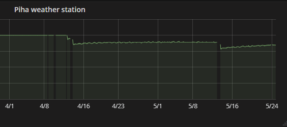
    Thought I would update this thread, still struggling but made some progress. I added the watchdog which helped somewhat, so far I have found a few things which I have fixed or investigated further on my efforts to make things more reliable. My gateway crashes after a few days - unsure why, suspect its a power issue so I have ordered a standalone 5v to 3.3v power supply to run the radio. My setup is a Wemos D1 mini. I am wary of changing too many things at once but I am considering wiring directly to a PI for a gateway. My side gate sensor used to drop off and come back after an hour or two. I noticed the TX was hovering around 90-100% so I thought it could be signal related, I built a mains powered repeater with the RFM69HW and placed it nearby. The side gate sensor favours the direct connection to the gateway but it seems to be more reliable. This sensor is a 1mhz/direct off the battery sensor. My BME280 sensor crashes a lot, I think this is related to the temp sensor rather than the node, seems to stop returning measurements except the battery voltage for a few hours then stops entirely. This is a sensor with a boost converter and when it crashes it never comes back, has to be reset. I am going try a different library for reading the BME280 when I get chance. I have also observed it gets less reliable as the battery voltage drops below 2.5v. Next up with annoying failures is my front gate sensor, previously most reliable it stopped working for 12hrs before magically reconnecting today, no reset required. It was rock solid till the battery voltage dropped to 2.5v, it's working now but I am going leave it to see if as the voltage drops the sensor becomes more unreliable. This sensor has plenty of signal strength to spare so I don't think the relay will help, its probably only 8m from the gateway. The boost converters I am using are the cheapest ones commonly available from china. To continue the experiment I have ordered some slightly more expensive ones to see if the performance changes. https://www.ebay.co.uk/itm/3-3V-5V-DC-DC-Boost-Converter-Step-up-Voltage-Regulator-Power-Supply-Module-New/272824785441?ssPageName=STRK%3AMEBIDX%3AIT&var=571970719316&_trksid=p2057872.m2749.l2649 I do have the capacitors in place, but am wondering if its worth experimenting with the values. People mentioned soldering/connectivity issues. I don't think thats my issue here. All my sensors are EasyPCB Rev9. Most of my sensors have no wires (ie no sensors, they're just testing their existence) or simple stuff like contact sensor or relay control This is the relay I made, its got a custom PCB under the sensor with a HLK-PM03, fuse, thermal fuse and a few other bits. Debmowsk designed the circuit originally I just rejigged it so it can be stacked on top of the easypcb rev9 [image: 1564601159633-5621520d-6a58-4ad8-8489-47330a480451-image-resized.png] [image: 1564601224965-8b25973e-adfe-4ee7-a41d-6a051811538a-image.png] [image: 1564601784969-2cd9261c-3180-4dd7-bc66-d435ec111c51-image-resized.png] [image: 1564601815122-ab5305a9-5ff6-4ced-8610-1d379e9410f0-image-resized.png] [image: 1564602211901-4c23f2b6-8983-40e9-a1b4-463ea3a74c2e-image-resized.png] [image: 1564605303138-fbe8123a-5190-4c06-a2a9-f9ea018fc828-image-resized.png] Far right of the graph shows the period the front gate sensor was offline for.
  • 0 Votes
    1 Posts
    208 Views
    No one has replied
  • Getting started with Wemos d1 mini & RFM69HW

    20
    0 Votes
    20 Posts
    1k Views
    L
    Yes D8 = pin 15 :) So any ideas on why the raspberry pi isn't sending parent information or "listening/responding" to the wemos? As a side sanity check I will try a different raspberry pi. Can someone confirm the pins on Pi2/3? Power - 1 Mosi -19 Miso -21 DIO - 22 Clk - 23 NSS - 24 GND - 25
  • 0 Votes
    9 Posts
    693 Views
    E
    Apparently this day is my lucky day :-) @scalz , you did me think with your comment about the samd21 board not triggering the irq. So I looked up where the pin layouts of all these 'arduino compatible' boards are defined. My used board is a RobotDyn Samd21 M0 board and they claim compatible with a Arduino M0 and I did use the Arduino SAMD boards (32-bits ARM Cortex-M0+) by Arduino version 1.8.3. The code you find at: https://github.com/arduino/ArduinoCore-samd With some help of the google doctor, I did find that the pin layouts are defined in the Variants.cpp file in https://github.com/arduino/ArduinoCore-samd/blob/master/variants/arduino_mzero/variant.cpp (I'm using the Arduino M0 entry when selecting my board) In this file /* * * + Pin number + ZERO Board pin | PIN | Label/Name | Comments (* is for default peripheral in use) * +------------+------------------+--------+-----------------+------------------------------ * | | Digital Low | | | * +------------+------------------+--------+-----------------+------------------------------ * | 0 | 0 -> RX | PA11 | | EIC/EXTINT[11] ADC/AIN[19] PTC/X[3] *SERCOM0/PAD[3] SERCOM2/PAD[3] TCC1/WO[1] TCC0/WO[3] * | 1 | 1 <- TX | PA10 | | EIC/EXTINT[10] ADC/AIN[18] PTC/X[2] *SERCOM0/PAD[2] TCC1/WO[0] TCC0/WO[2] * | 2 | ~2 | PA08 | | EIC/NMI ADC/AIN[16] PTC/X[0] SERCOM0/PAD[0] SERCOM2/PAD[0] *TCC0/WO[0] TCC1/WO[2] * | 3 | ~3 | PA09 | | EIC/EXTINT[9] ADC/AIN[17] PTC/X[1] SERCOM0/PAD[1] SERCOM2/PAD[1] *TCC0/WO[1] TCC1/WO[3] * | 4 | ~4 | PA14 | | EIC/EXTINT[14] SERCOM2/PAD[2] SERCOM4/PAD[2] TC3/WO[0] *TCC0/WO[4] * | 5 | ~5 | PA15 | | EIC/EXTINT[15] SERCOM2/PAD[3] SERCOM4/PAD[3] TC3/WO[1] *TCC0/WO[5] * | 6 | ~6 | PA20 | | EIC/EXTINT[4] PTC/X[8] SERCOM5/PAD[2] SERCOM3/PAD[2] TC7/WO[0] *TCC0/WO[6] * | 7 | ~7 | PA21 | | EIC/EXTINT[5] PTC/X[9] SERCOM5/PAD[3] SERCOM3/PAD[3] TC7/WO[1] *TCC0/WO[7] * +------------+------------------+--------+-----------------+------------------------------ * | | Digital High | | | * +------------+------------------+--------+-----------------+------------------------------ * | 8 | ~8 | PA06 | | EIC/EXTINT[6] PTC/Y[4] ADC/AIN[6] AC/AIN[2] SERCOM0/PAD[2] *TCC1/WO[0] * | 9 | ~9 | PA07 | | EIC/EXTINT[7] PTC/Y[5] DC/AIN[7] AC/AIN[3] SERCOM0/PAD[3] *TCC1/WO[1] * | 10 | ~10 | PA18 | | EIC/EXTINT[2] PTC/X[6] SERCOM1/PAD[2] SERCOM3/PAD[2] *TC3/WO[0] TCC0/WO[2] * | 11 | ~11 | PA16 | | EIC/EXTINT[0] PTC/X[4] SERCOM1/PAD[0] SERCOM3/PAD[0] *TCC2/WO[0] TCC0/WO[6] * | 12 | ~12 | PA19 | | EIC/EXTINT[3] PTC/X[7] SERCOM1/PAD[3] SERCOM3/PAD[3] *TC3/WO[1] TCC0/WO[3] * | 13 | ~13 | PA17 | LED | EIC/EXTINT[1] PTC/X[5] SERCOM1/PAD[1] SERCOM3/PAD[1] *TCC2/WO[1] TCC0/WO[7] * | 14 | GND | | | * | 15 | AREF | PA03 | | *DAC/VREFP PTC/Y[1] * | 16 | SDA | PA22 | | EIC/EXTINT[6] PTC/X[10] *SERCOM3/PAD[0] SERCOM5/PAD[0] TC4/WO[0] TCC0/WO[4] * | 17 | SCL | PA23 | | EIC/EXTINT[7] PTC/X[11] *SERCOM3/PAD[1] SERCOM5/PAD[1] TC4/WO[1] TCC0/WO[5] This is the defined pin mapping for a Arduino mZero. (I was using D2 as IRQ for the RFM69) * | 2 | ~2 | PA08 | But on the pin layout of the RobotDyn board I saw: * | 2 | ~2 | PA14 | On the RobotDyn the pin PA08 is mapped on the D4 arduino pin and not the D2 pin! With the pins D2/D4, RobotDyn is following here the Arduino Zero layout and NOT the Arduino mZero layout! So, I verified the other mappings and found that following pins are different mapped on the Arduino mZero: * | 2 | ~2 | PA08 | * | 4 | ~4 | PA14 | On the RobotDyn Samd21M0 * | 2 | ~2 | PA14 | * | 4 | ~4 | PA08 | So I changed the IRQ (DIO0) from the RF69 to the port D8 (PA06) and bingo it started to work :-) (did choose randomly D8) I saw also a difference in the SPI mapping mZero * | 18 | 1 | PA12 | MISO RobotDyn samd21 m0 * | not defined on their pin layout doc | 1 | PB12 | MISO But it is working, so maybe an error on RobotDyn's documentation? So if I resume the thing: The RobotDyn SAMD21 M0 board is claimed compatible with the Arduino M0 (mZero). In the IDE you must also select the Arduino M0. (selecting Arduino/Genuino Zero xxx will not work) But the RobotDyn used layout is compatible with the Arduino Zero, so pin D2 and D4 are reversed, making the code of the board Arduino M0 not working if you choose to use these pins in your design. So now we can continue to build our gateway, my originally goal. Edit : my MQTT gateway with the RobotDyn Samd21 M0 board, a W5500 ethernet module and a radio RFM69HW is up and running :-) Thanks for all comments that guided me to the solution :-)

18

Online

11.7k

Users

11.2k

Topics

113.1k

Posts