Custom power meter


  • I created a power meter based on emoncms. My code does not work quite correctly. When I run not everything is fine, but after reboot gets below the value of information and does not update.

    10-12-2014 12:02:57: 0;0;3;0;9;send: 0-0-6-6 s=255,c=3,t=8,pt=1,l=1,st=fail:0
    10-12-2014 12:02:56: 0;0;3;0;9;read: 6-6-255 s=255,c=3,t=7,pt=0,l=0:
    10-12-2014 12:02:36: 0;0;3;0;9;send: 0-0-6-6 s=255,c=3,t=8,pt=1,l=1,st=fail:0
    10-12-2014 12:02:36: 0;0;3;0;9;read: 6-6-255 s=255,c=3,t=7,pt=0,l=0:
    10-12-2014 12:02:16: 0;0;3;0;9;send: 0-0-6-6 s=255,c=3,t=8,pt=1,l=1,st=fail:0

    My sketch:. If i can improve code help me please

    // EmonLibrary examples openenergymonitor.org, Licence GNU GPL V3
     ***/
    #include <SPI.h>
    #include <MySensor.h>  
    #include "EmonLib.h"             // Include Emon Library
    EnergyMonitor emon1;             // Create an instance
    EnergyMonitor emon2;             // Create an instance
    EnergyMonitor emon3;             // Create an instance
    #define CHILD_ID 0  
    #define CHILD_ID2 1  
    #define CHILD_ID3 2  
    MySensor gw;
    unsigned long lastSend;
    unsigned long SEND_FREQUENCY = 20000; // Minimum time between send (in milliseconds). We don't wnat to spam the gateway.
    
    MyMessage realPowerMsg(CHILD_ID,V_VAR1);
    MyMessage apparentPowerMsg(CHILD_ID,V_VAR2);
    MyMessage powerFActorMsg(CHILD_ID,V_VAR3);
    MyMessage supplyVoltageMsg(CHILD_ID,V_VAR4);
    MyMessage IrmsMsg(CHILD_[link text](CHILD_ID,V_VAR5);
    
    MyMessage realPowerMsg2(CHILD_ID2,V_VAR1);
    MyMessage apparentPowerMsg2(CHILD_ID2,V_VAR2);
    MyMessage powerFActorMsg2(CHILD_ID2,V_VAR3);
    MyMessage supplyVoltageMsg2(CHILD_ID2,V_VAR4);
    MyMessage IrmsMsg2(CHILD_ID2,V_VAR5);
    
    MyMessage realPowerMsg3(CHILD_ID3,V_VAR1);
    MyMessage apparentPowerMsg3(CHILD_ID3,V_VAR2);
    MyMessage powerFActorMsg3(CHILD_ID3,V_VAR3);
    MyMessage supplyVoltageMsg3(CHILD_ID3,V_VAR4);
    MyMessage IrmsMsg3(CHILD_ID3,V_VAR5);
    
    
    void setup()
    {  
      gw.begin();
    
      // Send the sketch version information to the gateway and Controller
      gw.sendSketchInfo("Energy Meter x 3", "2.0");
    
      // Register this device as power sensor
      gw.present(CHILD_ID, S_POWER);
      gw.present(CHILD_ID2, S_POWER);
      gw.present(CHILD_ID3, S_POWER);
    
    
      emon1.voltage(A3, 116.26, 1.7);  // Voltage: input pin, calibration, phase_shift
      emon1.current(A0, 29.1);       // Current: input pin, calibration.
      emon2.voltage(A4, 116.76, 1.7);  // Voltage: input pin, calibration, phase_shift
      emon2.current(A1, 29.1);       // Current: input pin, calibration.
      emon3.voltage(A5, 116.46, 1.7);  // Voltage: input pin, calibration, phase_shift
      emon3.current(A2, 29.1);       // Current: input pin, calibration.
    }
    
    void loop()
    {
      gw.process();
      unsigned long now = millis();
      emon1.calcVI(20,2000);         // Calculate all. No.of half wavelengths (crossings), time-out
      //emon1.serialprint();           // Print out all variables (realpower, apparent power, Vrms, Irms, power factor)
      emon2.calcVI(20,2000);         // Calculate all. No.of half wavelengths (crossings), time-out
      //emon2.serialprint();           // Print out all variables (realpower, apparent power, Vrms, Irms, power factor)
      emon3.calcVI(20,2000);         // Calculate all. No.of half wavelengths (crossings), time-out
      //emon3.serialprint();           // Print out all variables (realpower, apparent power, Vrms, Irms, power factor)
      bool sendTime = now - lastSend > SEND_FREQUENCY;
      if (sendTime) { 
    
        float realPower       = emon1.realPower;        //extract Real Power into variable
        float apparentPower   = emon1.apparentPower;    //extract Apparent Power into variable
        float powerFactor     = emon1.powerFactor;      //extract Power Factor into Variable
        float supplyVoltage   = emon1.Vrms;             //extract Vrms into Variable
        float Irms            = emon1.Irms;             //extract Irms into Variable
        
        float realPower2       = emon2.realPower;        //extract Real Power into variable
        float apparentPower2   = emon2.apparentPower;    //extract Apparent Power into variable
        float powerFactor2     = emon2.powerFactor;      //extract Power Factor into Variable
        float supplyVoltage2   = emon2.Vrms;             //extract Vrms into Variable
        float Irms2            = emon2.Irms;             //extract Irms into Variable
        
        float realPower3       = emon3.realPower;        //extract Real Power into variable
        float apparentPower3   = emon3.apparentPower;    //extract Apparent Power into variable
        float powerFactor3     = emon3.powerFactor;      //extract Power Factor into Variable
        float supplyVoltage3   = emon3.Vrms;             //extract Vrms into Variable
        float Irms3            = emon3.Irms;             //extract Irms into Variable
    
        gw.send(realPowerMsg.set(realPower,1));
        gw.send(apparentPowerMsg.set(apparentPower,1));
        gw.send(powerFActorMsg.set(powerFactor,1));
        gw.send(supplyVoltageMsg.set(supplyVoltage,1));
        gw.send(IrmsMsg.set(Irms,1));
    
        gw.send(realPowerMsg2.set(realPower2,1));
        gw.send(apparentPowerMsg2.set(apparentPower2,1));
        gw.send(powerFActorMsg2.set(powerFactor2,1));
        gw.send(supplyVoltageMsg2.set(supplyVoltage2,1));
        gw.send(IrmsMsg2.set(Irms2,1));
    
        gw.send(realPowerMsg3.set(realPower3,1));
        gw.send(apparentPowerMsg3.set(apparentPower3,1));
        gw.send(powerFActorMsg3.set(powerFactor3,1));
        gw.send(supplyVoltageMsg3.set(supplyVoltage3,1));
        gw.send(IrmsMsg3.set(Irms3,1));
        
        lastSend = now;
      }
    
    }


  • I have emon energymonitor but trasmission is with RFM12B radio!!!

    emonTx_V2.0 overview_0.png


  • Hi, any progress with this? I would be interested in trying to adapt this to my needs. I have just finished setting up the basic arduino sketch from http://openenergymonitor.org/emon/buildingblocks/how-to-build-an-arduino-energy-monitor-measuring-current-only

    and i assume this should just work with the sketch you are working on?


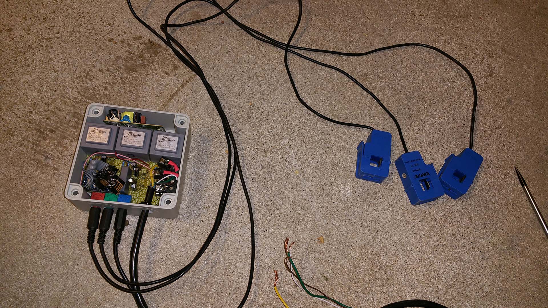
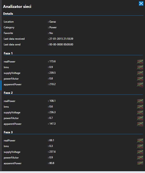
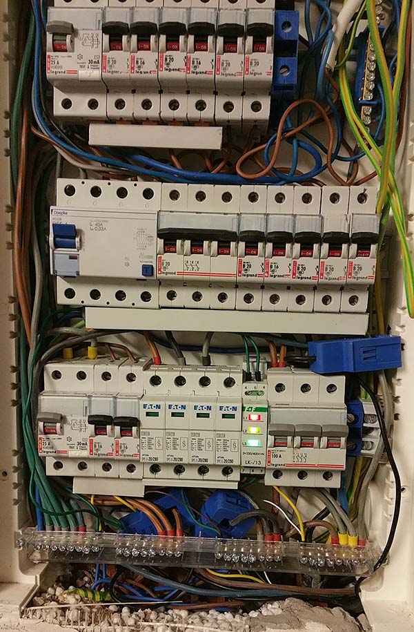
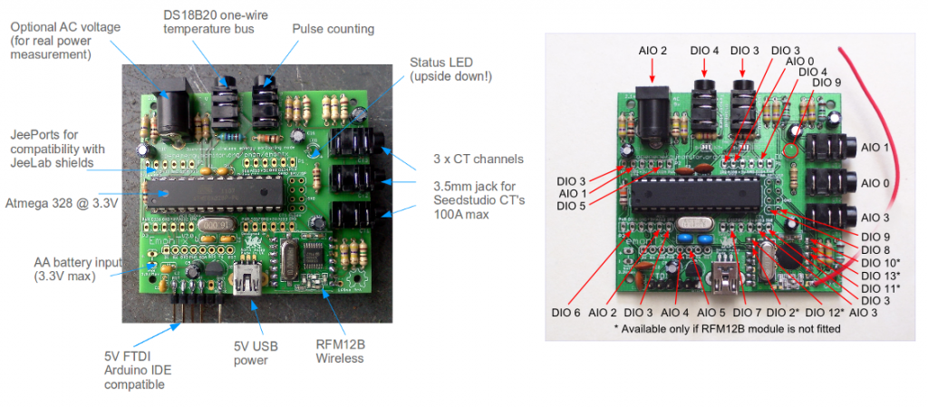
  • My hardware is on photo. I prepare hardware from emoncms site for 3 phases. My sketh working good so far about 3 weeks. My controler is pidome and send values to emoncms on mys NAS.

    20150123_214231.jpg
    obllcov.jpg
    ltbnanr.jpg
    20150125_191907.jpg


  • @maglo18
    Please put back the plastic cover πŸ™‚

    Looks good btw

    Boozz


  • Hero Member

    @maglo18 Is that 3 transformers in that box?


  • @ServiceXp In the box are 3 transformer, one for each phase to measure the voltage


  • @maglo18 How to transmit data to emoncms?


  • I use Pidome server and by automation rule send values to emoncms..


  • Hello,

    I've been looking in to this for quite some time. Here in the US, our residential wiring is usually 220V "split-phase" where we have a neutral/ground connection that allows us to get 120V from either "leg" (not to be confused with phase) to "ground". If you go "leg to leg", you'll get the full 220V of the phase.

    I've been searching quite a bit and am a little confused so I was hoping that you could expand on your solution a bit. (schematics, part numbers, full sketch) Your efforts look great. I'm wondering how you've integrated in to MySensors (and your controller, Vera?)

    In my case, I think that I will need to do the following:

    1. Have two CT's - one for each leg
    2. Have two transformers to measure each leg to neutral
    3. Somehow convert the voltage-measurement transformers in to something Arduino can read (0-5V)
    4. Convert the current induced by the CTs to a voltage that the Arduino can read
    5. Do the "V*I" math to calculate power, etc.

    Most US based solutions call for only one transformer/leg-measurement. However, I have seen an imbalance in my utility power. I'm not sure if this is due to underground resistance, faulty utility transformers, etc. But my point is, I think it'd be safer to measure both, do my calculations separately, and then add them accordingly (in software) to get total power consumption.

    Can you expand a bit on my thoughts? Has anyone in the US been successful in my above approach?


  • Hero Member

    @maglo18 why do you need a transformer ? my owl ones work on battery, couldn't that simplpify the sketch ?


  • I use transformer to measure voltage on each from three phases


  • @maglo18 how many is your burden resistor ?
    If found a blog where he talk about of turn in the sensor, do you know how many is it ?
    http://www.homautomation.org/2013/09/17/current-monitoring-with-non-invasive-sensor-and-arduino/


  • @maglo18

    please explain how to use one transformer on 3 phases to measure voltage on each


  • Hero Member

    @maglo18 said:

    I use transformer to measure voltage on each from three phases

    I have at home some OWL CM180i that work on batteries... how can it be applied to the example here ?


  • I use 3 x transformers One for each phase


  • @maglo18 said:

    I use 3 x transformers One for each phase

    Sorry for me it sounds like you use 1 transformer that was confusing me πŸ˜‰


  • Have anyone integrated this with Openhab? can we find somwhere some Openhab items, rules for this sketch that @maglo18 posted here http://forum.mysensors.org/topic/1464/sct-013-030-current-monitor-sensor?
    Thanks for any help!


  • Hi @maglo18 i have been using a current only version of emon for quite some time, i am interested in adding the ac-ac transformer to calculate the apparent power more accurately. Do you have a project page for your build with diagrams and specs? What type of transformers are you using (i can just about read it from picture) and how happy are you with the performance?

    Thanks Gambituk


  • Hi All,

    Did anyone worked with this sensor SCT-013-000 and Openhab? I would like to ask how can I integrate this with Openhab so to be able to display the apparent power consumption in watts, to display the Kwh starting a certain date lets say starting on 12th this month or from today as for example and to display to total Kwh.
    @maglo18 where are you from?

    Any help or suggestion will be kindly appreciated.

    Thanks All!


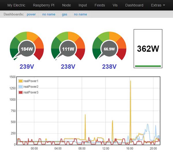
  • @GambitukI am very happy with performance. I'm logs power every 10s and voltage every 60s. It is sufficient. I built like on this site http://openenergymonitor.org/emon/buildingblocks/measuring-voltage-with-an-acac-power-adapter
    You can use transformer what you like but you must add voltage divider to have voltage max 2,5V on input in arduino if you use arduino 5V

    PS Poland/Warsaw


  • @maglo18 I saw some words in your pictures that looks familiar like faza or analizator πŸ™‚
    Can you share your latest Arduino sketch or if you have a complete tutorial about this project would be helpful.
    Thanks!


  • @maglo18: is the sketch in the first post your latest version? I would also like to do a very similar build and would like to get the best base πŸ™‚

    thanks!


  • This is my last and my final sketch

    #include <SPI.h>
    #include <MySensor.h>  
    #include "EmonLib.h"             // Include Emon Library
    EnergyMonitor emon1;             // Create an instance
    EnergyMonitor emon2;             // Create an instance
    EnergyMonitor emon3;             // Create an instance
    #define CHILD_ID 0  
    #define CHILD_ID2 1  
    #define CHILD_ID3 2  
    MySensor gw;
    unsigned long lastSend;
    unsigned long SEND_FREQUENCY = 10000; // Minimum time between send (in milliseconds). We don't wnat to spam the gateway.
    unsigned long lastSend2;
    unsigned long SEND_FREQUENCY2 = 300000; // Minimum time between send (in milliseconds). We don't wnat to spam the gateway.
    
    MyMessage realPowerMsg(CHILD_ID,V_VAR1);
    MyMessage apparentPowerMsg(CHILD_ID,V_VAR2);
    MyMessage powerFActorMsg(CHILD_ID,V_VAR3);
    MyMessage supplyVoltageMsg(CHILD_ID,V_VAR4);
    MyMessage IrmsMsg(CHILD_ID,V_VAR5);
    
    MyMessage realPowerMsg2(CHILD_ID2,V_VAR1);
    MyMessage apparentPowerMsg2(CHILD_ID2,V_VAR2);
    MyMessage powerFActorMsg2(CHILD_ID2,V_VAR3);
    MyMessage supplyVoltageMsg2(CHILD_ID2,V_VAR4);
    MyMessage IrmsMsg2(CHILD_ID2,V_VAR5);
    
    MyMessage realPowerMsg3(CHILD_ID3,V_VAR1);
    MyMessage apparentPowerMsg3(CHILD_ID3,V_VAR2);
    MyMessage powerFActorMsg3(CHILD_ID3,V_VAR3);
    MyMessage supplyVoltageMsg3(CHILD_ID3,V_VAR4);
    MyMessage IrmsMsg3(CHILD_ID3,V_VAR5);
    
    void setup()
    {  
      gw.begin(NULL, 4, false, 0);
      Serial.begin(115200); // opens serial port, sets data rate to 9600 bps
      // Send the sketch version information to the gateway and Controller
      gw.sendSketchInfo("Energy Meter x 3v2", "1.2");
      // Register this device as power sensor
      gw.present(CHILD_ID, S_POWER);
      gw.present(CHILD_ID2, S_POWER);
      gw.present(CHILD_ID3, S_POWER);
    
      emon1.voltage(A3, 116.26, 1.7);  // Voltage: input pin, calibration, phase_shift
      emon1.current(A0, 29.0);       // Current: input pin, calibration.
      emon2.voltage(A4, 116.66, 1.7);  // Voltage: input pin, calibration, phase_shift
      emon2.current(A1, 29.0);       // Current: input pin, calibration.
      emon3.voltage(A5, 115.91, 1.7);  // Voltage: input pin, calibration, phase_shift
      emon3.current(A2, 29.0);       // Current: input pin, calibration.
    }
    
    void loop()
    {
      gw.process();
      unsigned long now = millis();
      emon1.calcVI(20,2000);         // Calculate all. No.of half wavelengths (crossings), time-out
      //emon1.serialprint();           // Print out all variables (realpower, apparent power, Vrms, Irms, power factor)
      emon2.calcVI(20,2000);         // Calculate all. No.of half wavelengths (crossings), time-out
      //emon2.serialprint();           // Print out all variables (realpower, apparent power, Vrms, Irms, power factor)
      emon3.calcVI(20,2000);         // Calculate all. No.of half wavelengths (crossings), time-out
      //emon3.serialprint();           // Print out all variables (realpower, apparent power, Vrms, Irms, power factor)
    
      bool sendTime = now - lastSend > SEND_FREQUENCY;
      if (sendTime) { 
    
        float realPower       = emon1.realPower;        //extract Real Power into variable
        float realPower2       = emon2.realPower;        //extract Real Power into variable
        float realPower3       = emon3.realPower;        //extract Real Power into variable
    
        if(realPower > 0 && realPower < 10000){
        gw.send(realPowerMsg.set(realPower,1));
        }
        if(realPower2 > 0 && realPower2 < 10000){
        gw.send(realPowerMsg2.set(realPower2,1));
        }
        if(realPower3 > 0 && realPower3 < 10000){
        gw.send(realPowerMsg3.set(realPower3,1));
        }
        lastSend = now;
      }
    
      bool sendTime2 = now - lastSend2 > SEND_FREQUENCY2;
      if(sendTime2){
    
        float apparentPower   = emon1.apparentPower;    //extract Apparent Power into variable
        float powerFactor     = emon1.powerFactor;      //extract Power Factor into Variable
        float supplyVoltage   = emon1.Vrms;             //extract Vrms into Variable
        float Irms            = emon1.Irms;             //extract Irms into Variable
        
        float apparentPower2   = emon2.apparentPower;    //extract Apparent Power into variable
        float powerFactor2     = emon2.powerFactor;      //extract Power Factor into Variable
        float supplyVoltage2   = emon2.Vrms;             //extract Vrms into Variable
        float Irms2            = emon2.Irms;             //extract Irms into Variable
        
        float apparentPower3   = emon3.apparentPower;    //extract Apparent Power into variable
        float powerFactor3     = emon3.powerFactor;      //extract Power Factor into Variable
        float supplyVoltage3   = emon3.Vrms;             //extract Vrms into Variable
        float Irms3            = emon3.Irms;             //extract Irms into Variable
    
    
        if(apparentPower > 0 && apparentPower < 10000){
        gw.send(apparentPowerMsg.set(apparentPower,1));
        }
        if(powerFactor > 0 && powerFactor < 10000){
        gw.send(powerFActorMsg.set(powerFactor,1));
        }
        if(supplyVoltage > 0 && supplyVoltage < 1000){
        gw.send(supplyVoltageMsg.set(supplyVoltage,1));
        }
        if(Irms > 0 && Irms < 1000){   
        gw.send(IrmsMsg.set(Irms,1));
        }
    
        if(apparentPower2 > 0 && apparentPower2 < 10000){
        gw.send(apparentPowerMsg2.set(apparentPower2,1));
        }
        if(powerFactor2 > 0 && powerFactor2 < 10000){
        gw.send(powerFActorMsg2.set(powerFactor2,1));
        }
        if(supplyVoltage2 > 0 && supplyVoltage2 < 1000){
        gw.send(supplyVoltageMsg2.set(supplyVoltage2,1));
        }
        if(Irms2 > 0 && Irms2 < 1000){   
        gw.send(IrmsMsg2.set(Irms2,1));
        }
    
        if(apparentPower3 > 0 && apparentPower3 < 10000){
        gw.send(apparentPowerMsg3.set(apparentPower3,1));
        }
        if(powerFactor3 > 0 && powerFactor3 < 10000){
        gw.send(powerFActorMsg3.set(powerFactor3,1));
        }
        if(supplyVoltage3 > 0 && supplyVoltage3 < 1000){
        gw.send(supplyVoltageMsg3.set(supplyVoltage3,1));
        }
        if(Irms3 > 0 && Irms3 < 1000){   
        gw.send(IrmsMsg3.set(Irms3,1));
        }
        lastSend2 = now;
      }
    }


  • Thank you for sharing this code.
    I modified your code only for a CT sensor which is connected to A0. The CT is connected to a 40 Watts lamp and this is what i get on Arduino serial monitor:

    sensor started, id 4
    send: 4-4-0-0 s=255,c=0,t=17,pt=0,l=5,st=ok:1.4.1
    send: 4-4-0-0 s=255,c=3,t=6,pt=1,l=1,st=ok:0
    send: 4-4-0-0 s=255,c=3,t=11,pt=0,l=18,st=ok:Energy Meter x 3v2
    send: 4-4-0-0 s=255,c=3,t=12,pt=0,l=3,st=ok:1.2
    send: 4-4-0-0 s=0,c=0,t=13,pt=0,l=0,st=ok:
    send: 4-4-0-0 s=0,c=1,t=24,pt=7,l=5,st=ok:0.1
    

    what is the last value (0.1)? Amps? if i turn off the lamp the i get 0.0!
    In your sketch i see you calculate the real power, power factor, Vrms (volts?) and Irms (Amps?)

        float apparentPower   = emon1.apparentPower;    //extract Apparent Power into variable
        float powerFactor     = emon1.powerFactor;      //extract Power Factor into Variable
        float supplyVoltage   = emon1.Vrms;             //extract Vrms into Variable
        float Irms            = emon1.Irms;             //extract Irms into Variable
    

    why is displaying in the serial monitor only one value which i assume is Irms?

    I would like to calculate only the power and to export this to openhab but.....i dont know how 😞


  • @maglo18
    Hello,
    I have a question about your sensor
    I want to do a similar sensor, with 3 or more Amp meter but just one voltage.
    Is it possible ( or a bad idear) to use transformer for measuring voltage and use as power suply (with regulation 5v and 3,3v) for sensor?

    Thank's


  • You can use one voltage and use few Amps but only on one phase . If you want to measure Amps on other phases you should add another voltage meter on each phases.
    You can't to use transformer for power supply because on transformer for measuring is AC voltage and power supply for arduino is DC voltage


  • For precision, I've just one phase at home, but I want few Amps meter for different "sectors" of the house.
    My question was: Is it a good idea to use the transformer (I've a AC 220V to AC 12v 3VA) for both using: power supply of the sensor (with rectifier bridge and capacity and regulator) and for voltage meter (with divider bridge as you do in your sensor).
    Or it's a bad idear: Is it possible, in this configuration, to generate a voltage variation when arduino send informations?


  • Where do I get the calibration of a SCT-013-000 from. I found this description https://openenergymonitor.org/emon/buildingblocks/ct-and-ac-power-adaptor-installation-and-calibration-theory but unfortunately, I've no idea how to measure the correct calibration.
    As far as I understand this article, there could be a total error of 19.5% in uncalibrated case.
    Can anybody help an non-electrician πŸ˜‰


  • @maglo18
    Help me please, I have a SCT 013-000 sensor but i do not have python program code. I want to use these sensors to measure electric current power. The sensor is connected with raspberry pi.


Log in to reply
 

Suggested Topics

  • 3
  • 2
  • 2
  • 2
  • 3
  • 15

0
Online

11.2k
Users

11.1k
Topics

112.5k
Posts