MQTT Gateway - Stuck on "Started!"
-
@siod I am using the W5100 Ethernet module so there is no need to change the library. Funny thing...I just compiled bot MQTT and Ethernet GW without any problems. They seem to work and I finally can ping them.:bowtie:
The only thing that I changed is that now I use an official Arduino UNO and not the pro minis. I will try the circuit with the mini again and I will update my post.
-
W5100, sure, should have read your first post again. No need for the UIPEthernet library, of course.
Ok, thanks for the hint, as I am using a nano testing with an uno could be an option. Will wait for your updated post first...
@siod I tried again with an unofficial Arduino UNO R3. None of the gateways is working. I get the same symptoms with the pro minis (which are also unofficial boards from China).
- Could someone comment of the official/unofficial board issue?
- I suppose it could be useful to start a compatibility list for the gateways.
UPDATE: I attach a picture with the two boards that do not work correctly with the Ethernet and the MQTT gateway sketch. I managed to compile and upload the sketches to the boards without any problem. In the serial monitor I get the proper message showing that the GW has started, however I cannot ping it.
UPDATE 2: I removed the photos that I have posted earlier since all the boards seem to work correctly. See post below.
-
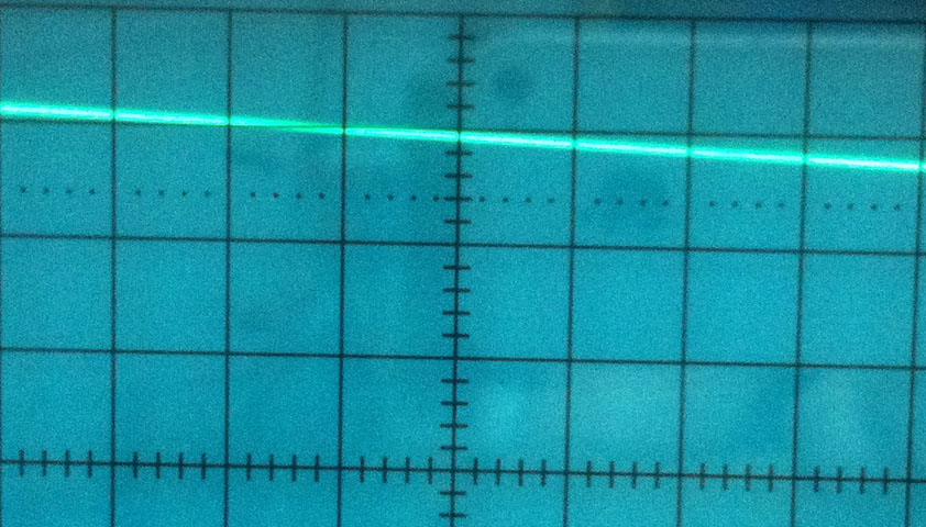
@hek I am pretty sure that this is not the case. I have a quite decent power supply. Attached is a picture of my stone age 10MHz oscilloscope. Although old with some tilt issues (I have to fix that) it is quite enough for identifying a poor power supply. As you can see there are no decoupling issues.
UPDATE: Finally, after experimenting for more than a week, the gateway seems to work even with the unofficial Arduino boards! Unfortunately I don't know what the problem was. I would blame the power supply but the gw now works with all boards and with three different power supplies (bench power supply, PC usb port and cell phone chargers), including those (cell charger, desktop usb port and laptop usb port) I was using before.
In case i find what the problem was I will post it here. Of course I now have to get the gw working with one of the software controllers, probably with Domoticz.
Thanks for your contributions!
-
mmh, that´s very strange. Did you change anything in your code? I can´t test right now but will give you more info the next days.
-
Uploaded sketch on my original Arduino Uno, made same connections, did not change anything in the code:
- Serial Monitor is showing nothing -.-
edit: can I use an Uno using the same code for the nano? :suspect:
edit2: Testing Nano again. Unconnected Ethernet module from nano, still only geting "Started!" message. Uploaded Ethernet Gateway Sketch and everything is fine again. -> So it must have to do sth. with the code. :hurtrealbad:
edit3: Now tested different nanos, still the same problem with every Nano. Holy, I don´t have any more ideas...:finnadie:edit4: I shit bricks...I downloaded the whole MySensors Library again, installed it and uploaded the sketch again: IT WORKS ! ! ! :feelsgood:
Some file must have been missing...WTF. Well, thanks anyway guys, have fun with your sensors. :godmode: -
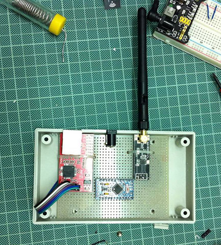
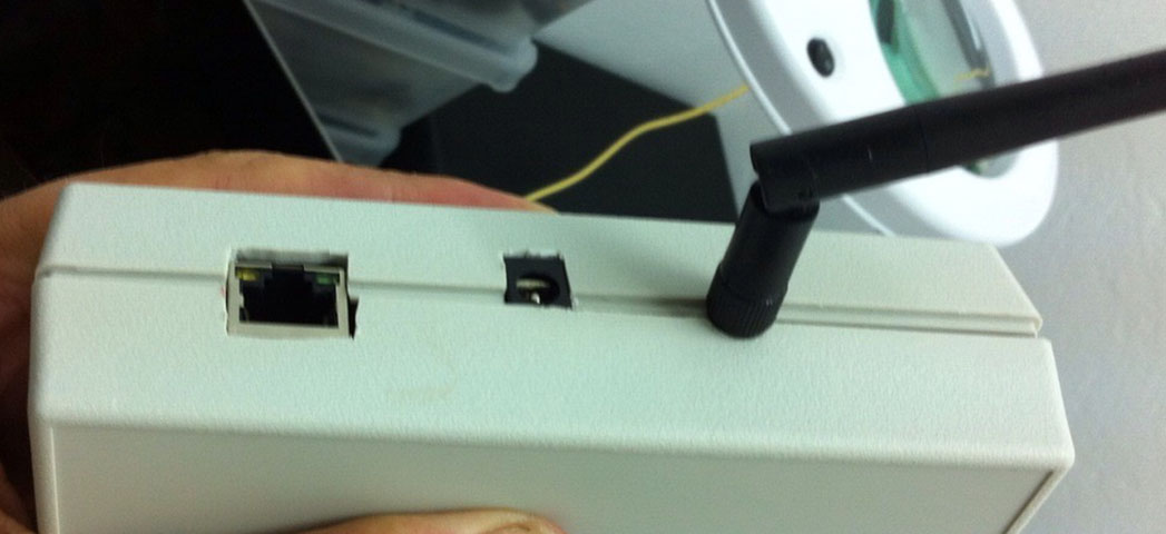
Not as tidy as other gateways, yet its something. I got bored and didn't open holes for LEDs. I'll do it after I am sure that it works. For the moment I am able to ping it successfully. I am thinking now that an Arduino nano is more appropriate for a GW. The USB port can be used to monitor and reflash the gateway.
PS. I am pretty sure now that the power supply was the problem. The AC to DC unit that I was using (12V) could provide just 0.5 Amps an probably this is not enough for all the components to work properly. Has anyone measured what is the max current required from such a GW?
-
@Zed , the antenna-version of nRF officially consumes up to 115mA (cheap clones can easily drawn more). The w5100 running at 100Mbps may consume ~140mA. That still leave some room for your arduino. Have you measured the DC adapter with full load on it?
-
@Zed , the antenna-version of nRF officially consumes up to 115mA (cheap clones can easily drawn more). The w5100 running at 100Mbps may consume ~140mA. That still leave some room for your arduino. Have you measured the DC adapter with full load on it?
@rvendrame No, I have not measured the DC adapter with full load on it. I will do it in the following days and I will report my findings.
-
I still have some trouble... Although this seems like a Domoticz question, I'll post it here because I think that the problem is related to my Ethernet GW and not to Domoticz.
So, I upgraded my GW to mySensors 1.5 and I made a Temperature/Humidity sensor as it is described here using a DHT22. On the serial monitor I get:
find parent
send: 255-255-255-255 s=255,c=3,t=7,pt=0,l=0,sg=0,st=bc:
sensor started, id=255, parent=255, distance=255
find parent
send: 255-255-255-255 s=255,c=3,t=7,pt=0,l=0,sg=0,st=bc:
find parent
send: 255-255-255-255 s=255,c=3,t=7,pt=0,l=0,sg=0,st=bc:
find parent
send: 255-255-255-255 s=255,c=3,t=7,pt=0,l=0,sg=0,st=bc:
find parent
send: 255-255-255-255 s=255,c=3,t=7,pt=0,l=0,sg=0,st=bc:
find parent
send: 255-255-255-255 s=255,c=3,t=7,pt=0,l=0,sg=0,st=bc:
T: 31.00
find parent
send: 255-255-255-255 s=255,c=3,t=7,pt=0,l=0,sg=0,st=bc:
H: 44.40
I don't really understand the message (could someone explain a little bit), however I suppose that the sensor works. Then, on the serial monitor of the ethernet gateway I get:
0;0;3;0;9;gateway started, id=0, parent=0, distance=0On Domoticz I have added the Ethernet GW to the hardware list. However when I open the web interface i see the following:
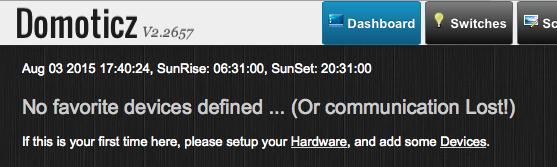
and in the log I get:
2015-08-03 17:03:45.650 Domoticz V2.2657 (c)2012-2015 GizMoCuz
2015-08-03 17:03:45.758 Sunrise: 06:31:00 SunSet:20:31:00
2015-08-03 17:03:45.763 Active notification subsystems: (0/8)
2015-08-03 17:03:46.164 Webserver started on port: 8008
2015-08-03 17:03:46.171 Webserver started on port: 443
2015-08-03 17:03:46.172 Hardware Monitor: Started
2015-08-03 17:03:48.509 Incoming connection from: 127.0.0.1
2015-08-03 17:03:49.837 Incoming connection from: 192.168.1.14
2015-08-03 17:03:50.191 MySensors: connected to: 192.168.1.152:5003
Questions:
- Does the GW message mean that the GW is not working properly?
- I've set the IP of the GW to be 192.168.1.152 and Port 5003. Does this mean that the same port has to be free on the server side?
- What is the inclusion button. Do I have to add it to the GW?
So, any suggestions for troubleshooting? :bowtie:
PS: Configuration summary
Arduino IDE: 1.6.5
OS: Mac OS X Yosemite 10.10.4 (for the sketches) and Windows 10 for Domoticz
MySensor Library: 1.5 -
Looks like GW has started correctly but no messages seems to reach the gateway from the node. The node is broadcasting a find-parent-request with no answer from the gateway.
Hard to say what the problem is.. Have you changed any channels settings in MyConfig.h before compiling gateway/node?
-
Looks like GW has started correctly but no messages seems to reach the gateway from the node. The node is broadcasting a find-parent-request with no answer from the gateway.
Hard to say what the problem is.. Have you changed any channels settings in MyConfig.h before compiling gateway/node?
@hek No, I didn't change anything. Should I?
I am experimenting now with MYSController. I send a version request to the gateway and I get a proper reply.
8/3/2015 20:18:04	TX	0;0;3;0;2;
8/3/2015 20:18:04	RX	0;0;3;0;2;1.5
(If I ask for the sketch name or version I do not get a reply)
I am suspecting that the radio module of the gateway may not work properly. Is there a way to check this without de-soldering the module and replacing it by another one?
-
I still have some trouble... Although this seems like a Domoticz question, I'll post it here because I think that the problem is related to my Ethernet GW and not to Domoticz.
So, I upgraded my GW to mySensors 1.5 and I made a Temperature/Humidity sensor as it is described here using a DHT22. On the serial monitor I get:
find parent
send: 255-255-255-255 s=255,c=3,t=7,pt=0,l=0,sg=0,st=bc:
sensor started, id=255, parent=255, distance=255
find parent
send: 255-255-255-255 s=255,c=3,t=7,pt=0,l=0,sg=0,st=bc:
find parent
send: 255-255-255-255 s=255,c=3,t=7,pt=0,l=0,sg=0,st=bc:
find parent
send: 255-255-255-255 s=255,c=3,t=7,pt=0,l=0,sg=0,st=bc:
find parent
send: 255-255-255-255 s=255,c=3,t=7,pt=0,l=0,sg=0,st=bc:
find parent
send: 255-255-255-255 s=255,c=3,t=7,pt=0,l=0,sg=0,st=bc:
T: 31.00
find parent
send: 255-255-255-255 s=255,c=3,t=7,pt=0,l=0,sg=0,st=bc:
H: 44.40
I don't really understand the message (could someone explain a little bit), however I suppose that the sensor works. Then, on the serial monitor of the ethernet gateway I get:
0;0;3;0;9;gateway started, id=0, parent=0, distance=0On Domoticz I have added the Ethernet GW to the hardware list. However when I open the web interface i see the following:
and in the log I get:
2015-08-03 17:03:45.650 Domoticz V2.2657 (c)2012-2015 GizMoCuz
2015-08-03 17:03:45.758 Sunrise: 06:31:00 SunSet:20:31:00
2015-08-03 17:03:45.763 Active notification subsystems: (0/8)
2015-08-03 17:03:46.164 Webserver started on port: 8008
2015-08-03 17:03:46.171 Webserver started on port: 443
2015-08-03 17:03:46.172 Hardware Monitor: Started
2015-08-03 17:03:48.509 Incoming connection from: 127.0.0.1
2015-08-03 17:03:49.837 Incoming connection from: 192.168.1.14
2015-08-03 17:03:50.191 MySensors: connected to: 192.168.1.152:5003
Questions:
- Does the GW message mean that the GW is not working properly?
- I've set the IP of the GW to be 192.168.1.152 and Port 5003. Does this mean that the same port has to be free on the server side?
- What is the inclusion button. Do I have to add it to the GW?
So, any suggestions for troubleshooting? :bowtie:
PS: Configuration summary
Arduino IDE: 1.6.5
OS: Mac OS X Yosemite 10.10.4 (for the sketches) and Windows 10 for Domoticz
MySensor Library: 1.5 -
You might have the same problem described here:
http://forum.mysensors.org/topic/1736/release-1-5-and-ethernet-gatewaySeems like you have to send something from gateway before you can receive anything.. A bug.
@hek Probably this is not the case. I downgraded everything to 1.4.1. Now on the sensor serial monitor I get:
req node id
send: 255-255-255-0 s=255,c=3,t=3,pt=0,l=0,st=fail:
req node id
send: 255-255-255-0 s=255,c=3,t=3,pt=0,l=0,st=fail:
req node id
send: 255-255-255-0 s=255,c=3,t=3,pt=0,l=0,st=fail:
req node id
send: 255-255-255-0 s=255,c=3,t=3,pt=0,l=0,st=fail:
T: 31.30
req node id
send: 255-255-255-0 s=255,c=3,t=3,pt=0,l=0,st=fail:
send: 255-255-255-255 s=255,c=3,t=7,pt=0,l=0,st=fail:
H: 38.50
req node id
send: 255-255-255-0 s=255,c=3,t=3,pt=0,l=0,st=fail:
T: 31.20
req node id
send: 255-255-255-0 s=255,c=3,t=3,pt=0,l=0,st=fail:
H: 39.70
If understand it correctly the sensor still is not able to get an ID from the GW. Probably I will make a serial gateway in the following days for testing.
-
Sorry @Zed, replied to the wrong post. (Tip! Don't have too many forum windows open at the same time)
Everything works now. I made another Ethernet gateway using an Arduino Uno, a compatible Ethernet Shield and a RF24L01+ module without the antenna. Now the sensors get their reply from the gateway and they report to Domoticz seamlessly.
It seems that the problem was with the antenna version RF24L01+ module I was using. Probably it got destroyed when I replaced its pins.
Some guidelines for troubleshooting that may help others:
- check that the power supply is good enough. If you are using one of these cheap breadboard power supplies with the ams1117 regulators, check that you provide enough voltage for the regulators to work properly. Do not expect from a capacitor to save you from a faulty power supply, especial when you use batteries. Have in mind that some of these supplies are shipped with faulty regulators and provide as high voltage as their input.
- verify that the Ethernet module works properly. Just upload a simple sketch and get an IP. eg. test this.
- verify that the nrf24 modules work properly. You can try this. Actually a test circuit to check the RF modules before using them may save you a lot of time.
- Get the latest mySensor sketches from github.
- Use MYScontroller to monitor the messages the getway and the sensors exchange.
Hello! It looks like you're interested in this conversation, but you don't have an account yet.
Getting fed up of having to scroll through the same posts each visit? When you register for an account, you'll always come back to exactly where you were before, and choose to be notified of new replies (either via email, or push notification). You'll also be able to save bookmarks and upvote posts to show your appreciation to other community members.
With your input, this post could be even better 💗
Register Login