PhoneyTV for Vera is Here!
-
So here is a fun project for you to build... introducing PhoneyTV for Vera.
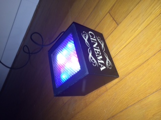
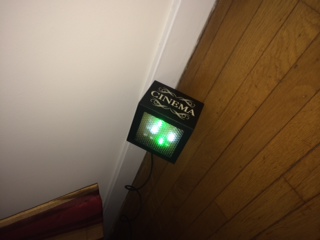
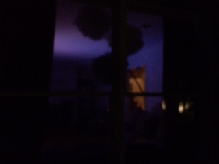
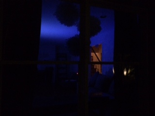
PhoneyTV is a Home Automation connected security device that mimics the ambient light produced by a television. This makes your house appear to be occupied and will hopefully deter would-be robbers from trying to enter your house.
Some highlights:
- Utilizes the MySensors basic sketch for relays, therefore controllable by Vera.
Energy efficient versus actually leaving a TV on. My 12x 1/2watt LEDs are burning average of about 5 watts with the PWM... a nightlight basically.
It I can be BRIGHT with 12 10mm LED's produces the light of a 50in LCD TV, in my observation.
Utilizes 6 channels featuring 3 PWM pins in order to vary the intensity of blues and whites.
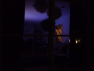
Uses no Delays, rather it uses a timer to produce its random flickering while maintaining terrific radio connection.
Is customizable to allow you to adjust your PhoneyTV to behave to your specific preferences.
Is EASY to make... It can be 100% powered by your Arduino and with exception of the actual LED's (I used 12pcs of 1/2watt super-bright 10mm LED's) only requires a board and a few resistors (be careful with this red LEDs).
It can be powered with an old cell phone charger or any 7-12V power supply.
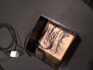
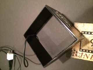
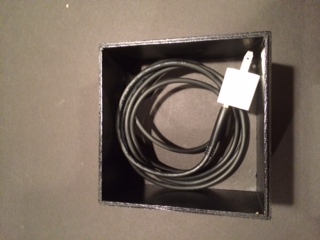
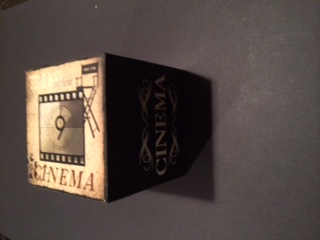
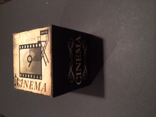
You can create a custom, fun housing to camouflage or highlight your PhoneyTV. I repurposed a box that has been sitting on a shelf empty for a while. It is nice because when it is not in use, it can be invisible.
You can breadboard it on your UNO in under 45 minutes and depending on your box, build in in one evening.
It can be improved... While this produces a pretty realistic effect, nothing is preventing you from adding more to it like dimming or even multiplexing.
It is inexpensive versus buying something like FakeTV, where after $30, you will still have to add Home Automation ready outlet if you want to control it. I used a Nano, but you could try a ProMini and save a few bucks.
Is expandable. Why not add a Thermometer, Hygrometer or Barometer? For a few more dollars you can monitor the room you keep your Phoney TV in.
I have attached some photos of the approach I took to build the physical box, of course there are many possibilities for you to consider and build.
I'll post the sketch in an update...
I want to give credit to DeltaNu1142 for the inspiration and the idea, thanks!
- Utilizes the MySensors basic sketch for relays, therefore controllable by Vera.
-
So here is a fun project for you to build... introducing PhoneyTV for Vera.
PhoneyTV is a Home Automation connected security device that mimics the ambient light produced by a television. This makes your house appear to be occupied and will hopefully deter would-be robbers from trying to enter your house.
Some highlights:
- Utilizes the MySensors basic sketch for relays, therefore controllable by Vera.
Energy efficient versus actually leaving a TV on. My 12x 1/2watt LEDs are burning average of about 5 watts with the PWM... a nightlight basically.
It I can be BRIGHT with 12 10mm LED's produces the light of a 50in LCD TV, in my observation.
Utilizes 6 channels featuring 3 PWM pins in order to vary the intensity of blues and whites.
Uses no Delays, rather it uses a timer to produce its random flickering while maintaining terrific radio connection.
Is customizable to allow you to adjust your PhoneyTV to behave to your specific preferences.
Is EASY to make... It can be 100% powered by your Arduino and with exception of the actual LED's (I used 12pcs of 1/2watt super-bright 10mm LED's) only requires a board and a few resistors (be careful with this red LEDs).
It can be powered with an old cell phone charger or any 7-12V power supply.
You can create a custom, fun housing to camouflage or highlight your PhoneyTV. I repurposed a box that has been sitting on a shelf empty for a while. It is nice because when it is not in use, it can be invisible.
You can breadboard it on your UNO in under 45 minutes and depending on your box, build in in one evening.
It can be improved... While this produces a pretty realistic effect, nothing is preventing you from adding more to it like dimming or even multiplexing.
It is inexpensive versus buying something like FakeTV, where after $30, you will still have to add Home Automation ready outlet if you want to control it. I used a Nano, but you could try a ProMini and save a few bucks.
Is expandable. Why not add a Thermometer, Hygrometer or Barometer? For a few more dollars you can monitor the room you keep your Phoney TV in.
I have attached some photos of the approach I took to build the physical box, of course there are many possibilities for you to consider and build.
I'll post the sketch in an update...
I want to give credit to DeltaNu1142 for the inspiration and the idea, thanks!
The Sketch:
the Schematic...
So simple, there is no reason not to try it!
There is an UPDATED Version below, which adds a momentary pushbutton switch to control it locally. (software debounce)
- Utilizes the MySensors basic sketch for relays, therefore controllable by Vera.
-
Hi @BulldogLowell,
This looks exactly like something I need in a a couple of weeks :)
The pdf says 1:4 but I see only page 1.
-
Hi @BulldogLowell,
This looks exactly like something I need in a a couple of weeks :)
The pdf says 1:4 but I see only page 1.
The other pages are from the schematic diagraming software for BOM, etc, but I didn't fill out the lists so they are blank pages.
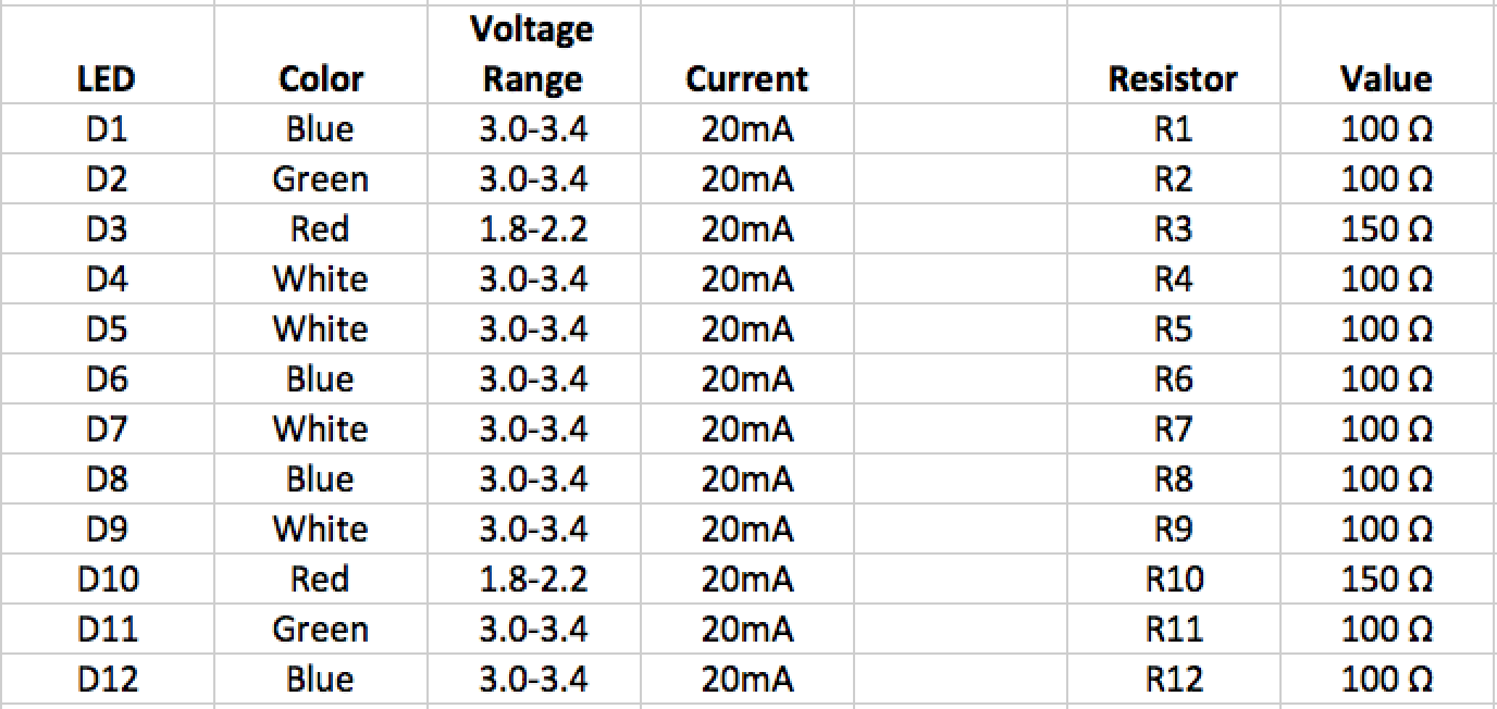
Te resistor values depend on the LED's you choose but I used these. and chose to do the diffusing cover. If you buy diffused LED's you may get better results if you use a clear or frosted diffuser/cover.
Besides the arduino and the radio, here are the resistor values, the pinouts are in the sketch as far as the colours.
-
Really nice! Thanks....
-
I followed your instructions and built a PhoneyTV this weekend. Great success!
This was the first time I used a prototype board to build something and it wasn't really that difficult. If there is some other beginner out there who's thinking about building this project, I say go for it.While I was at it I put a DHT22 on the board, maybe I'll substitute it for a Dallas DS18B20 to cut cost.
Good thinking on the Dallas sensor. I just ordered a few and am looking forward to adding them here and there as I build more stuff.
And soldering isn't too bad, yeah?
-
The Sketch:
the Schematic...
So simple, there is no reason not to try it!
There is an UPDATED Version below, which adds a momentary pushbutton switch to control it locally. (software debounce)
Hi
Im a bit confused about the J1 in the schematic... It seems you dont use it or i dont understand what it is :-)
But how is the diodes then connected to the board?Regards
Jan -
Hi
Im a bit confused about the J1 in the schematic... It seems you dont use it or i dont understand what it is :-)
But how is the diodes then connected to the board?Regards
Jan@stofakiller said:
Hi
Im a bit confused about the J1 in the schematic... It seems you dont use it or i dont understand what it is :-)
But how is the diodes then connected to the board?Regards
JanJan,
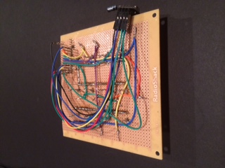
the LEDs I used are through-hole pins; I soldered them to the board. The photo shows their respective resistors connected to them accordingly. I soldered a trace to connect all of the cathodes to ground, put the resistors in series with the anodes. PIN>>RESISTOR>>ANODE.
As far as the connector numbers go, use the MySensors standard radio connection and the pinouts for the LEDs detailed in the sketch. In my experience, having the Blue and White on some PWM gives a more realistic effect. The numbers don't match the Nano because I used the header component in the software I used to create the circuit diagram.
good luck why your build!
-
@stofakiller said:
Hi
Im a bit confused about the J1 in the schematic... It seems you dont use it or i dont understand what it is :-)
But how is the diodes then connected to the board?Regards
JanJan,
the LEDs I used are through-hole pins; I soldered them to the board. The photo shows their respective resistors connected to them accordingly. I soldered a trace to connect all of the cathodes to ground, put the resistors in series with the anodes. PIN>>RESISTOR>>ANODE.
As far as the connector numbers go, use the MySensors standard radio connection and the pinouts for the LEDs detailed in the sketch. In my experience, having the Blue and White on some PWM gives a more realistic effect. The numbers don't match the Nano because I used the header component in the software I used to create the circuit diagram.
good luck why your build!
Okay, now i better understand, because in the schematics the J1 is connected to pin 3 and i didnt get it to work, but also the D1 you use is Blue, but in the sketch the first one you use is white ;-) So now i got the 6 diodes connected, what about the other 6? :-) are the connected parallel? (whites, red greens etc)
Regards Jan
-
Okay, now i better understand, because in the schematics the J1 is connected to pin 3 and i didnt get it to work, but also the D1 you use is Blue, but in the sketch the first one you use is white ;-) So now i got the 6 diodes connected, what about the other 6? :-) are the connected parallel? (whites, red greens etc)
Regards Jan
@stofakiller said:
Okay, now i better understand, because in the schematics the J1 is connected to pin 3 and i didnt get it to work, but also the D1 you use is Blue, but in the sketch the first one you use is white ;-) So now i got the 6 diodes connected, what about the other 6? :-) are the connected parallel? (whites, red greens etc)
Regards Jan
Sorry about the schematic, I actually recall thinking that would come back to haunt me. I'll fix it to make it easier for the next guy :)
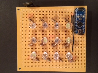
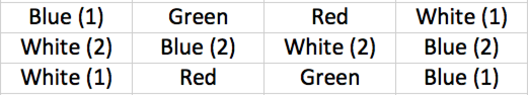
Yes, I put two LEDs on each 'channel' wired in parallel. This way, you can power all 12 LEDs with the arduino, no problem.
Six channels with two LEDs each.
Blue1
Blue2
White1
White2
Red
GreenI arranged them in this 4 x 3 matrix attached and used more space between the rows for a square-ish (that isn't a real word!) arrangement.
FYI, I'll probably get to adding a pushbutton to turn it on/off. I'll post that if I can get to it.
I also wanted to look at using SoftPWM.h and move some LEDs to the analogue side for even more variation in brightness.
Finally, I want random go-dark dips (turning all LEDs off for a moment) and I didn't want to do it using delays, I will get that in there too.
-
I have an updated version attached to:
Add a pushbutton to control it locally (I am using an interrupt on Digital Pin 2, which is not in use presently, so you can disconnect your radio connection to pin 2)
Improved the dark dips of light, again trying to make it even more realistic.
cleaned up the code to make it (a lot) simpler; I eliminated the generic relay 'stuff' and made is single use, basically.Now you can leave it plugged in and turn it off if you are occupying the room... and no longer have to worry about plugging it back in :)
-
Completed upgrade to version 1.4, removing Relay capability.
PhoneyTV update attached:
-
Hi @BulldogLowell
get work am in the middle of working the hardware
I cant seem to download the V2 or V3.1 versions I get the reply as is is the pic
Suggestions?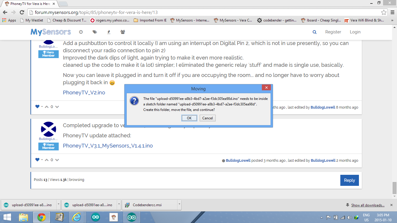
-
@BulldogLowell In the final stage of boxing this unit I like it and sure will use it in the coming months.
Question is when it was included to vera she made the node and then created the light node for it complete with on and off buttons, are they supposed to work or ignore these and use the local interrupt on d2 but would be cool to control this remotely with vera or in a scene.Great project!
@5546dug said:
are they supposed to work or ignore these and use the local interrupt on d2
you will be able to turn on/off at the controller and with the (quite optional) attached button!
do you need it to work just by the button, and no controller? that is an easy mod if that is your use case.
-
@BulldogLowell , In a perfect world I would like to control Phoney TV over vera/my sensors.
right now I can use RST to drop the lights for a few secs only, but that is a physical action .I did look at phoney tv 2.0 and see the pin was changed to pinbutton and declared as an output?
There was a relay in this sketch, or is the vera switch node to be therelay ? I see when you push button it changes the state of the lights but I think not the power to the nano.I guessing my guesses are wrong.
Enough guessing from an old guy!
Hello! It looks like you're interested in this conversation, but you don't have an account yet.
Getting fed up of having to scroll through the same posts each visit? When you register for an account, you'll always come back to exactly where you were before, and choose to be notified of new replies (either via email, or push notification). You'll also be able to save bookmarks and upvote posts to show your appreciation to other community members.
With your input, this post could be even better 💗
Register Login