Problem getting the code to run with MySensors library 2.0
-
Okay....so you are really having a strange problem here.
Am using the Arduino version 1.6.8,
Can you consider upgrading your arduino version maybe that could fix the CRC thing...1.6.8 is the older version. 1.6.12 is the latest version.
And the CRC error is the known bug. So, if your IDE and MySensors work then don't change anything.
-
Okay....so you are really having a strange problem here.
Am using the Arduino version 1.6.8,
Can you consider upgrading your arduino version maybe that could fix the CRC thing... -
@palande.vaibhav said:
Cause I can't use MY_GATEWAY_SERIAL for a node. Right?
Yes you can. But I read that there is a bug in MySensors 2.0 that causes the presentation function to not run, so you'll need the latest code from the MySensors development branch on Github.
@mfalkvidd said:
@palande.vaibhav said:
Cause I can't use MY_GATEWAY_SERIAL for a node. Right?
Yes you can. But I read that there is a bug in MySensors 2.0 that causes the presentation function to not run, so you'll need the latest code from the MySensors development branch on Github.
But am I right that for MySensors version 2.0, we must have #define MY_GATEWAY_SERIAL line in order for the code to work? OR is it just me?
And I don't even have anything in the presentation function. I think my problem is loop function not working if I don;t have #define MY_GATEWAY_SERIAL line in the code.
-
@palande.vaibhav said:
Cause I can't use MY_GATEWAY_SERIAL for a node. Right?
Yes you can. But I read that there is a bug in MySensors 2.0 that causes the presentation function to not run, so you'll need the latest code from the MySensors development branch on Github.
@mfalkvidd said:
@palande.vaibhav said:
Cause I can't use MY_GATEWAY_SERIAL for a node. Right?
Yes you can. But I read that there is a bug in MySensors 2.0 that causes the presentation function to not run, so you'll need the latest code from the MySensors development branch on Github.
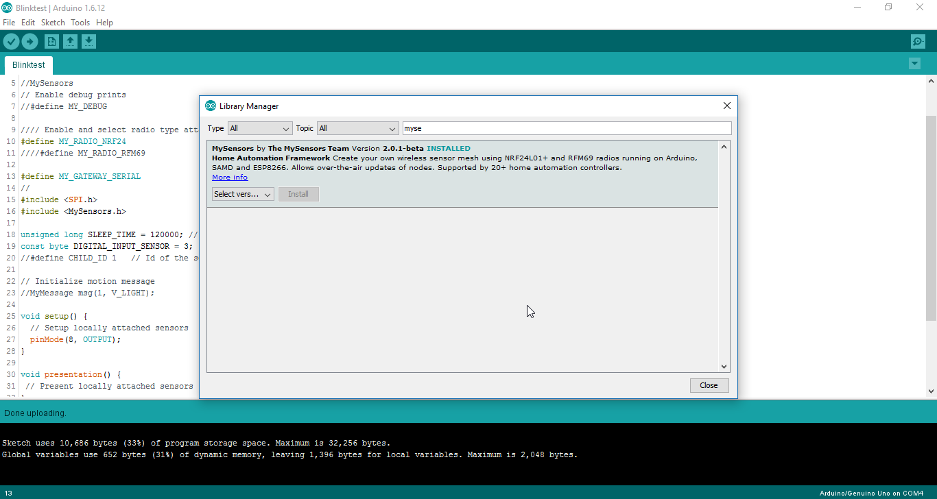
I tried with the library from Development branch on GitHub. It still doesn't work.
I must have #define MY_GATEWAY_SERIAL line in the code for the code to work with MySensors.h.Library version:
Code below doesn't work cause I have commented #define MY_GATEWAY_SERIAL: Just uncomment it and the same code works
//MySensors // Enable debug prints //#define MY_DEBUG //// Enable and select radio type attached #define MY_RADIO_NRF24 ////#define MY_RADIO_RFM69 //#define MY_GATEWAY_SERIAL #include <SPI.h> #include <MySensors.h> unsigned long SLEEP_TIME = 120000; // Sleep time between reports (in milliseconds) const byte DIGITAL_INPUT_SENSOR = 3; // The digital input you attached your motion sensor. (Only 2 and 3 generates interrupt!) //#define CHILD_ID 1 // Id of the sensor child // Initialize motion message //MyMessage msg(1, V_LIGHT); void setup() { // Setup locally attached sensors pinMode(8, OUTPUT); } void presentation() { // Present locally attached sensors } void loop() { // Send locally attached sensor data here digitalWrite(8, HIGH); // turn the LED on (HIGH is the voltage level) delay(1000); // wait for a second digitalWrite(8, LOW); // turn the LED off by making the voltage LOW delay(1000); // wait for a second } -
@palande.vaibhav said:
Cause I can't use MY_GATEWAY_SERIAL for a node. Right?
Yes you can. But I read that there is a bug in MySensors 2.0 that causes the presentation function to not run, so you'll need the latest code from the MySensors development branch on Github.
I saw the post about the presentation function not working in 2.0. But that has been fixed in development version.
My problem is still there that code doesn't work at all. To which I think my loop function stops working if I don't have #define MY_GATEWAY_SERIAL line in the code.
-
I saw the post about the presentation function not working in 2.0. But that has been fixed in development version.
My problem is still there that code doesn't work at all. To which I think my loop function stops working if I don't have #define MY_GATEWAY_SERIAL line in the code.
-
@palande.vaibhav what does the debug output say?
You can also add a few Serial.println in the code to see where the execution stops.@mfalkvidd
Thanx for the suggestion. It's worse than I thought.Here is the code:
//MySensors
// Enable debug prints
//#define MY_DEBUG

//// Enable and select radio type attached
#define MY_RADIO_NRF24
////#define MY_RADIO_RFM69

#define MY_GATEWAY_SERIAL

#include <SPI.h>
#include <MySensors.h>

// Initialize motion message
//MyMessage msg(1, V_LIGHT);

void setup() {
  // Setup locally attached sensors
  pinMode(8, OUTPUT);
  Serial.println("Setup runs");
}

void presentation() {
 // Present locally attached sensors
 Serial.println("presentation runs");
}

void loop() {
  // Send locally attached sensor data here
  Serial.println("loop runs");
   digitalWrite(8, HIGH);   // turn the LED on (HIGH is the voltage level)
  delay(1000);              // wait for a second
  digitalWrite(8, LOW);    // turn the LED off by making the voltage LOW
  delay(1000);              // wait for a second
}
This is the output with #define MY_GATEWAY_SERIAL line.
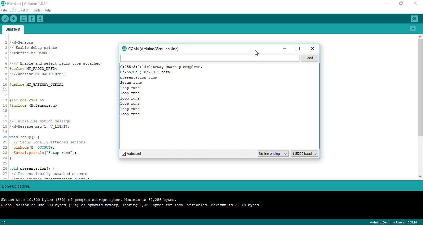
Without #define MY_GATEWAY_SERIAL, it doesn't show anything on the serial monitor.
-
@ayo
did you try commenting #define MY_GATEWAY_SERIAL and running your Blink code?
Can you please try that? -
@mfalkvidd
Thanx for the suggestion. It's worse than I thought.Here is the code:
//MySensors
// Enable debug prints
//#define MY_DEBUG

//// Enable and select radio type attached
#define MY_RADIO_NRF24
////#define MY_RADIO_RFM69

#define MY_GATEWAY_SERIAL

#include <SPI.h>
#include <MySensors.h>

// Initialize motion message
//MyMessage msg(1, V_LIGHT);

void setup() {
  // Setup locally attached sensors
  pinMode(8, OUTPUT);
  Serial.println("Setup runs");
}

void presentation() {
 // Present locally attached sensors
 Serial.println("presentation runs");
}

void loop() {
  // Send locally attached sensor data here
  Serial.println("loop runs");
   digitalWrite(8, HIGH);   // turn the LED on (HIGH is the voltage level)
  delay(1000);              // wait for a second
  digitalWrite(8, LOW);    // turn the LED off by making the voltage LOW
  delay(1000);              // wait for a second
}
This is the output with #define MY_GATEWAY_SERIAL line.
Without #define MY_GATEWAY_SERIAL, it doesn't show anything on the serial monitor.
@palande.vaibhav said:
@mfalkvidd
Thanx for the suggestion. It's worse than I thought.Here is the code:
//MySensors
// Enable debug prints
//#define MY_DEBUG

//// Enable and select radio type attached
#define MY_RADIO_NRF24
////#define MY_RADIO_RFM69

#define MY_GATEWAY_SERIAL

#include <SPI.h>
#include <MySensors.h>

// Initialize motion message
//MyMessage msg(1, V_LIGHT);

void setup() {
  // Setup locally attached sensors
  pinMode(8, OUTPUT);
  Serial.println("Setup runs");
}

void presentation() {
 // Present locally attached sensors
 Serial.println("presentation runs");
}

void loop() {
  // Send locally attached sensor data here
  Serial.println("loop runs");
   digitalWrite(8, HIGH);   // turn the LED on (HIGH is the voltage level)
  delay(1000);              // wait for a second
  digitalWrite(8, LOW);    // turn the LED off by making the voltage LOW
  delay(1000);              // wait for a second
}
This is the output with #define MY_GATEWAY_SERIAL line.
Without #define MY_GATEWAY_SERIAL, it doesn't show anything on the serial monitor.
@mfalkvidd Any update on this?
-
I don't have access to my computer now I will try it when I have it.
@palande.vaibhav said:
@ayo
did you try commenting #define MY_GATEWAY_SERIAL and running your Blink code?
Can you please try that? -
@palande.vaibhav no, I haven't got any ideas on what could be wrong. Sorry.
@mfalkvidd
Is it only me?
Can you please try this on your setup as time permits?
I have a manual install of the library 2.0
I want to use this for one of my projects and I am dead stuck. -
@palande.vaibhav said:
Cause I can't use MY_GATEWAY_SERIAL for a node. Right?
Yes you can. But I read that there is a bug in MySensors 2.0 that causes the presentation function to not run, so you'll need the latest code from the MySensors development branch on Github.
@mfalkvidd
I have to keep #define MY_GATEWAY_SERIAL line in the code for both gateway and sensor nodes.
Now since I have #define MY_GATEWAY_SERIAL line in the code for both gateway and sensor node, both of them are initializing as gateways.
And this causes them not to be able to communicate with each other.
Please help
-
@ayo Did you try running the code?
So I tried the whole code thing again as you have requested and I notice something weird happening to the device.
This is the code below//// Enable debug prints to serial monitor //#define MY_DEBUG // // //// Enable and select radio type attached #define MY_RADIO_NRF24 ////#define MY_RADIO_RFM69 // //// Set LOW transmit power level as default, if you have an amplified NRF-module and //// power your radio separately with a good regulator you can turn up PA level. //#define MY_RF24_PA_LEVEL RF24_PA_LOW // //// Enable serial gateway //#define MY_GATEWAY_SERIAL #include <SPI.h> #include <MySensors.h> void setup() { // Setup locally attached sensors pinMode(8, OUTPUT); } void presentation() { // Present locally attached sensors Serial.println("Presentation Runs"); } void loop() { // Send locally attached sensor data here digitalWrite(8, HIGH); // turn the LED on (HIGH is the voltage level) delay(1000); // wait for a second digitalWrite(8, LOW); // turn the LED off by making the voltage LOW delay(1000); // wait for a second Serial.println("Loop is running");}
After I commented out #define MY_GATEWAY_SERIAL nothing really happens on the serial monitor as you have said.
No blinking nor display on the monitor.So I went back to the code and enable #define MY_DEBUG to see what was actually happening....
THEN..I figured out what was happening
I uploaded the new code with #define MY_Debug uncomment and #define MY_Gateway_Serial still commented out I got this one the serial monitorStarting sensor (RNNNA-, 2.0.0) TSM:INIT TSM:RADIO:OK TSM:FPAR TSP:MSG:SEND 255-255-255-255 s=255,c=3,t=7,pt=0,l=0,sg=0,ft=0,st=bc: TSM:FPAR TSP:MSG:SEND 255-255-255-255 s=255,c=3,t=7,pt=0,l=0,sg=0,ft=0,st=bc: TSM:FPAR TSP:MSG:SEND 255-255-255-255 s=255,c=3,t=7,pt=0,l=0,sg=0,ft=0,st=bc: TSM:FPAR TSP:MSG:SEND 255-255-255-255 s=255,c=3,t=7,pt=0,l=0,sg=0,ft=0,st=bc: !TSM:FPAR:FAIL !TSM:FAILURE TSM:PDT TSM:INIT TSM:RADIO:OK TSM:FPAR TSP:MSG:SEND 255-255-255-255 s=255,c=3,t=7,pt=0,l=0,sg=0,ft=0,st=bc: TSM:FPAR TSP:MSG:SEND 255-255-255-255 s=255,c=3,t=7,pt=0,l=0,sg=0,ft=0,st=bc: TSM:FPAR TSP:MSG:SEND 255-255-255-255 s=255,c=3,t=7,pt=0,l=0,sg=0,ft=0,st=bc:From the result, the device is working as a node and trying to communicate with the parent/gateway and it enters an endless retry loop that keeps trying to communicate with the gateway. This is the reason i suppose nothing seems to be working because it is stuck trying to connect to the parent.
The Addition of #define MY_GATEWAY_SERIAL makes it already a gateway/parent device and avoids that endless loop thing.@palande.vaibhav said:
@ayo Did you try running the code?
-
I think one way to go about making it work is to edit that element of the mysensor main code that makes it enter an infinite retry loop is to is to make it retry for about maybe 3 times if no connection still it should raise a flag and leaves the loop and continue into the main code.
-
So I tried the whole code thing again as you have requested and I notice something weird happening to the device.
This is the code below//// Enable debug prints to serial monitor //#define MY_DEBUG // // //// Enable and select radio type attached #define MY_RADIO_NRF24 ////#define MY_RADIO_RFM69 // //// Set LOW transmit power level as default, if you have an amplified NRF-module and //// power your radio separately with a good regulator you can turn up PA level. //#define MY_RF24_PA_LEVEL RF24_PA_LOW // //// Enable serial gateway //#define MY_GATEWAY_SERIAL #include <SPI.h> #include <MySensors.h> void setup() { // Setup locally attached sensors pinMode(8, OUTPUT); } void presentation() { // Present locally attached sensors Serial.println("Presentation Runs"); } void loop() { // Send locally attached sensor data here digitalWrite(8, HIGH); // turn the LED on (HIGH is the voltage level) delay(1000); // wait for a second digitalWrite(8, LOW); // turn the LED off by making the voltage LOW delay(1000); // wait for a second Serial.println("Loop is running");}
After I commented out #define MY_GATEWAY_SERIAL nothing really happens on the serial monitor as you have said.
No blinking nor display on the monitor.So I went back to the code and enable #define MY_DEBUG to see what was actually happening....
THEN..I figured out what was happening
I uploaded the new code with #define MY_Debug uncomment and #define MY_Gateway_Serial still commented out I got this one the serial monitorStarting sensor (RNNNA-, 2.0.0) TSM:INIT TSM:RADIO:OK TSM:FPAR TSP:MSG:SEND 255-255-255-255 s=255,c=3,t=7,pt=0,l=0,sg=0,ft=0,st=bc: TSM:FPAR TSP:MSG:SEND 255-255-255-255 s=255,c=3,t=7,pt=0,l=0,sg=0,ft=0,st=bc: TSM:FPAR TSP:MSG:SEND 255-255-255-255 s=255,c=3,t=7,pt=0,l=0,sg=0,ft=0,st=bc: TSM:FPAR TSP:MSG:SEND 255-255-255-255 s=255,c=3,t=7,pt=0,l=0,sg=0,ft=0,st=bc: !TSM:FPAR:FAIL !TSM:FAILURE TSM:PDT TSM:INIT TSM:RADIO:OK TSM:FPAR TSP:MSG:SEND 255-255-255-255 s=255,c=3,t=7,pt=0,l=0,sg=0,ft=0,st=bc: TSM:FPAR TSP:MSG:SEND 255-255-255-255 s=255,c=3,t=7,pt=0,l=0,sg=0,ft=0,st=bc: TSM:FPAR TSP:MSG:SEND 255-255-255-255 s=255,c=3,t=7,pt=0,l=0,sg=0,ft=0,st=bc:From the result, the device is working as a node and trying to communicate with the parent/gateway and it enters an endless retry loop that keeps trying to communicate with the gateway. This is the reason i suppose nothing seems to be working because it is stuck trying to connect to the parent.
The Addition of #define MY_GATEWAY_SERIAL makes it already a gateway/parent device and avoids that endless loop thing.@palande.vaibhav said:
@ayo Did you try running the code?
@ayo
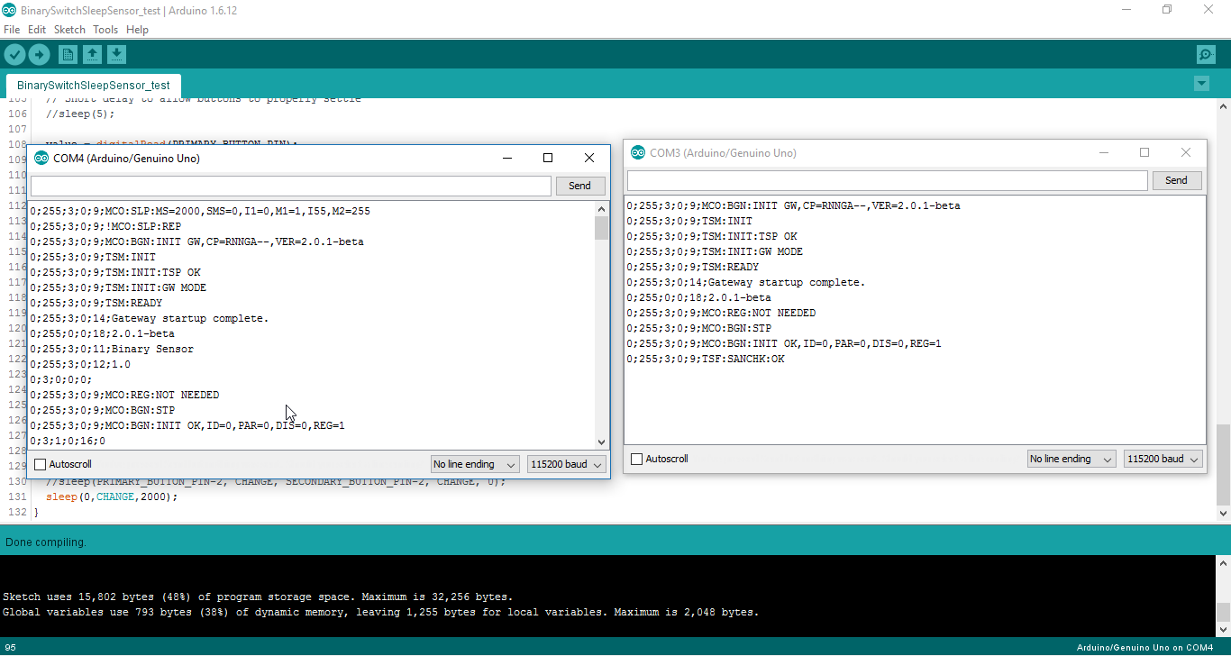
But adding #define MY_GATEWAY_SERIAL to the code for the sensor node will make it a gateway. Right? Please check my last post where I posted the screenshots of this making both of them initialize as the gateway.And if both are gateways they won't communicate
-
@ayo
But adding #define MY_GATEWAY_SERIAL to the code for the sensor node will make it a gateway. Right? Please check my last post where I posted the screenshots of this making both of them initialize as the gateway.And if both are gateways they won't communicate
Yes they won't communicate
@palande.vaibhav said:
@ayo
But adding #define MY_GATEWAY_SERIAL to the code for the sensor node will make it a gateway. Right? Please check my last post where I posted the screenshots of this making both of them initialize as the gateway.And if both are gateways they won't communicate
-
@ayo
Then this makes library 2.0 completely useless cause we always have to use MY_GATEWAY_SERIAL and so can't create sensor nodes.If you also confirm this then I am gonna report this as a bug.
No it is not like that.
You can create sensor nodes without the MY_Gateway_Serial thing, you just have to make sure that you have one device acting as a gateway device and the rest as a sensor node and everything will work very fine.
The reason you are having problem is because you are only building with one device and the library requires at-least 2 devices to work.
@palande.vaibhav said:
@ayo
Then this makes library 2.0 completely useless cause we always have to use MY_GATEWAY_SERIAL and so can't create sensor nodes.If you also confirm this then I am gonna report this as a bug.
-
No it is not like that.
You can create sensor nodes without the MY_Gateway_Serial thing, you just have to make sure that you have one device acting as a gateway device and the rest as a sensor node and everything will work very fine.
The reason you are having problem is because you are only building with one device and the library requires at-least 2 devices to work.
@palande.vaibhav said:
@ayo
Then this makes library 2.0 completely useless cause we always have to use MY_GATEWAY_SERIAL and so can't create sensor nodes.If you also confirm this then I am gonna report this as a bug.
@ayo
How can I make sensor nodes with the MY_GATEWAY_SERIAL line in the code. This just makes the device a gateway. How do I make it a sensor node with that line included?Just having two different devices in the same code will work??
Like in this code:
/**
 * The MySensors Arduino library handles the wireless radio link and protocol
 * between your home built sensors/actuators and HA controller of choice.
 * The sensors forms a self healing radio network with optional repeaters. Each
 * repeater and gateway builds a routing tables in EEPROM which keeps track of the
 * network topology allowing messages to be routed to nodes.
 *
 * Created by Henrik Ekblad <henrik.ekblad@mysensors.org>
 * Copyright (C) 2013-2015 Sensnology AB
 * Full contributor list: https://github.com/mysensors/Arduino/graphs/contributors
 *
 * Documentation: http://www.mysensors.org
 * Support Forum: http://forum.mysensors.org
 *
 * This program is free software; you can redistribute it and/or
 * modify it under the terms of the GNU General Public License
 * version 2 as published by the Free Software Foundation.
 *
 *******************************
 *
 * DESCRIPTION
 *
 * Interrupt driven binary switch example with dual interrupts
 * Author: Patrick 'Anticimex' Fallberg
 * Connect one button or door/window reed switch between
 * digitial I/O pin 3 (BUTTON_PIN below) and GND and the other
 * one in similar fashion on digital I/O pin 2.
 * This example is designed to fit Arduino Nano/Pro Mini
 *
 */


// Enable debug prints to serial monitor
#define MY_DEBUG

// Enable and select radio type attached
#define MY_RADIO_NRF24
//#define MY_RADIO_RFM69

//#define MY_GATEWAY_SERIAL

#define MY_NODE_ID 1

#include <SPI.h>
#include <MySensors.h>

#define SKETCH_NAME "Binary Sensor"
#define SKETCH_MAJOR_VER "1"
#define SKETCH_MINOR_VER "0"

#define PRIMARY_CHILD_ID 3
#define SECONDARY_CHILD_ID 4

#define PRIMARY_BUTTON_PIN 2   // Arduino Digital I/O pin for button/reed switch
#define SECONDARY_BUTTON_PIN 3 // Arduino Digital I/O pin for button/reed switch

#if (PRIMARY_BUTTON_PIN < 2 || PRIMARY_BUTTON_PIN > 3)
#error PRIMARY_BUTTON_PIN must be either 2 or 3 for interrupts to work
#endif
#if (SECONDARY_BUTTON_PIN < 2 || SECONDARY_BUTTON_PIN > 3)
#error SECONDARY_BUTTON_PIN must be either 2 or 3 for interrupts to work
#endif
#if (PRIMARY_BUTTON_PIN == SECONDARY_BUTTON_PIN)
#error PRIMARY_BUTTON_PIN and BUTTON_PIN2 cannot be the same
#endif
#if (PRIMARY_CHILD_ID == SECONDARY_CHILD_ID)
#error PRIMARY_CHILD_ID and SECONDARY_CHILD_ID cannot be the same
#endif


// Change to V_LIGHT if you use S_LIGHT in presentation below
MyMessage msg(PRIMARY_CHILD_ID, V_TRIPPED);
MyMessage msg2(SECONDARY_CHILD_ID, V_TRIPPED);

void setup()
{
  // Setup the buttons
  pinMode(PRIMARY_BUTTON_PIN, INPUT);
  pinMode(SECONDARY_BUTTON_PIN, INPUT);
  pinMode(8,OUTPUT);

  // Activate internal pull-ups
  digitalWrite(PRIMARY_BUTTON_PIN, HIGH);
  digitalWrite(SECONDARY_BUTTON_PIN, HIGH);

  Serial.begin(115200);
}

void presentation() {
  // Send the sketch version information to the gateway and Controller
  sendSketchInfo(SKETCH_NAME, SKETCH_MAJOR_VER "." SKETCH_MINOR_VER);

   Register binary input sensor to sensor_node (they will be created as child devices)
   You can use S_DOOR, S_MOTION or S_LIGHT here depending on your usage.
   If S_LIGHT is used, remember to update variable type you send in. See "msg" above.
  present(PRIMARY_CHILD_ID, S_DOOR);
  present(SECONDARY_CHILD_ID, S_DOOR);
}

// Loop will iterate on changes on the BUTTON_PINs
void loop()
{
  uint8_t value;
  static uint8_t sentValue=2;
  static uint8_t sentValue2=2;

  // Short delay to allow buttons to properly settle
  //sleep(5);

  value = digitalRead(PRIMARY_BUTTON_PIN);

  if (value != sentValue) {
     // Value has changed from last transmission, send the updated value
     send(msg.set(value==HIGH ? 1 : 0));
     digitalWrite(8,!(digitalRead(8)));

     String string = "Value changed to: ";

     Serial.println(string += value);
     sentValue = value;
  }

  value = digitalRead(SECONDARY_BUTTON_PIN);

  if (value != sentValue2) {
     // Value has changed from last transmission, send the updated value
     send(msg2.set(value==HIGH ? 1 : 0));
     sentValue2 = value;
  }

  // Sleep until something happens with the sensor
  sleep(PRIMARY_BUTTON_PIN-2, CHANGE, SECONDARY_BUTTON_PIN-2, CHANGE, 0);
  //sleep(0,CHANGE,0);
}
Hello! It looks like you're interested in this conversation, but you don't have an account yet.
Getting fed up of having to scroll through the same posts each visit? When you register for an account, you'll always come back to exactly where you were before, and choose to be notified of new replies (either via email, or push notification). You'll also be able to save bookmarks and upvote posts to show your appreciation to other community members.
With your input, this post could be even better 💗
Register Login