Slim Node as a Mini 2AA Battery PIR Motion Sensor
-
Hello, when running the "Motion Detector sketch from the mysensors-examples" on these nodes with the 1Mhz bootloader with 2aa batteries some nodes freeze after appr. 24h .
Some continue working, i cant find the problem.
Does anybody have a idea what could cause those freezes ?
Thanks in advance -
@m26872 Thanks for your answer and thanks for this superb node :) :)
No, i didnt put the additional sleep in , where should I put this ? Im a little confused.../** * The MySensors Arduino library handles the wireless radio link and protocol * between your home built sensors/actuators and HA controller of choice. * The sensors forms a self healing radio network with optional repeaters. Each * repeater and gateway builds a routing tables in EEPROM which keeps track of the * network topology allowing messages to be routed to nodes. * * Created by Henrik Ekblad <henrik.ekblad@mysensors.org> * Copyright (C) 2013-2015 Sensnology AB * Full contributor list: https://github.com/mysensors/Arduino/graphs/contributors * * Documentation: http://www.mysensors.org * Support Forum: http://forum.mysensors.org * * This program is free software; you can redistribute it and/or * modify it under the terms of the GNU General Public License * version 2 as published by the Free Software Foundation. * ******************************* * * REVISION HISTORY * Version 1.0 - Henrik Ekblad * * DESCRIPTION * Motion Sensor example using HC-SR501 * http://www.mysensors.org/build/motion * */ // Enable debug prints // #define MY_DEBUG // Enable and select radio type attached #define MY_RADIO_NRF24 //#define MY_RADIO_RFM69 #include <MySensors.h> unsigned long SLEEP_TIME = 120000; // Sleep time between reports (in milliseconds) #define DIGITAL_INPUT_SENSOR 3 // The digital input you attached your motion sensor. (Only 2 and 3 generates interrupt!) #define CHILD_ID 1 // Id of the sensor child // Initialize motion message MyMessage msg(CHILD_ID, V_TRIPPED); void setup() { pinMode(DIGITAL_INPUT_SENSOR, INPUT); // sets the motion sensor digital pin as input } void presentation() { // Send the sketch version information to the gateway and Controller sendSketchInfo("Motion Sensor", "1.0"); // Register all sensors to gw (they will be created as child devices) present(CHILD_ID, S_MOTION); } void loop() { // Read digital motion value bool tripped = digitalRead(DIGITAL_INPUT_SENSOR) == HIGH; Serial.println(tripped); send(msg.set(tripped?"1":"0")); // Send tripped value to gw // Sleep until interrupt comes in on motion sensor. Send update every two minute. sleep(digitalPinToInterrupt(DIGITAL_INPUT_SENSOR), CHANGE, SLEEP_TIME); }``` -
@m26872 Thanks for your answer and thanks for this superb node :) :)
No, i didnt put the additional sleep in , where should I put this ? Im a little confused.../** * The MySensors Arduino library handles the wireless radio link and protocol * between your home built sensors/actuators and HA controller of choice. * The sensors forms a self healing radio network with optional repeaters. Each * repeater and gateway builds a routing tables in EEPROM which keeps track of the * network topology allowing messages to be routed to nodes. * * Created by Henrik Ekblad <henrik.ekblad@mysensors.org> * Copyright (C) 2013-2015 Sensnology AB * Full contributor list: https://github.com/mysensors/Arduino/graphs/contributors * * Documentation: http://www.mysensors.org * Support Forum: http://forum.mysensors.org * * This program is free software; you can redistribute it and/or * modify it under the terms of the GNU General Public License * version 2 as published by the Free Software Foundation. * ******************************* * * REVISION HISTORY * Version 1.0 - Henrik Ekblad * * DESCRIPTION * Motion Sensor example using HC-SR501 * http://www.mysensors.org/build/motion * */ // Enable debug prints // #define MY_DEBUG // Enable and select radio type attached #define MY_RADIO_NRF24 //#define MY_RADIO_RFM69 #include <MySensors.h> unsigned long SLEEP_TIME = 120000; // Sleep time between reports (in milliseconds) #define DIGITAL_INPUT_SENSOR 3 // The digital input you attached your motion sensor. (Only 2 and 3 generates interrupt!) #define CHILD_ID 1 // Id of the sensor child // Initialize motion message MyMessage msg(CHILD_ID, V_TRIPPED); void setup() { pinMode(DIGITAL_INPUT_SENSOR, INPUT); // sets the motion sensor digital pin as input } void presentation() { // Send the sketch version information to the gateway and Controller sendSketchInfo("Motion Sensor", "1.0"); // Register all sensors to gw (they will be created as child devices) present(CHILD_ID, S_MOTION); } void loop() { // Read digital motion value bool tripped = digitalRead(DIGITAL_INPUT_SENSOR) == HIGH; Serial.println(tripped); send(msg.set(tripped?"1":"0")); // Send tripped value to gw // Sleep until interrupt comes in on motion sensor. Send update every two minute. sleep(digitalPinToInterrupt(DIGITAL_INPUT_SENSOR), CHANGE, SLEEP_TIME); }```@Komaandy said in Slim Node as a Mini 2AA Battery PIR Motion Sensor:
I meant like this (look in code below), but it's just a wild guess.
/** * The MySensors Arduino library handles the wireless radio link and protocol * between your home built sensors/actuators and HA controller of choice. * The sensors forms a self healing radio network with optional repeaters. Each * repeater and gateway builds a routing tables in EEPROM which keeps track of the * network topology allowing messages to be routed to nodes. * * Created by Henrik Ekblad <henrik.ekblad@mysensors.org> * Copyright (C) 2013-2015 Sensnology AB * Full contributor list: https://github.com/mysensors/Arduino/graphs/contributors * * Documentation: http://www.mysensors.org * Support Forum: http://forum.mysensors.org * * This program is free software; you can redistribute it and/or * modify it under the terms of the GNU General Public License * version 2 as published by the Free Software Foundation. * ******************************* * * REVISION HISTORY * Version 1.0 - Henrik Ekblad * * DESCRIPTION * Motion Sensor example using HC-SR501 * http://www.mysensors.org/build/motion * */ // Enable debug prints // #define MY_DEBUG // Enable and select radio type attached #define MY_RADIO_NRF24 //#define MY_RADIO_RFM69 #include <MySensors.h> unsigned long SLEEP_TIME = 120000; // Sleep time between reports (in milliseconds) #define DIGITAL_INPUT_SENSOR 3 // The digital input you attached your motion sensor. (Only 2 and 3 generates interrupt!) #define CHILD_ID 1 // Id of the sensor child // Initialize motion message MyMessage msg(CHILD_ID, V_TRIPPED); void setup() { pinMode(DIGITAL_INPUT_SENSOR, INPUT); // sets the motion sensor digital pin as input } void presentation() { // Send the sketch version information to the gateway and Controller sendSketchInfo("Motion Sensor", "1.0"); // Register all sensors to gw (they will be created as child devices) present(CHILD_ID, S_MOTION); } void loop() { // Read digital motion value bool tripped = digitalRead(DIGITAL_INPUT_SENSOR) == HIGH; Serial.println(tripped); send(msg.set(tripped?"1":"0")); // Send tripped value to gw sleep(3000); // Sleep 3s to make sure everything is stable before we start to sleep with interrupts. // Sleep until interrupt comes in on motion sensor. Send update every two minute. sleep(digitalPinToInterrupt(DIGITAL_INPUT_SENSOR), CHANGE, SLEEP_TIME); }``` -
@m26872 said in Slim Node as a Mini 2AA Battery PIR Motion Sensor:
Removing the 7133-regulator did not affect anything significantly due to its very low quiescent current (see datasheet, perhaps useful in some other project?)
ok, does that mean one does not have to remove the voltage regulator and the diode? @AWI is saying one must modify the PIR and now I am irritated...
-
@siod
I removed both to make the smaller ( HC-SR505 ) work with ~3Volt and bridged these contacts as shown in the picture
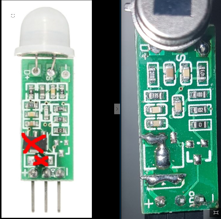
They work perfectly fine for me and are not too sensitive.
Actually they dont even react on my cats, which is nice, because the "bigger" HC-SR501 always did... :) -
And with the "bigger" HC-SR501 all one need to do is obviously to connect the VCC to the pad or pin.
For me at least it is working pretty fine as well. No false positives or anything else negative.
Of course you have to remove the jumper first.
-
@m26872 said in Slim Node as a Mini 2AA Battery PIR Motion Sensor:
Removing the 7133-regulator did not affect anything significantly due to its very low quiescent current (see datasheet, perhaps useful in some other project?)
ok, does that mean one does not have to remove the voltage regulator and the diode? @AWI is saying one must modify the PIR and now I am irritated...
@siod said in Slim Node as a Mini 2AA Battery PIR Motion Sensor:
@m26872 said in Slim Node as a Mini 2AA Battery PIR Motion Sensor:
Removing the 7133-regulator did not affect anything significantly due to its very low quiescent current (see datasheet, perhaps useful in some other project?)
ok, does that mean one does not have to remove the voltage regulator and the diode? @AWI is saying one must modify the PIR and now I am irritated...
That was only regarding the power consumption. I don't remember the voltage drops but I guess you'll get to it work with 2AA but for a shorter time. Why wont you remove them?
-
ok guys, I tried the mini PIR and the big one, on the mini PIR I removed the regulator and diode just as explained and I uploaded this sketch
/**
 * EgSlimReed2
 * Sketch for Slim Node and HC-SR505 based motion sensor.
 * Inspired by:
 * - MySensors motion sensor example: http://www.mysensors.org/build/motion
 * - AWI's CR123A based Slim Node motion sensor: http://forum.mysensors.org/topic/2478/slim-cr123a-2aa-battery-node
 *
 * Created by m26872
 * Documentation: http://forum.mysensors.org...
 *
 * This program is free software; you can redistribute it and/or
 * modify it under the terms of the GNU General Public License
 * version 2 as published by the Free Software Foundation.
 *
 *******************************
 *
 * REVISION HISTORY
 * Version 1.0 - Test to if node can operate in some way dealing with the Pir extreme sensitivity to noise on Vcc.
 * Version 2.0 - First "production node". "Inactivity day counter" introduced.
 *
 * DESCRIPTION
 * This sketch will only send trips as "1" to the controller. It's up to the controller to deal with the info.
 * The motion node will not notify controller when resets back to low state and is ready for a new trip. In reality
 * this is ~10s. And EVEN IF motion is detected continuously, there will be no new trip until motion has stopped for ~10s.
 * The HC-SR505 is very noise sensitive and will trigger spuriously for almost any activity
 * on Vcc (test thoroughly). To run the HC-505 at low voltages (tested flawlessly down to 1.6V),
 * the 7133-reg and diode are removed (and possibly increase the sensitivity even further).
 * Solution is to deal with it by interrupt type, check which source, block by sleep time etc.
 *
 * HC-505 output connects to MOTION_INPUT_PIN (here D3) without any supporting component. Input pull-up disabled.
 * Every 24 hrs without trip, increments a counter and after "BATTERY_REPORT_DAY" counts a battery report will be sent as a heartbeat signal.
 * Else a battery report will be sent after every "BATTERY_REPORT_BY_IRT_CYCLE" motion trips.
 *
 */

 //Sensor 21, erster PIR Sensor

#define MY_RADIO_NRF24 //MySensor Library auf NRF24 Funkmodul einstellen, muss vor MySensor.h Initialisierung geschehen
// Define Node ID
#define MY_NODE_ID 21
#define MY_PARENT_NODE_ID 0 //Repeater Node 1!
#define MY_PARENT_NODE_IS_STATIC

//Batterysensor
int BATTERY_SENSE_PIN = A0;  // select the input pin for the battery sense point
int oldBatteryPcnt = 0;
#define CHILD_ID_BATT 7

#include <MySensors.h>
#include <SPI.h>
#include <Vcc.h>


unsigned long SLEEP_TIME = 86400000; // Sleep time between reports (in milliseconds)
#define DIGITAL_INPUT_SENSOR 3   // The digital input you attached your motion sensor.  (Only 2 and 3 generates interrupt!)
#define CHILD_ID 1   // Id of the sensor child

//Battery
MyMessage msgbatt(CHILD_ID_BATT,V_VOLTAGE);
// Initialize motion message
MyMessage msg(CHILD_ID, V_TRIPPED);

void setup()
{
    pinMode(DIGITAL_INPUT_SENSOR, INPUT);      // sets the motion sensor digital pin as input

    //Batterysensor
     // use the 1.1 V internal reference
#if defined(__AVR_ATmega2560__)
   analogReference(INTERNAL1V1);
#else
   analogReference(INTERNAL);
#endif
}

void presentation()
{
    // Send the sketch version information to the gateway and Controller
    sendSketchInfo("Motion Sensor Keller_1", "1.0");

    // Register all sensors to gw (they will be created as child devices)
    present(CHILD_ID, S_MOTION);

    //Battery
    present(CHILD_ID_BATT,V_VOLTAGE);
}

void loop()
{
    //Batterysensor
  // get the battery Voltage
   int sensorValue = analogRead(BATTERY_SENSE_PIN);
   #ifdef DEBUG
   #endif

   // 1M, 470K divider across battery and using internal ADC ref of 1.1V
   // Sense point is bypassed with 0.1 uF cap to reduce noise at that point
   // ((1e6+470e3)/470e3)*1.1 = Vmax = 3.44 Volts
   // 3.44/1023 = Volts per bit = 0.003363075
   //float batteryV  = sensorValue * 0.003363075;
   int batteryPcnt = sensorValue / 10;

     sendBatteryLevel(batteryPcnt);
     wait(500);
     send(msgbatt.set(batteryPcnt));
     wait(500);
    // Read digital motion value
    bool tripped = digitalRead(DIGITAL_INPUT_SENSOR) == HIGH;

    Serial.println(tripped);
    send(msg.set(tripped?"1":"0"));  // Send tripped value to gw

    sleep(3000);  // Sleep 3s to make sure everything is stable before we start to sleep with interrupts.

    // Sleep until interrupt comes in on motion sensor. Send update every 24 hours.
    sleep(digitalPinToInterrupt(DIGITAL_INPUT_SENSOR), CHANGE, SLEEP_TIME);
}
But with any PIR I get continuos trip messages every 3 seconds. Any idea?
-
I am having the exact same issues with the Mysensor2.0 version ... (!)
When using Arduino IDE 1.65 and Mysensor 1.54 librarys and the sketch that is pinned in the header it works .
@Komaandy @siod
Did you try version 2.2 as in https://forum.mysensors.org/topic/6511/hc-sr501-3-3v-randomly-sends-tripped-when-radio-is-on/36 ? -
Nope, 2.2 is giving me the same fail trip messages.
When using IDE 1.6.5 with 1.5.4 I don´t even get it compiled, Arduino is automatically using 2.2.0 library from 1.8.2 version which is, of course, still installed on my system and I don´t want to uninstall it...edit: Ok, the way @komaandy proposed is working, though I like the other sketch more...
edit2: Well, seems like it has sth. to do with the battery sensing: when removing this part from void loop() it works as it is supposed to (see what I commented out between /* and */):
void loop()
{
    //Batterysensor
  // get the battery Voltage
   /*int sensorValue = analogRead(BATTERY_SENSE_PIN);
   #ifdef DEBUG
   #endif

   int batteryPcnt = sensorValue / 10;

     gw.sendBatteryLevel(batteryPcnt);
     gw.wait(500);
     gw.send(msgbatt.set(batteryPcnt));
     gw.wait(500);
  */
  if (interruptReturn) {  // Woke up by rising pin
  gw.send(msg.set("1"));  // Just send trip (set) commands to controller. (Let controller reset and decide what to do with it.)
  irtCounter++;

  }

  gw.sleep(3000);  // Make sure everything is stable before start to sleep with interrupts. (don't use "gw.wait()" here). Tests shows false trip ~2s after battery report otherwise.

  // Sleep until interrupt comes in on motion sensor or sleep time passed.
  interruptReturn = gw.sleep(MOTION_INPUT_PIN-2,CHANGE, ONE_DAY_SLEEP_TIME);
  // DEBUG_PRINT("interruptReturn: ");DEBUG_PRINTLN(interruptReturn);

}
edit3: I obviously mixed up things, now it seems like it´s working... I will report back after some time of testing, but this should be my working code:
/**
 * EgSlimReed2
 * Sketch for Slim Node and HC-SR505 based motion sensor.
 * Inspired by:
 * - MySensors motion sensor example: http://www.mysensors.org/build/motion
 * - AWI's CR123A based Slim Node motion sensor: http://forum.mysensors.org/topic/2478/slim-cr123a-2aa-battery-node
 *
 * Created by m26872
 * Documentation: http://forum.mysensors.org...
 *
 * This program is free software; you can redistribute it and/or
 * modify it under the terms of the GNU General Public License
 * version 2 as published by the Free Software Foundation.
 *
 *******************************
 *
 * REVISION HISTORY
 * Version 1.0 - Test to if node can operate in some way dealing with the Pir extreme sensitivity to noise on Vcc.
 * Version 2.0 - First "production node". "Inactivity day counter" introduced.
 *
 * DESCRIPTION
 * This sketch will only send trips as "1" to the controller. It's up to the controller to deal with the info.
 * The motion node will not notify controller when resets back to low state and is ready for a new trip. In reality
 * this is ~10s. And EVEN IF motion is detected continuously, there will be no new trip until motion has stopped for ~10s.
 * The HC-SR505 is very noise sensitive and will trigger spuriously for almost any activity
 * on Vcc (test thoroughly). To run the HC-505 at low voltages (tested flawlessly down to 1.6V),
 * the 7133-reg and diode are removed (and possibly increase the sensitivity even further).
 * Solution is to deal with it by interrupt type, check which source, block by sleep time etc.
 *
 * HC-505 output connects to MOTION_INPUT_PIN (here D3) without any supporting component. Input pull-up disabled.
 * Every 24 hrs without trip, increments a counter and after "BATTERY_REPORT_DAY" counts a battery report will be sent as a heartbeat signal.
 * Else a battery report will be sent after every "BATTERY_REPORT_BY_IRT_CYCLE" motion trips.
 *
 */

 #define MY_RADIO_NRF24 //MySensor Library auf NRF24 Funkmodul einstellen, muss vor MySensor.h Initialisierung geschehen
// Define Node ID
#define MY_NODE_ID 21
#define MY_PARENT_NODE_ID 0 //Repeater Node 1=50 / Gateway=0!
#define MY_PARENT_NODE_IS_STATIC

//Batterysensor
int BATTERY_SENSE_PIN = A0;  // select the input pin for the battery sense point
int oldBatteryPcnt = 0;
#define CHILD_ID_BATT 7

#include <MySensor.h>
#include <SPI.h>
#include <Vcc.h>

//#define DEBUG

#define SKETCH_NAME "Motion PIR Keller_1"
#define SKETCH_VERSION "2.0"
#define CHILD_ID 1
#define MOTION_INPUT_PIN 3
#define BATTERY_REPORT_DAY 2   // Desired heartbeat(battery report) interval when inactive.
#define BATTERY_REPORT_BY_IRT_CYCLE 10  // Make a battery report after this many trips. Maximum report interval will also be equal to this number of days.
#define ONE_DAY_SLEEP_TIME 86400000
#define VCC_MIN 1.9
#define VCC_MAX 3.3


#ifdef DEBUG
#define DEBUG_SERIAL(x) Serial.begin(x)
#define DEBUG_PRINT(x) Serial.print(x)
#define DEBUG_PRINTLN(x) Serial.println(x)
#else
#define DEBUG_SERIAL(x)
#define DEBUG_PRINT(x)
#define DEBUG_PRINTLN(x)
#endif

int dayCounter = BATTERY_REPORT_DAY;
int irtCounter = 0;


bool interruptReturn = false; // "false" will make the first loop disregard high output from HV-505 (from start-up) and make a battery report instead.

Vcc vcc;
MySensor gw;
MyMessage msg(CHILD_ID, V_TRIPPED);
//Battery
MyMessage msgbatt(CHILD_ID_BATT,V_VOLTAGE);

void setup()
{
      //Batterysensor
     // use the 1.1 V internal reference
#if defined(__AVR_ATmega2560__)
   analogReference(INTERNAL1V1);
#else
   analogReference(INTERNAL);
#endif

  DEBUG_SERIAL(9600);
  DEBUG_PRINTLN(("Serial started"));
  delay(100); // to settle power for radio
  gw.begin(NULL,MY_NODE_ID);
  pinMode(MOTION_INPUT_PIN, INPUT);
  digitalWrite(MOTION_INPUT_PIN, LOW);    // Disable internal pull-ups
  gw.sendSketchInfo(SKETCH_NAME, SKETCH_VERSION);
  gw.present(CHILD_ID, S_MOTION);
  DEBUG_PRINTLN("Warming and blocking PIR trip for 20s.");
  gw.sleep(20000); // Wait until HC-505 warmed-up and output returned low.
}
void presentation()
{
    // Send the sketch version information to the gateway and Controller
    gw.sendSketchInfo("Motion Sensor Keller_1", "1.0");

    // Register all sensors to gw (they will be created as child devices)
    gw.present(CHILD_ID, S_MOTION);

    //Battery
    gw.present(CHILD_ID_BATT,V_VOLTAGE);
}

void loop()
{
    //Batterysensor
  // get the battery Voltage
   /*int sensorValue = analogRead(BATTERY_SENSE_PIN);
   #ifdef DEBUG
   #endif

   int batteryPcnt = sensorValue / 10;

     gw.sendBatteryLevel(batteryPcnt);
     gw.wait(500);
     gw.send(msgbatt.set(batteryPcnt));
     gw.wait(500);
  */
  if (interruptReturn) {  // Woke up by rising pin
  gw.send(msg.set("1"));  // Just send trip (set) commands to controller. (Let controller reset and decide what to do with it.)
    irtCounter++;
  if (irtCounter>=BATTERY_REPORT_BY_IRT_CYCLE) {
    irtCounter=0;
    sendBatteryReport();
  }
  }
  else { // Woke up by timer  (or it's the first run)
  dayCounter++;
  if (dayCounter >= BATTERY_REPORT_DAY) {
      dayCounter = 0;
      sendBatteryReport();
  }
  }


  gw.sleep(3000);  // Make sure everything is stable before start to sleep with interrupts. (don't use "gw.wait()" here). Tests shows false trip ~2s after battery report otherwise.

  // Sleep until interrupt comes in on motion sensor or sleep time passed.
  interruptReturn = gw.sleep(MOTION_INPUT_PIN-2,CHANGE, ONE_DAY_SLEEP_TIME);
  // DEBUG_PRINT("interruptReturn: ");DEBUG_PRINTLN(interruptReturn);

}

void sendBatteryReport() {
      float p = vcc.Read_Perc(VCC_MIN, VCC_MAX, true);
      int batteryPcnt = static_cast<int>(p);
      gw.sendBatteryLevel(batteryPcnt);
}
edit4: ok, with my edited code this sketch is also working fine now with IDE 1.8.2 and lib 2.2.0 beta. So now everythings works fine!
/** * EgSlimReed2 * Sketch for Slim Node and HC-SR505 based motion sensor. * Inspired by: * - MySensors motion sensor example: http://www.mysensors.org/build/motion * - AWI's CR123A based Slim Node motion sensor: http://forum.mysensors.org/topic/2478/slim-cr123a-2aa-battery-node * * Created by m26872 * Documentation: http://forum.mysensors.org... * * This program is free software; you can redistribute it and/or * modify it under the terms of the GNU General Public License * version 2 as published by the Free Software Foundation. * ******************************* * * REVISION HISTORY * Version 1.0 - Test to if node can operate in some way dealing with the Pir extreme sensitivity to noise on Vcc. * Version 2.0 - First "production node". "Inactivity day counter" introduced. * * DESCRIPTION * This sketch will only send trips as "1" to the controller. It's up to the controller to deal with the info. * The motion node will not notify controller when resets back to low state and is ready for a new trip. In reality * this is ~10s. And EVEN IF motion is detected continuously, there will be no new trip until motion has stopped for ~10s. * The HC-SR505 is very noise sensitive and will trigger spuriously for almost any activity * on Vcc (test thoroughly). To run the HC-505 at low voltages (tested flawlessly down to 1.6V), * the 7133-reg and diode are removed (and possibly increase the sensitivity even further). * Solution is to deal with it by interrupt type, check which source, block by sleep time etc. * * HC-505 output connects to MOTION_INPUT_PIN (here D3) without any supporting component. Input pull-up disabled. * Every 24 hrs without trip, increments a counter and after "BATTERY_REPORT_DAY" counts a battery report will be sent as a heartbeat signal. * Else a battery report will be sent after every "BATTERY_REPORT_BY_IRT_CYCLE" motion trips. * */ //Sensor 21, erster PIR Sensor #define MY_RADIO_NRF24 //MySensor Library auf NRF24 Funkmodul einstellen, muss vor MySensor.h Initialisierung geschehen // Define Node ID #define MY_NODE_ID 21 #define MY_PARENT_NODE_ID 50 //Repeater Node 1! #define MY_PARENT_NODE_IS_STATIC //Batterysensor int BATTERY_SENSE_PIN = A0; // select the input pin for the battery sense point int oldBatteryPcnt = 0; #define CHILD_ID_BATT 7 #include <MySensors.h> #include <SPI.h> #include <Vcc.h> unsigned long SLEEP_TIME = 86400000; // Sleep time between reports (in milliseconds) #define DIGITAL_INPUT_SENSOR 3 // The digital input you attached your motion sensor. (Only 2 and 3 generates interrupt!) #define CHILD_ID 1 // Id of the sensor child #define BATTERY_REPORT_DAY 2 // Desired heartbeat(battery report) interval when inactive. #define BATTERY_REPORT_BY_IRT_CYCLE 10 // Make a battery report after this many trips. Maximum report interval will also be equal to this number of days. #define ONE_DAY_SLEEP_TIME 86400000 #define VCC_MIN 1.9 #define VCC_MAX 3.3 int dayCounter = BATTERY_REPORT_DAY; int irtCounter = 0; bool interruptReturn = false; // "false" will make the first loop disregard high output from HV-505 (from start-up) and make a battery report instead. Vcc vcc; //Battery MyMessage msgbatt(CHILD_ID_BATT,V_VOLTAGE); // Initialize motion message MyMessage msg(CHILD_ID, V_TRIPPED); void setup() { pinMode(DIGITAL_INPUT_SENSOR, INPUT); // sets the motion sensor digital pin as input //Batterysensor // use the 1.1 V internal reference #if defined(__AVR_ATmega2560__) analogReference(INTERNAL1V1); #else analogReference(INTERNAL); #endif } void presentation() { // Send the sketch version information to the gateway and Controller sendSketchInfo("Motion Sensor Keller_1", "1.0"); // Register all sensors to gw (they will be created as child devices) present(CHILD_ID, S_MOTION); //Battery present(CHILD_ID_BATT,V_VOLTAGE); } void loop() { //Batterysensor // get the battery Voltage /*int sensorValue = analogRead(BATTERY_SENSE_PIN); #ifdef DEBUG #endif // 1M, 470K divider across battery and using internal ADC ref of 1.1V // Sense point is bypassed with 0.1 uF cap to reduce noise at that point // ((1e6+470e3)/470e3)*1.1 = Vmax = 3.44 Volts // 3.44/1023 = Volts per bit = 0.003363075 //float batteryV = sensorValue * 0.003363075; int batteryPcnt = sensorValue / 10; sendBatteryLevel(batteryPcnt); wait(500); send(msgbatt.set(batteryPcnt)); wait(500); */ // Read digital motion value bool tripped = digitalRead(DIGITAL_INPUT_SENSOR) == HIGH; Serial.println(tripped); send(msg.set(tripped?"1":"0")); // Send tripped value to gw irtCounter++; if (irtCounter>=BATTERY_REPORT_BY_IRT_CYCLE) { irtCounter=0; sendBatteryReport(); } else { // Woke up by timer (or it's the first run) dayCounter++; if (dayCounter >= BATTERY_REPORT_DAY) { dayCounter = 0; sendBatteryReport(); } } sleep(3000); // Sleep 3s to make sure everything is stable before we start to sleep with interrupts. // Sleep until interrupt comes in on motion sensor. Send update every 24 hours. sleep(digitalPinToInterrupt(DIGITAL_INPUT_SENSOR), CHANGE, SLEEP_TIME); } void sendBatteryReport() { float p = vcc.Read_Perc(VCC_MIN, VCC_MAX, true); int batteryPcnt = static_cast<int>(p); sendBatteryLevel(batteryPcnt); } -
I know this is an old topic, but it seems tried and true, so.. How is everyone's experience with this design sofar? Has it been reliable? How far has the 24 month battery life claim held up?
I've been looking for a detection node that I could use for various tasks around the house (Motion detect, reed switch detect, even a simple door bell). But with a plain arduino pro mini I keep running into abysmal battery life. However this setup seems to handle a year on some AA batteries quite easily?
If I can get some confirmation on the reliability on these, I can pull the trigger on producing a handful of these slimnodes. ;)
-
I know this is an old topic, but it seems tried and true, so.. How is everyone's experience with this design sofar? Has it been reliable? How far has the 24 month battery life claim held up?
I've been looking for a detection node that I could use for various tasks around the house (Motion detect, reed switch detect, even a simple door bell). But with a plain arduino pro mini I keep running into abysmal battery life. However this setup seems to handle a year on some AA batteries quite easily?
If I can get some confirmation on the reliability on these, I can pull the trigger on producing a handful of these slimnodes. ;)
@Sven-0
Fun to see this old topic again. And also the coincidence, since my visits here have been rare for a long time. :disappointed:
Anyway, I'm running a few slimnodes since the beginning and have both good and bad experiences. In general, the battery lifetime is your least concern. Instead I have had issues with sensors, sensitivity, switch contact corrosion, mechanical robustness, wifi interference, repaeter, gateway, controller, waf, kids, animals, etc, etc.
Regarding this particular PIR slimnode it's very stable, but it is not universal for every situation due to the limited range and missing sinsitivity adjustment. E.g I can't use it too near my basement windows due to the moving cold air. And in my living room I have sun reflections to deal with.
I suggest you start by building a testnode to check if it works for your conditions.:slot_machine:
A recent PIR-slimnode battery life example; My hallway one died last week after 33 months and around 6000 trips/month.:muscle:
Hello! It looks like you're interested in this conversation, but you don't have an account yet.
Getting fed up of having to scroll through the same posts each visit? When you register for an account, you'll always come back to exactly where you were before, and choose to be notified of new replies (either via email, or push notification). You'll also be able to save bookmarks and upvote posts to show your appreciation to other community members.
With your input, this post could be even better 💗
Register Login