Problem with sensors on arduino and domoticz
-
Hi everyone,
to begin I want to apologize for my level of English, I am French. ;)I have a problem, i have an arduino mega 2560 and i want associate him with a rasberry pi 3 using an USB cable. into my arduino i have plugged lot of sensors (Motion sensor PIR sensor V1.0; DHT11 sensor; O2 sensor, CO2 censor and light sensor). I have use this gateway for associate him:
* The MySensors Arduino library handles the wireless radio link and protocol
* between your home built sensors/actuators and HA controller of choice.
* The sensors forms a self healing radio network with optional repeaters. Each
* repeater and gateway builds a routing tables in EEPROM which keeps track of the
* network topology allowing messages to be routed to nodes.
*
* Created by Henrik Ekblad <henrik.ekblad@mysensors.org>
* Copyright (C) 2013-2019 Sensnology AB
* Full contributor list: https://github.com/mysensors/MySensors/graphs/contributors
*
* Documentation: http://www.mysensors.org
* Support Forum: http://forum.mysensors.org
*
* This program is free software; you can redistribute it and/or
* modify it under the terms of the GNU General Public License
* version 2 as published by the Free Software Foundation.
*
*******************************
*
* DESCRIPTION
* The ArduinoGateway prints data received from sensors on the serial link.
* The gateway accepts input on serial which will be sent out on radio network.
*
* The GW code is designed for Arduino Nano 328p / 16MHz
*
* Wire connections (OPTIONAL):
* - Inclusion button should be connected between digital pin 3 and GND
* - RX/TX/ERR leds need to be connected between +5V (anode) and digital pin 6/5/4 with resistor 270-330R in a series
*
* LEDs (OPTIONAL):
* - To use the feature, uncomment any of the MY_DEFAULT_xx_LED_PINs
* - RX (green) - blink fast on radio message received. In inclusion mode will blink fast only on presentation received
* - TX (yellow) - blink fast on radio message transmitted. In inclusion mode will blink slowly
* - ERR (red) - fast blink on error during transmission error or receive crc error
*
*/

// Enable debug prints to serial monitor
#define MY_DEBUG

#define MY_RF24_CE_PIN 49
#define MY_RF24_CS_PIN 53

// Enable and select radio type attached
#define MY_RADIO_RF24
//#define MY_RADIO_NRF5_ESB
//#define MY_RADIO_RFM69
//#define MY_RADIO_RFM95

// Set LOW transmit power level as default, if you have an amplified NRF-module and
// power your radio separately with a good regulator you can turn up PA level.
#define MY_RF24_PA_LEVEL RF24_PA_LOW

// Enable serial gateway
#define MY_GATEWAY_SERIAL

// Define a lower baud rate for Arduinos running on 8 MHz (Arduino Pro Mini 3.3V & SenseBender)
#if F_CPU == 8000000L
#define MY_BAUD_RATE 38400
#endif

// Enable inclusion mode
#define MY_INCLUSION_MODE_FEATURE
// Enable Inclusion mode button on gateway
//#define MY_INCLUSION_BUTTON_FEATURE

// Inverses behavior of inclusion button (if using external pullup)
//#define MY_INCLUSION_BUTTON_EXTERNAL_PULLUP

// Set inclusion mode duration (in seconds)
#define MY_INCLUSION_MODE_DURATION 60
// Digital pin used for inclusion mode button
//#define MY_INCLUSION_MODE_BUTTON_PIN  3

// Set blinking period
#define MY_DEFAULT_LED_BLINK_PERIOD 300

// Inverses the behavior of leds
//#define MY_WITH_LEDS_BLINKING_INVERSE

// Flash leds on rx/tx/err
// Uncomment to override default HW configurations
//#define MY_DEFAULT_ERR_LED_PIN 4  // Error led pin
//#define MY_DEFAULT_RX_LED_PIN  6  // Receive led pin
//#define MY_DEFAULT_TX_LED_PIN  5  // the PCB, on board LED

#include <MySensors.h>

void setup()
{
    // Setup locally attached sensors
}

void presentation()
{
    // Present locally attached sensors
}

void loop()
{
    // Send locally attached sensor data here
}
juste after i have connected my arduino card into my rasberry pi3
and she recognized the arduino card. so i put an motionsensor example like this:/* * The MySensors Arduino library handles the wireless radio link and protocol * between your home built sensors/actuators and HA controller of choice. * The sensors forms a self healing radio network with optional repeaters. Each * repeater and gateway builds a routing tables in EEPROM which keeps track of the * network topology allowing messages to be routed to nodes. * * Created by Henrik Ekblad <henrik.ekblad@mysensors.org> * Copyright (C) 2013-2019 Sensnology AB * Full contributor list: https://github.com/mysensors/MySensors/graphs/contributors * * Documentation: http://www.mysensors.org * Support Forum: http://forum.mysensors.org * * This program is free software; you can redistribute it and/or * modify it under the terms of the GNU General Public License * version 2 as published by the Free Software Foundation. * ******************************* * * REVISION HISTORY * Version 1.0 - Henrik Ekblad * * DESCRIPTION * Motion Sensor example using HC-SR501 * http://www.mysensors.org/build/motion * */ // Enable debug prints // #define MY_DEBUG // Enable and select radio type attached #define MY_RADIO_RF24 //#define MY_RADIO_NRF5_ESB //#define MY_RADIO_RFM69 //#define MY_RADIO_RFM95 #define MY_RF24_CE_PIN 49 #define MY_RF24_CS_PIN 53 #include <MySensors.h> uint32_t SLEEP_TIME = 500; // Sleep time between reports (in milliseconds) #define DIGITAL_INPUT_SENSOR 3 // The digital input you attached your motion sensor. (Only 2 and 3 generates interrupt!) #define CHILD_ID 1 // Id of the sensor child // Initialize motion message MyMessage msg(CHILD_ID, V_TRIPPED); void setup() { pinMode(DIGITAL_INPUT_SENSOR, INPUT); // sets the motion sensor digital pin as input } void presentation() { // Send the sketch version information to the gateway and Controller sendSketchInfo("Motion Sensor", "1.0"); // Register all sensors to gw (they will be created as child devices) present(CHILD_ID, S_MOTION); } void loop() { // Read digital motion value bool tripped = digitalRead(DIGITAL_INPUT_SENSOR) == HIGH; Serial.println(tripped); send(msg.set(tripped?"1":"0")); // Send tripped value to gw // Sleep until interrupt comes in on motion sensor. Send update every two minute. sleep(digitalPinToInterrupt(DIGITAL_INPUT_SENSOR), CHANGE, SLEEP_TIME); }my rasberry card does not recognize my sensor, can you help me?
-
Hello,
can you please :
- tell us what controller you are using, and if your gateway was successfully added to it, with gateway responding to the controller ?
- enable debug mode in your sensor sketch (remove // before "#define MY_DEBUG" line) and tell us what you see in the log ?
-
Domoticzs guide, do you have the mysensors gateway defined in Domoticz?
-
Hello,
can you please :
- tell us what controller you are using, and if your gateway was successfully added to it, with gateway responding to the controller ?
- enable debug mode in your sensor sketch (remove // before "#define MY_DEBUG" line) and tell us what you see in the log ?
@nca78 Hi,
I use an arduino mega 2560, the gateway was successfully added on arduino.
for MYDEBUG i will test this today -
Do you connect your sensor to the same mega2560 which works like serial gateway or are you using different mega2560 connected through radio to serial gateway mega2560?
@kimot I have only 1 arduino, i have put the gateway into this card.
-
Hello,
can you please :
- tell us what controller you are using, and if your gateway was successfully added to it, with gateway responding to the controller ?
- enable debug mode in your sensor sketch (remove // before "#define MY_DEBUG" line) and tell us what you see in the log ?
-
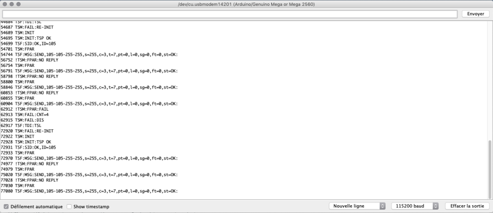
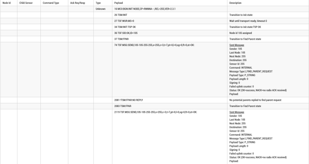
@hyperflemme you can check the log using the log parser
https://www.mysensors.org/build/parserHere it says it cannot connect to parent, is you gateway active, and on the same radio channel ?
-
@hyperflemme you can check the log using the log parser
https://www.mysensors.org/build/parserHere it says it cannot connect to parent, is you gateway active, and on the same radio channel ?
@nca78 what do you mean by log parser?
i just have put a gateway usb into arduino. -
@hyperflemme you can check the log using the log parser
https://www.mysensors.org/build/parserHere it says it cannot connect to parent, is you gateway active, and on the same radio channel ?
-
@hyperflemme as you can read "no potential parents replied to find parent request". It means no gateway replied to the radio calls.
Please describe your full mysensors installation if you want help :
- controller used ?
- board, radio used for gateway ?
- board, radio used for sensor ?
-
@kimot I have only 1 arduino, i have put the gateway into this card.
@hyperflemme
Than in your second sketch ( with sensors )
define MY_GATEWAY_SERIAL
is missing.
This sketch works like normal node without this, not as gateway with sensors connected. -
@hyperflemme as you can read "no potential parents replied to find parent request". It means no gateway replied to the radio calls.
Please describe your full mysensors installation if you want help :
- controller used ?
- board, radio used for gateway ?
- board, radio used for sensor ?
@nca78 Hi,
I just have an nrf24l01 plug into my arduino.
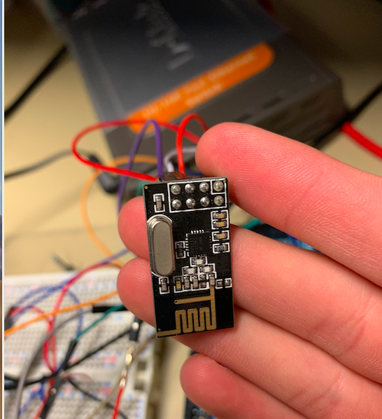
I miss something to make it work?
Thank's for helping me -
@hyperflemme
Than in your second sketch ( with sensors )
define MY_GATEWAY_SERIAL
is missing.
This sketch works like normal node without this, not as gateway with sensors connected.@kimot in my sketch for motion sensor you think i just have to had #define MY_GATEWAY_SERIAL on the top of the program?
Thank's for your help
-
@kimot in my sketch for motion sensor you think i just have to had #define MY_GATEWAY_SERIAL on the top of the program?
Thank's for your help
@hyperflemme said in Problem with sensors on arduino and domoticz:
@kimot in my sketch for motion sensor you think i just have to had #define MY_GATEWAY_SERIAL on the top of the program?
Thank's for your help
The arduino that is connected to computer with USB should have #define MY_GATEWAY_SERIAL yes, so it will behave as a gateway and send the data to the computer. You need to configure it in your controller (home automation software) also.
If you have 1 gateway (arduino + radio) connected to computer + 1 sensor (arduino + radio) separated then the sensor should not have this #define.
-
@hyperflemme said in Problem with sensors on arduino and domoticz:
@kimot in my sketch for motion sensor you think i just have to had #define MY_GATEWAY_SERIAL on the top of the program?
Thank's for your help
The arduino that is connected to computer with USB should have #define MY_GATEWAY_SERIAL yes, so it will behave as a gateway and send the data to the computer. You need to configure it in your controller (home automation software) also.
If you have 1 gateway (arduino + radio) connected to computer + 1 sensor (arduino + radio) separated then the sensor should not have this #define.
@nca78 all my sensor are connected on the arduino card with nRF24L01, and the arduino card is connected by usb on my computer. I want tu connect the arduino card at an raspberry pi 3 but she don't recognise arduino card and sensor, however i have put the gateway and sketch of sensor into the arduino card....
-
@nca78 all my sensor are connected on the arduino card with nRF24L01, and the arduino card is connected by usb on my computer. I want tu connect the arduino card at an raspberry pi 3 but she don't recognise arduino card and sensor, however i have put the gateway and sketch of sensor into the arduino card....
@hyperflemme what controller software are you using on the raspberry pi ?
-
@hyperflemme what controller software are you using on the raspberry pi ?
@nca78 Linux on raspberry pi 3 with domoticz
-
@nca78 Linux on raspberry pi 3 with domoticz
@hyperflemme did rebuild the gateway script with #define MY_GATEWAY_SERIAL ?
Then did you add the gateway in the hardware tab of domoticz ?
Hello! It looks like you're interested in this conversation, but you don't have an account yet.
Getting fed up of having to scroll through the same posts each visit? When you register for an account, you'll always come back to exactly where you were before, and choose to be notified of new replies (either via email, or push notification). You'll also be able to save bookmarks and upvote posts to show your appreciation to other community members.
With your input, this post could be even better 💗
Register Login