Skip to content
  • What's a good power bank for use with IoT?

    General Discussion
    20
    1 Votes
    20 Posts
    1k Views
    HJ_SKH
    @OldSurferDude Thanks a very valued to know. I was wondering today why my (big) powerbanks fall down after short time. I have small 1 & 2-pieces powerbanks, they work very well. I use also BSM hw-168 or hw-107 for charging single 18650. Will try to use them outside also with small solarpanels.
  • 0 Votes
    1 Posts
    130 Views
    No one has replied
  • 7 Votes
    226 Posts
    118k Views
    OldSurferDudeO
    What I didn't quite figure out was how it operates independently as a regular light switch. What I find most interesting is that this is 8 years old. There have been some incredible advances in the IoT world in that time. I was about to do a similar thing which morphed into an ESP-12F then added a touch screen. I call it the Universal Light Switch Imagine this: All the switches are identical. Any switch can easily be configured to control up to five devices ... and then changed, on-the-fly, to control a different set of devices. My design is part of a system that would require a controller (eg. Home Assistant), an MQTT broker, and receiving modules in the devices being switched. It's WiFI which assumes an access point. The DIY ULS is under $20 and the off-the-shelf receiving modules are under $10. (About the cost of a non-networked dimmer switch) If one doesn't have the controller and MQTT broker, they can run on an old (5 years?) computer (which is cheaper than an old RasberryPi). This project is a good one! OSD
  • Old hardware migration

    General Discussion
    3
    0 Votes
    3 Posts
    229 Views
    dbemowskD
    @OldSurferDude My old 2.0 setup is with nRF24L01 radios. This is a link to the thread on some light switches that I designed and built. https://forum.mysensors.org/topic/7376/us-decora-wall-switch-continued/2 I am aware that you cannot have two MQTT gatways. When I designed my old setup I was not that familiar with MQTT so I never ended up implementing it. On the home assistant server that I have set up though, I have installed the MQTT broker on there so I should be able to comunicate with any MySensors stuff over MQTT in the future devices I make/set up. As I mentioned, I do have a Home Assistant box that I have started about 4 months ago and eventually want to migrate my Vera equipment to the HA box. As for the YAML and Python, I'll muddle my way through. used to program in PHP and have done enough on Arduino that I'm sure it won't hurt my brain too much.
  • 0 Votes
    7 Posts
    3k Views
    dbemowskD
    @Michael-Link I have been out of touch with MySensors for some time now and looking to slowly get back into it. I created this and a few other boards back in 2018 All of the GERBER files for this are in the "Design Files" tab. Those you should be able to send to JLC PCB or one of the other fab houses and have some made. This was designed to be used with 2 other boards that I designed. There was the processor board and the power supply board. The processor board was designed in a way that I could use a couple different switch boards. This one and a universal multi-switch board that had multiple configurations. If you look here you will see my other boards.
  • openHAB 4 MySensors Binding

    OpenHAB
    19
    0 Votes
    19 Posts
    924 Views
    kerberosK
    Hi @adds666 I did in between the switch from 2.5.12 to 3.4.4 a change from pure textual configuration in 2.5.12 to a UI configuration in 3.4.4. This requires some homework. Can't remember beside the exchanged mysensors binding files anything else to upgrade to 4.0.4 from 3.4.4 and finally to current 4.1.1. Keep in mind, I use a OpenHAB manual installation on a non-Debian Linux system, not openHABian. This may have an influence, but I don't expect any hiccups. kerberos
  • 0 Votes
    2 Posts
    252 Views
    E
    @OldSurferDude well, the ESP8266 is limited to 4 TCP clients in arduino IDE. This can't be really increased. I did som experiments and you can set it up to 15, but after the 5th client on my web server, I got a freeze. Maybe you got something wrong. #define MY_GATEWAY_MAX_CLIENTS 2 defines how many controllers (eg Home Assistant) can connect to the gateway, not how many sensors/MySensors devices. And yes, you can have multiple TCP gateways in HomeAssistant. I got an NRF24, an RFM95 long range and a RFM95 short range gateway (all based on ESP32) on the same Home Assistant. Regards, Edi
  • Sleep mode for bmp280

    Hardware
    7
    4 Votes
    7 Posts
    4k Views
    __isded___
    Just wanted to say thanks for this, it is still relevant and useful six years later !
  • Serial Gateway woes

    Development
    1
    0 Votes
    1 Posts
    137 Views
    No one has replied
  • 0 Votes
    10 Posts
    552 Views
    E
    @wrendral said in "Remote Irrigation with LoRaWAN: LM27313 Challenges and PCB Design": I will go with a Li-Po Battery type: 304048 3.7V 1200mAh Might work, but maybe the internal protection will trigger with the high current peaks. I'd suggest you plan a 0 Ohm, (2512/THT) resistor as R2 and then replace it with a 100Ohm/1Watt if the protection triggers.
  • 0 Votes
    3 Posts
    208 Views
    A
    Hi OSD, thanks for your input. 
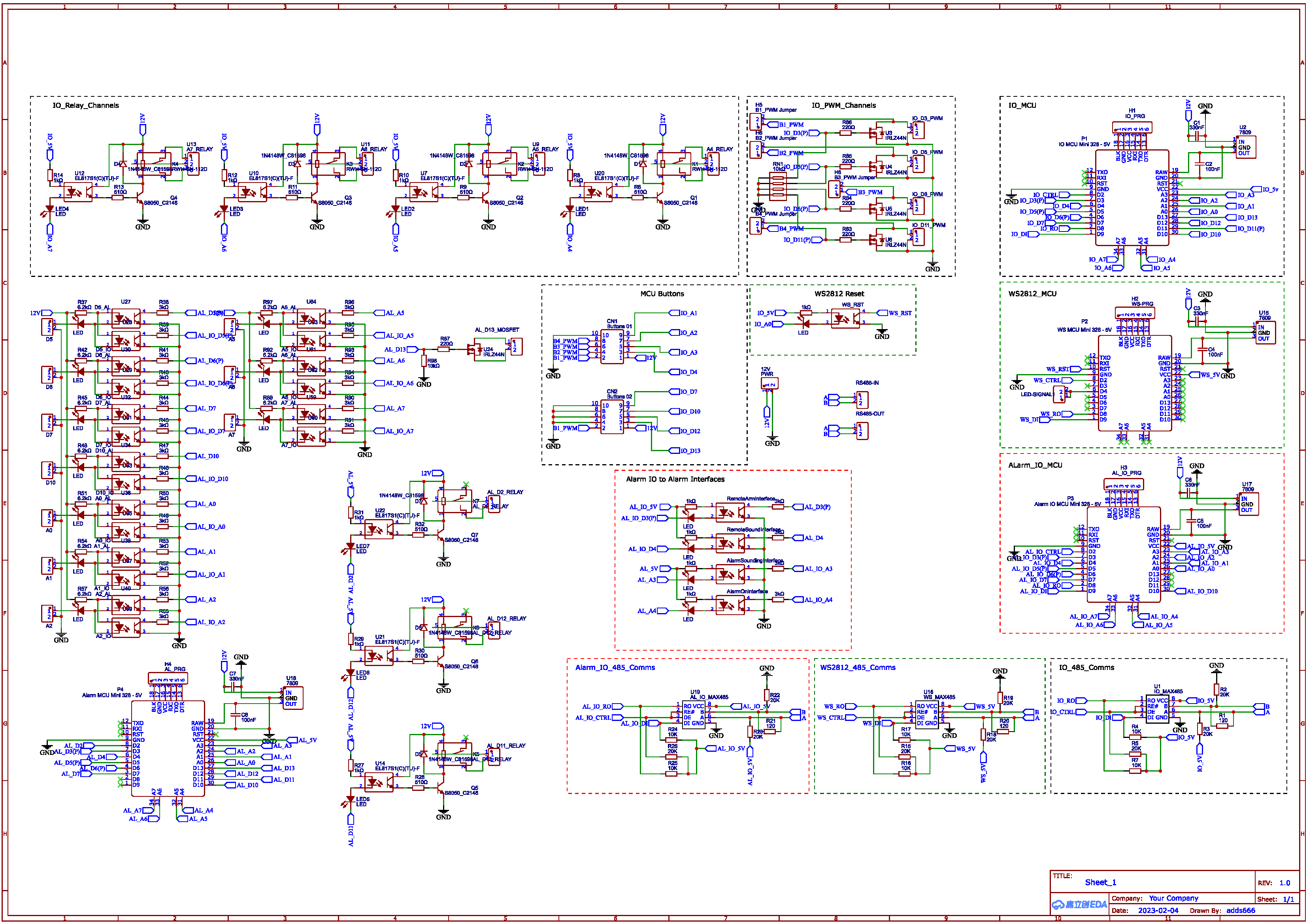
Those are the 4 relays on IO-MCU. I buzzed out the circuit and found that I had an open circuit on the 12v line to the relays. Furthermore 2 of the relays indicator LEDs were illuminating, 2 were not. I suspect, when I first juiced up the circuit on this MCU, the 2 relays fired, but I'd made the trace too thin for the required current. I wired up some jumper wire on the reverse of the PCB and the 2 relays started working. The 2 that remain inoperable? https://forum.arduino.cc/t/using-pins-a6-a7-on-pro-mini-compatible/118050 A6 and A7 can only be analogue inputs, cannot be digitally written to..... - so this part of my PCB is now redundant. However, all in all, some good fault finding, found the two issues, and I'm now going away to re-think my PCB trace widths and reading the datasheets more accurately ;) Thanks
  • Gateway on Raspberry pi 1

    General Discussion
    9
    0 Votes
    9 Posts
    421 Views
    E
    @mimaret It was a pleasure. Thank you for your feedback!
  • 0 Votes
    1 Posts
    107 Views
    No one has replied
  • Most reliable "best" radio

    General Discussion
    274
    1 Votes
    274 Posts
    18k Views
    L
    It has been a long time but I’ve learned a few things that I wanted to share. This library of information (Thank you NeverDie and others) has been so helpful in my hobby developments. Software Defined Radios for signal analysis. With the help of Andreas Spiess explanation of IQ transformations, I learned about Software Defined Radios and I bought one (RTL-SDR). Using this I can clearly discriminate between effective 433 MHz transmitters and bad ones. Not only is the signal density displayed on the software (SDR#) but so is the frequency. Power Profiler Kit II has been indispensable in watching power usage and seeing into the details of the radio transmission. In effect this thing has saved me from buying an oscilloscope for my simple little bench. Tonight, I saw this video: https://www.youtube.com/watch?v=Z9nycymUd-I It describes common PCB errors. It is too advanced for me, but I did pick-up a few ideas about ground planes (tip #6 from the video). I hope this is of some value for folks.
  • Home Assistant update changed USB port name

    Home Assistant
    3
    0 Votes
    3 Posts
    252 Views
    E
    What I did not try but might work: copy your persistence file, delete the old GW and create a new one with the persistence file you copied. Maybe the devices are preserved like this. Maybe you should create a full backup before... <edit: typo>
  • 0 Votes
    2 Posts
    209 Views
    OldSurferDudeO
    I have success! (oops, that's suppose to be Timer1) I only sample for 1/60 of a second. What I did was to back up all the timer registered I used and then resorted them after I was done sampling. (As opposed to initializing the registers in setup and then starting the timer when needed.) Now I have a Nano sampling the data and sending it to a MySensors Gateway on an RPi3B+ which then sends it to an MQTT broker runing on an old laptop. Also running on the laptop is Home Assistant running inside of VirtualBox. If MySensors does use Timer1, it appears that restoring the registers allows it to be shared. //------------------------------------------------------ISR ISR(TIMER1_OVF_vect){ // interrupt service routine for overflow TCNT1 = TimerPreloadValue; // must be first line! starts the timer counting again digitalWrite(TRIGGER_START_SAMPLE_PIN,HIGH); samplesVolts[--sample]=analogRead(VOLTS_IN_PIN); // decrement before capturing samplesCurrent[sample]=analogRead(CURRENT_IN_PIN); digitalWrite(TRIGGER_START_SAMPLE_PIN,LOW); if (!sample){ // count down to zero digitalWrite(TRIGGER_START_SAMPLE_PERIOD_PIN,LOW); // indicate that sampling is complete samplingEnd = micros(); TCCR1B &= 248; // turns off timer } } //------------------------------------------------------sampleOneCycle void sampleOneCycle(){ // back up timer registers uint8_t TCNT1_b = TCNT1; uint8_t TCCR1B_b = TCCR1B; uint8_t TCCR1A_b = TCCR1A; uint8_t TIMSK1_b = TIMSK1; // configure timer which starts the sampling noInterrupts(); // disable all interrupts TCCR1A = 0; TCCR1B = 0; TCNT1 = TimerPreloadValue; // preload timer //TCCR1B |= (1 << CS10)|(1 << CS12); // 1024 prescaler TCCR1B &= 248; // turns off timer? TIMSK1 |= (1 << TOIE1); // enable timer overflow interrupt ISR // demark sampling sample = NUMBER_OF_SAMPLES; // count down to zero digitalWrite(TRIGGER_START_SAMPLE_PERIOD_PIN,HIGH); samplingStart = micros(); TCNT1 = 65535; // first trigger right away! TCCR1B |= 1; // turns on timer interrupts(); // enable all interrupts // wait for sampling to be complete while(digitalRead(TRIGGER_START_SAMPLE_PERIOD_PIN)){}; samplingEnd = micros(); // restore timer registers TCNT1 = TCNT1_b; TCCR1B = TCCR1B_b; TCCR1A = TCCR1A_b; TIMSK1 = TIMSK1_b; }
  • 0 Votes
    1 Posts
    132 Views
    No one has replied
  • Raspberry pi gateway problem after change of Pi

    General Discussion
    2
    0 Votes
    2 Posts
    203 Views
    Vasilis VlachoudisV
    After re-installing the previous 32bit raspbian version, the gateway seems to work ok. It seems to me there is a problem with the 64bit version.
  • 2 Votes
    1 Posts
    143 Views
    No one has replied
  • Sensebender Gateway (SAMD21)

    Development
    10
    0 Votes
    10 Posts
    377 Views
    P
    Just for completeness: the right way to do this is to add the json under ~/.platformio/boards and the other files as described in https://community.platformio.org/t/how-use-a-same-chip-but-with-different-environment/18082/4

13

Online

11.8k

Users

11.2k

Topics

113.2k

Posts